OP
OP
WD Pro
Well-Known Member
- Joined
- Jan 18, 2018
- Threads
- 132
- Messages
- 6,798
- Reaction score
- 13,640
- Location
- United Kingdom
- Vehicle(s)
- Lime GT
- Vehicle Showcase
- 1
- Thread starter
- #406
Thinners :

Iron remover :

More thinners needed :
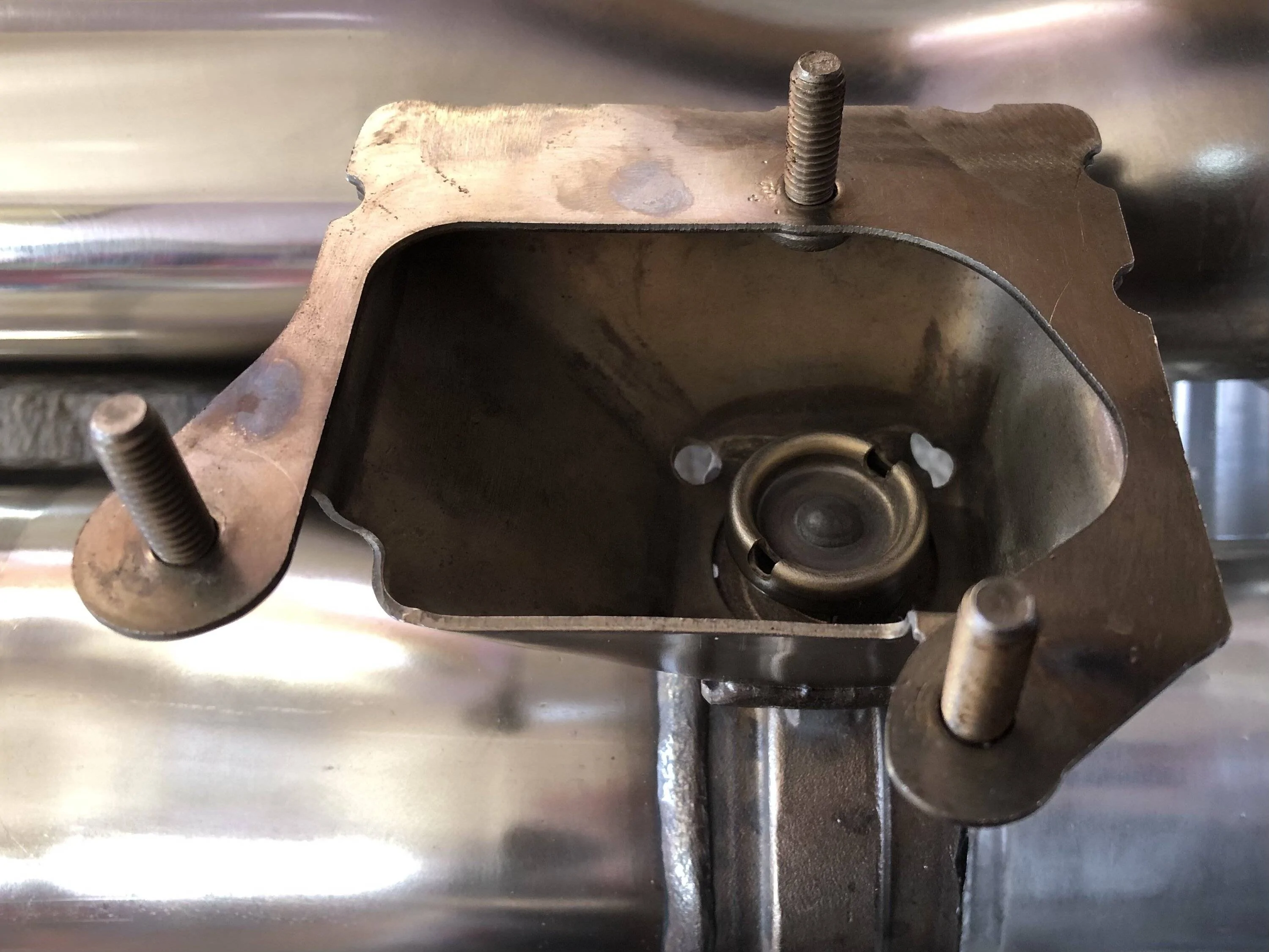
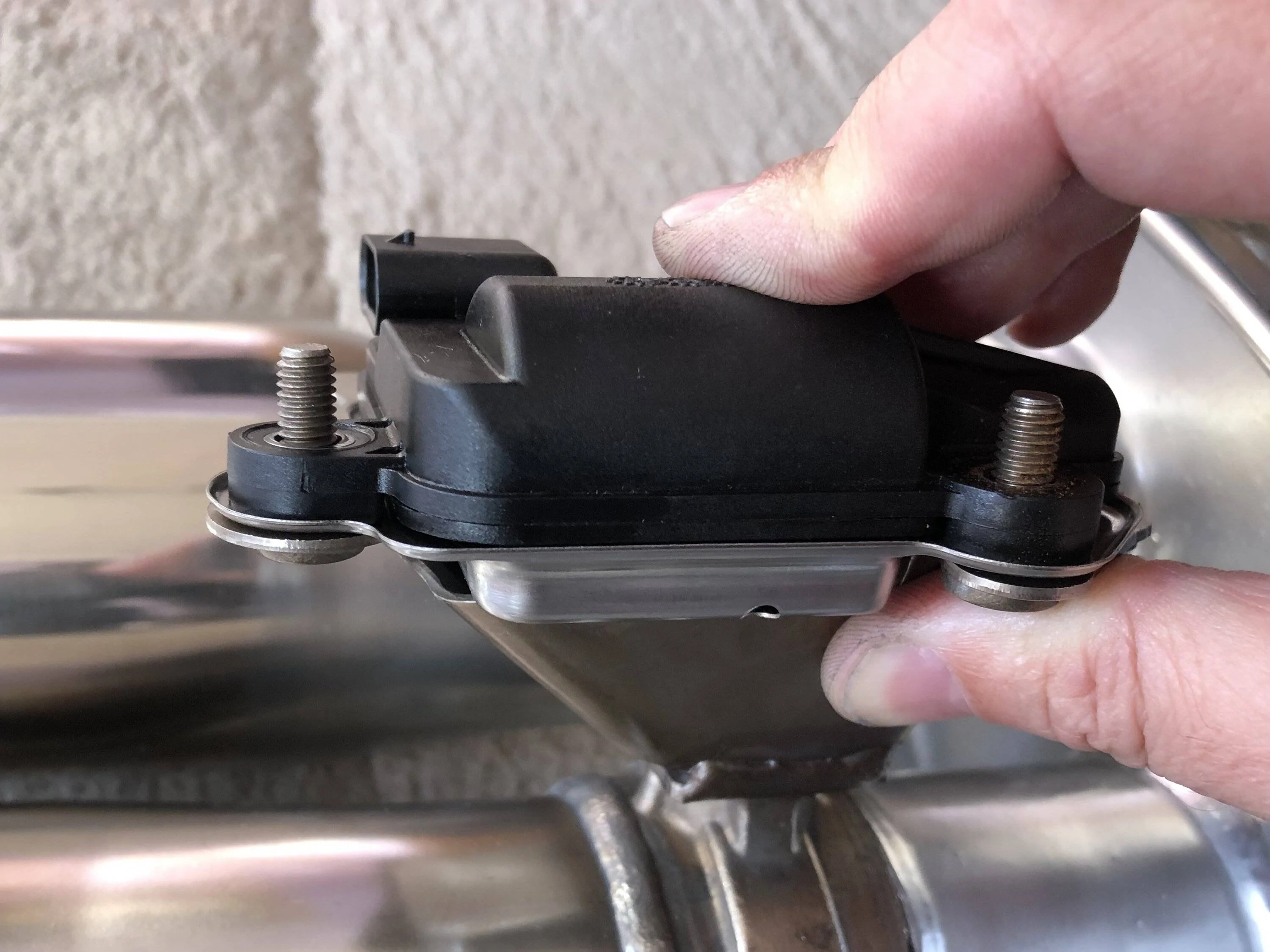
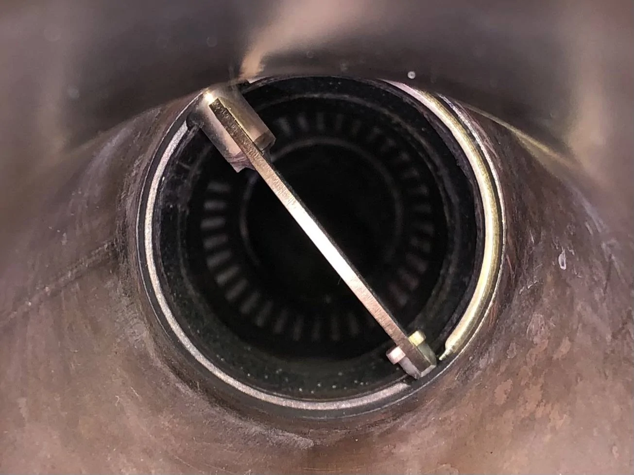
The known active exhaust issue, this had loads of clearance when cold, but obviously not quite enough when hot (hence shortening the h pipe and exhaust) :
No structural damage though so all is good.
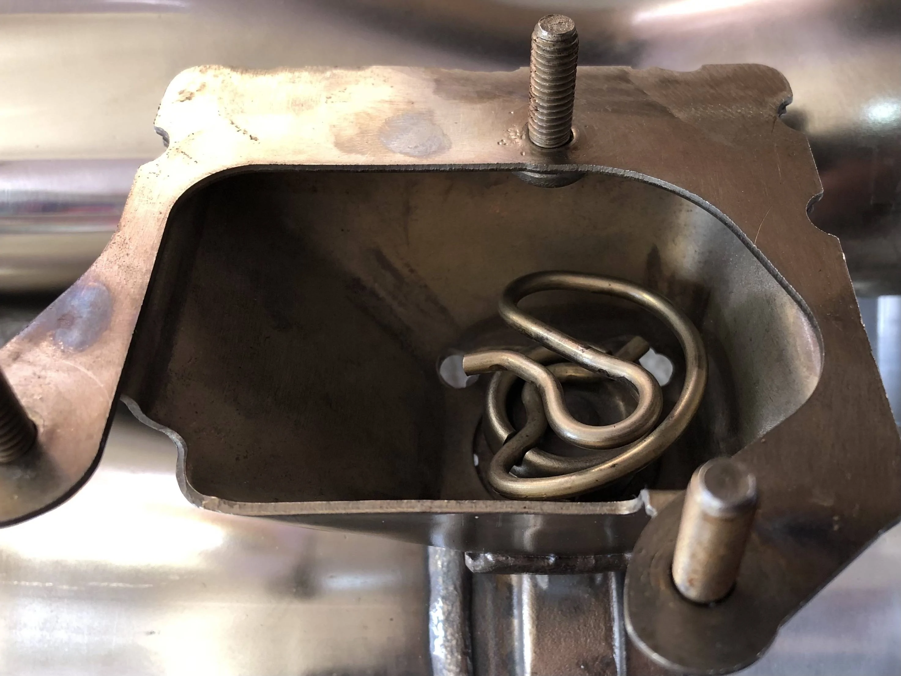
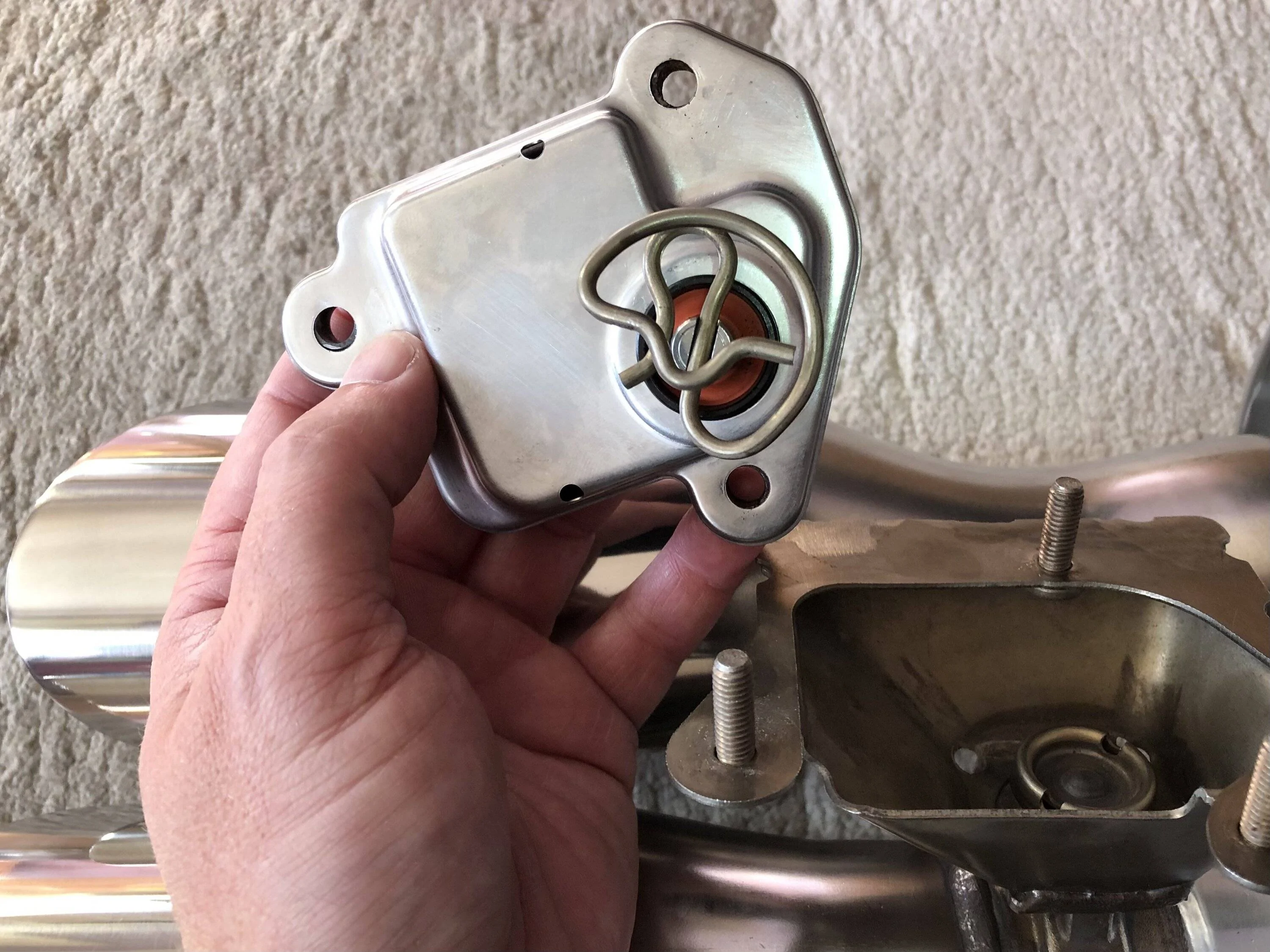
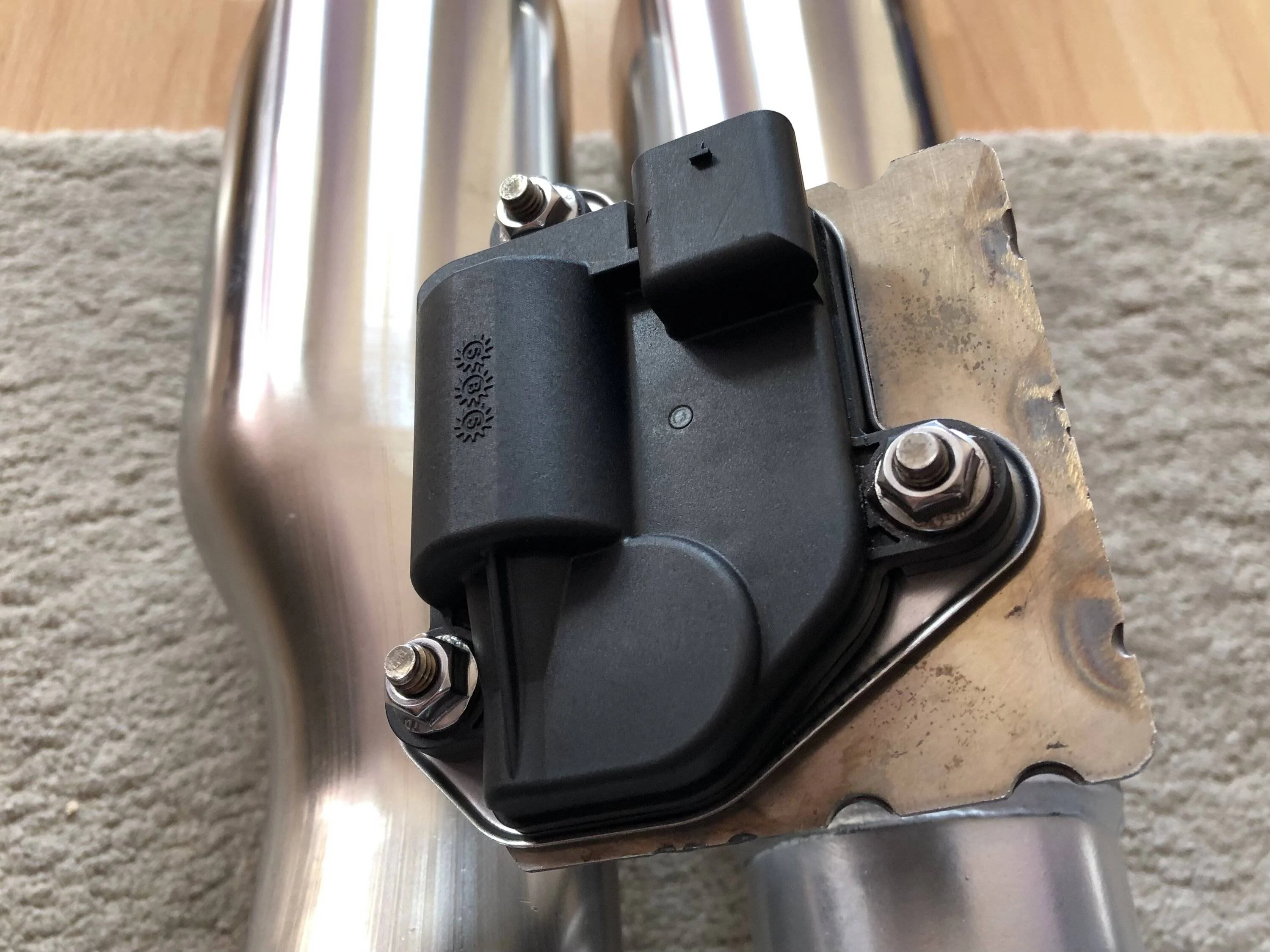
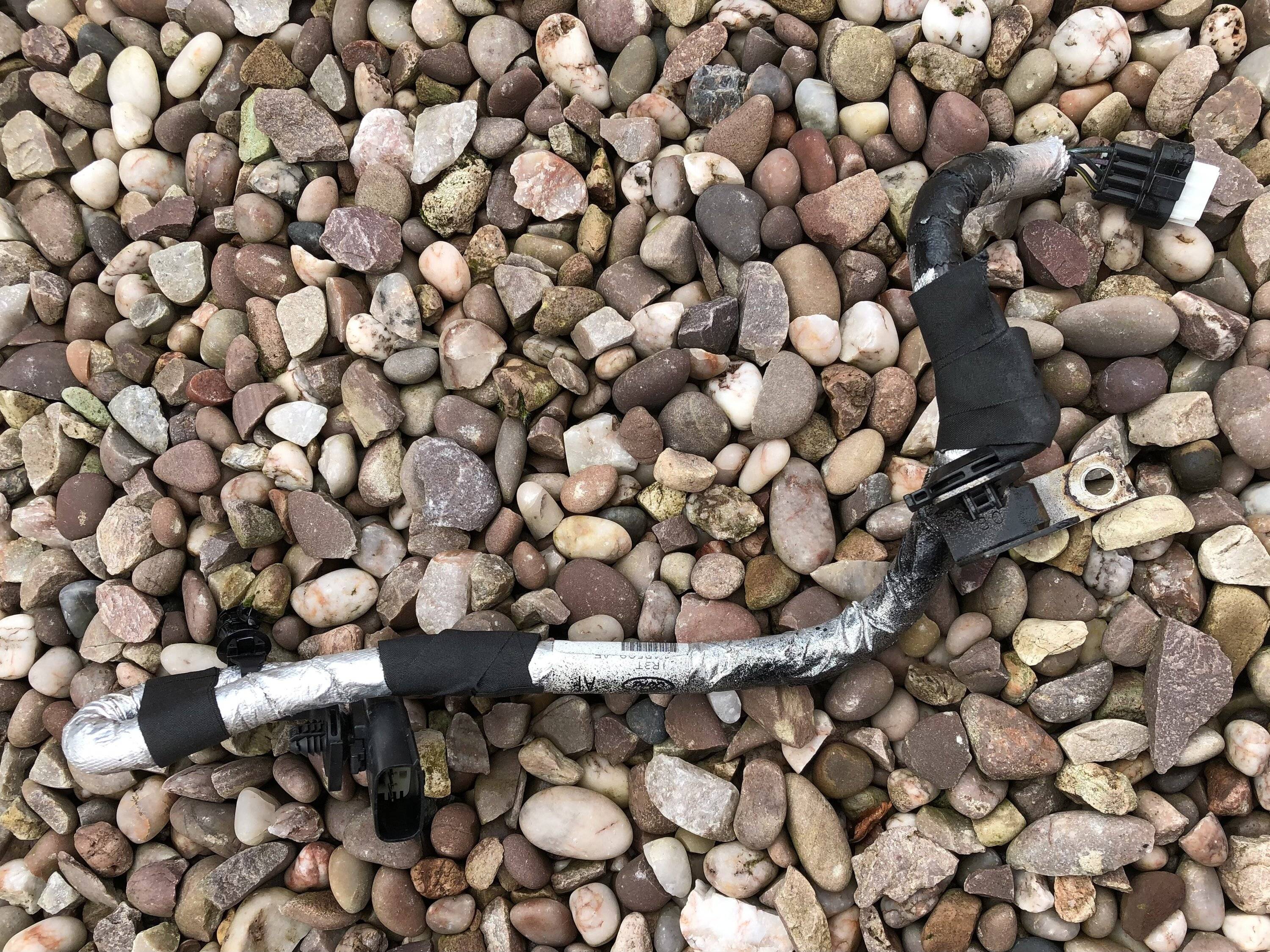
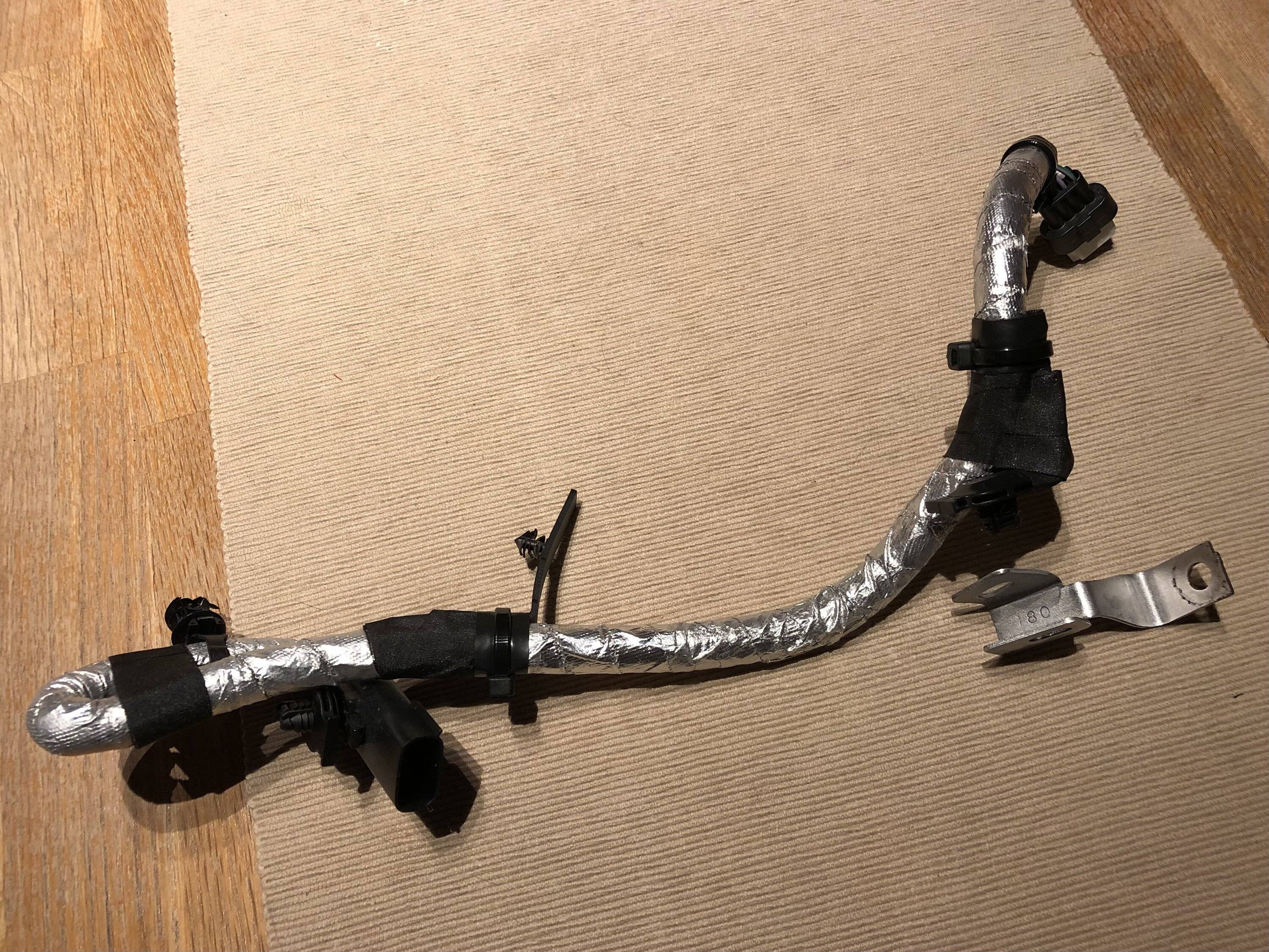
After a bit of tidying up :

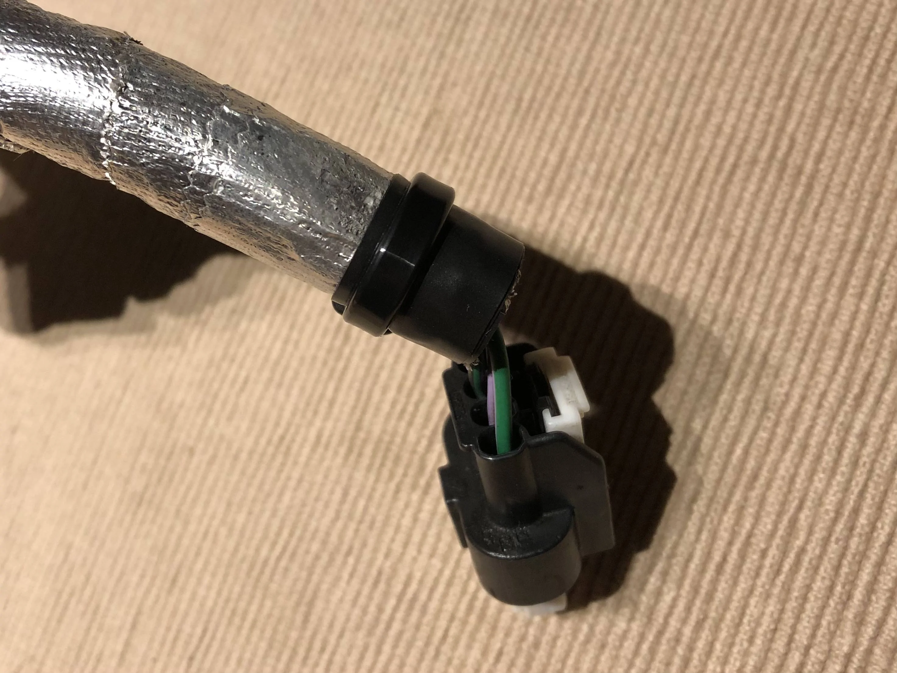
I don’t think it will touch the frame again, but if it does it’s now got a cable tie and layer of tape to help protect it.
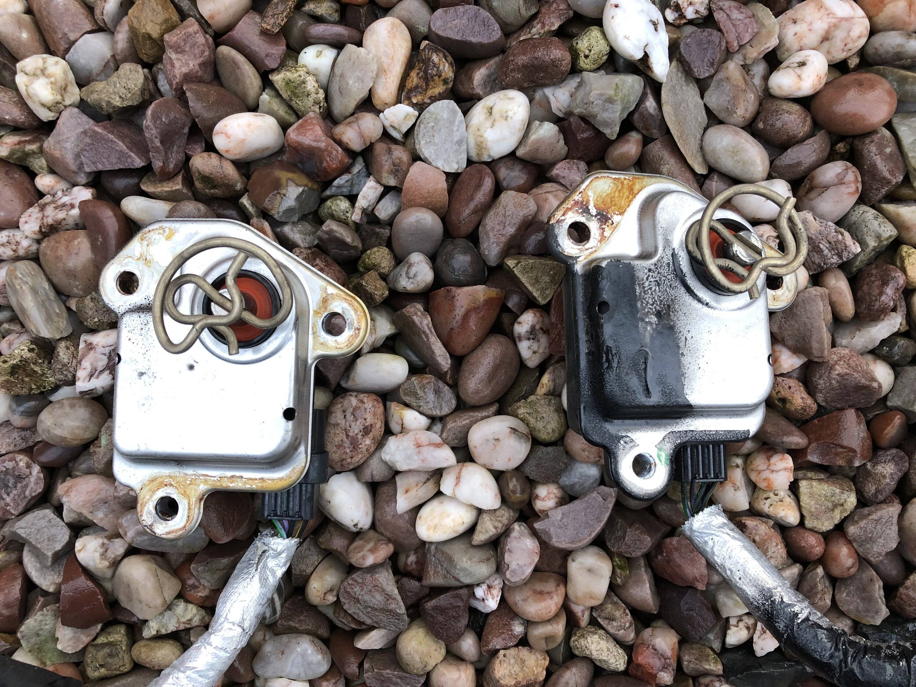
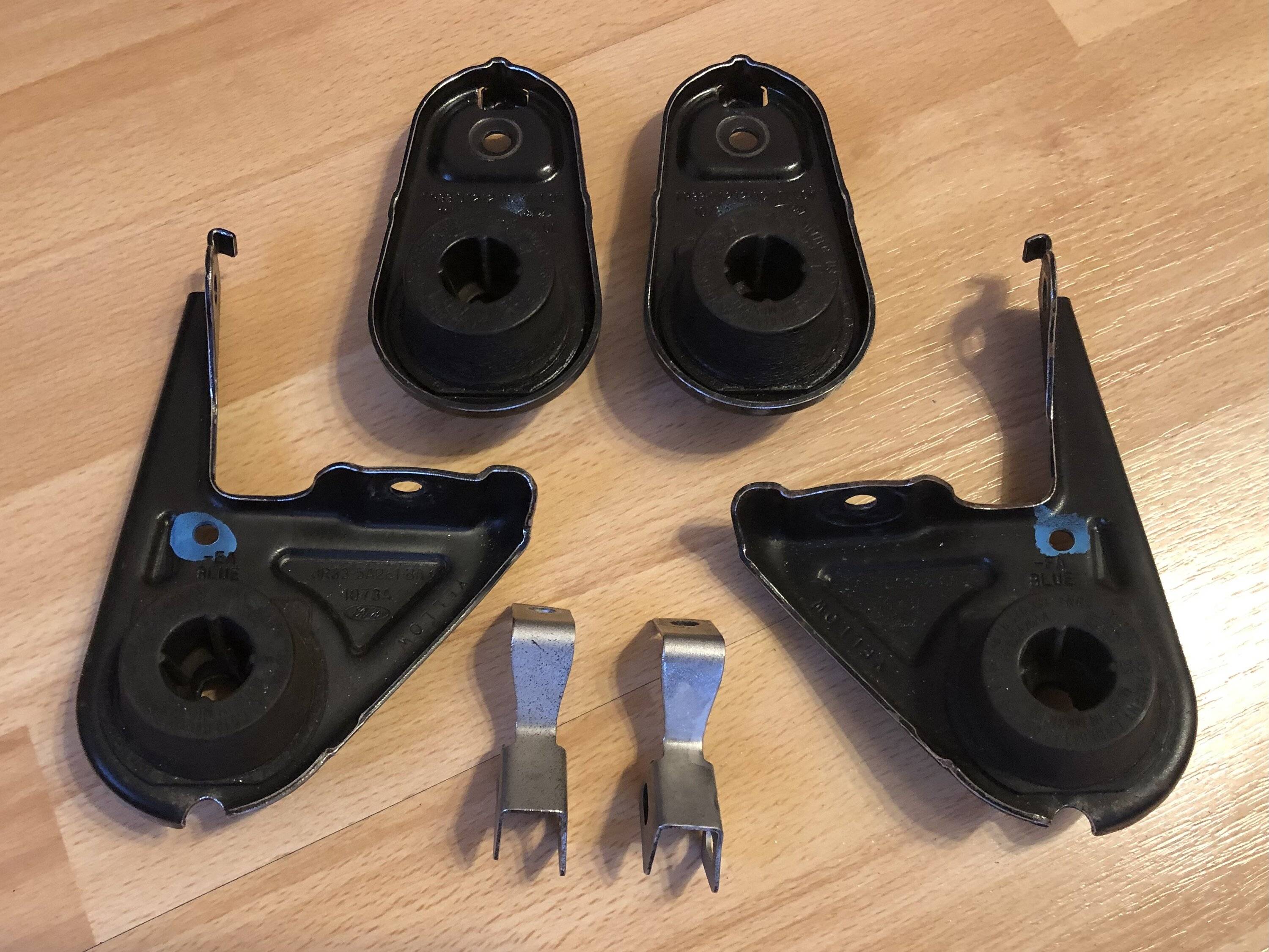
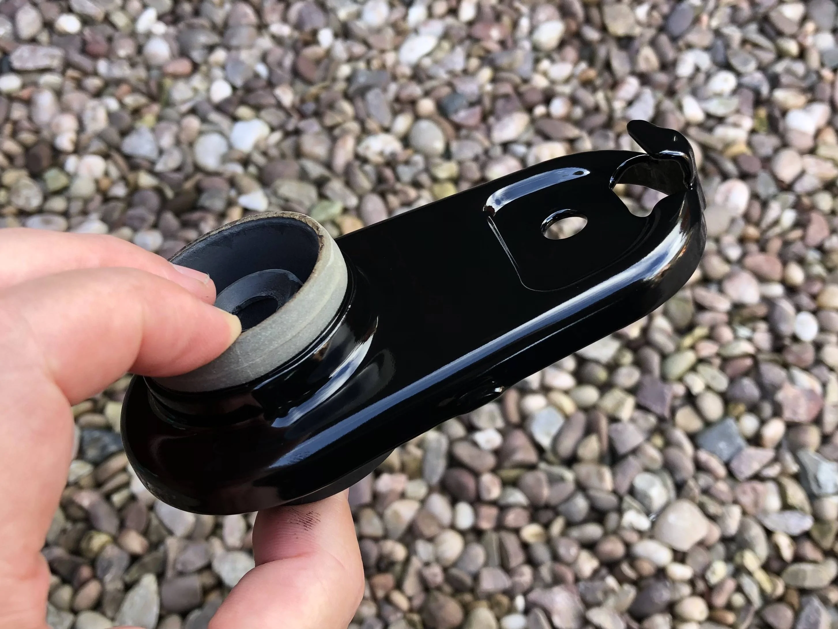
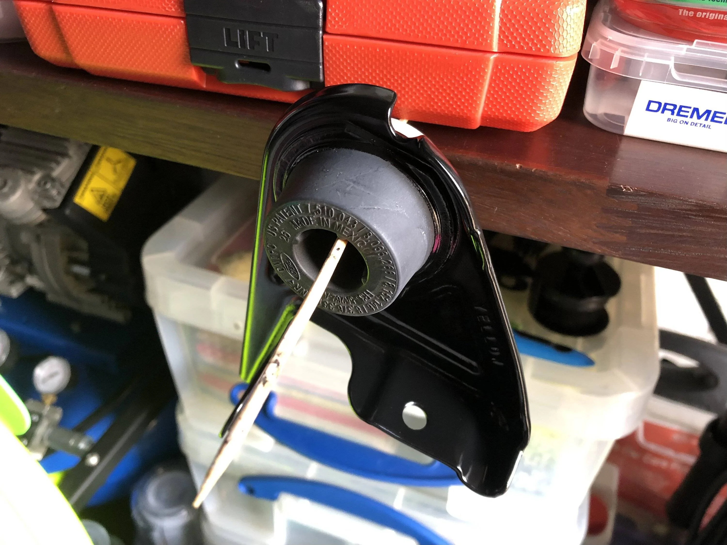
Exhaust bracket, the flash makes it look worse :
Blunted all the sharp edges with the die grinder :
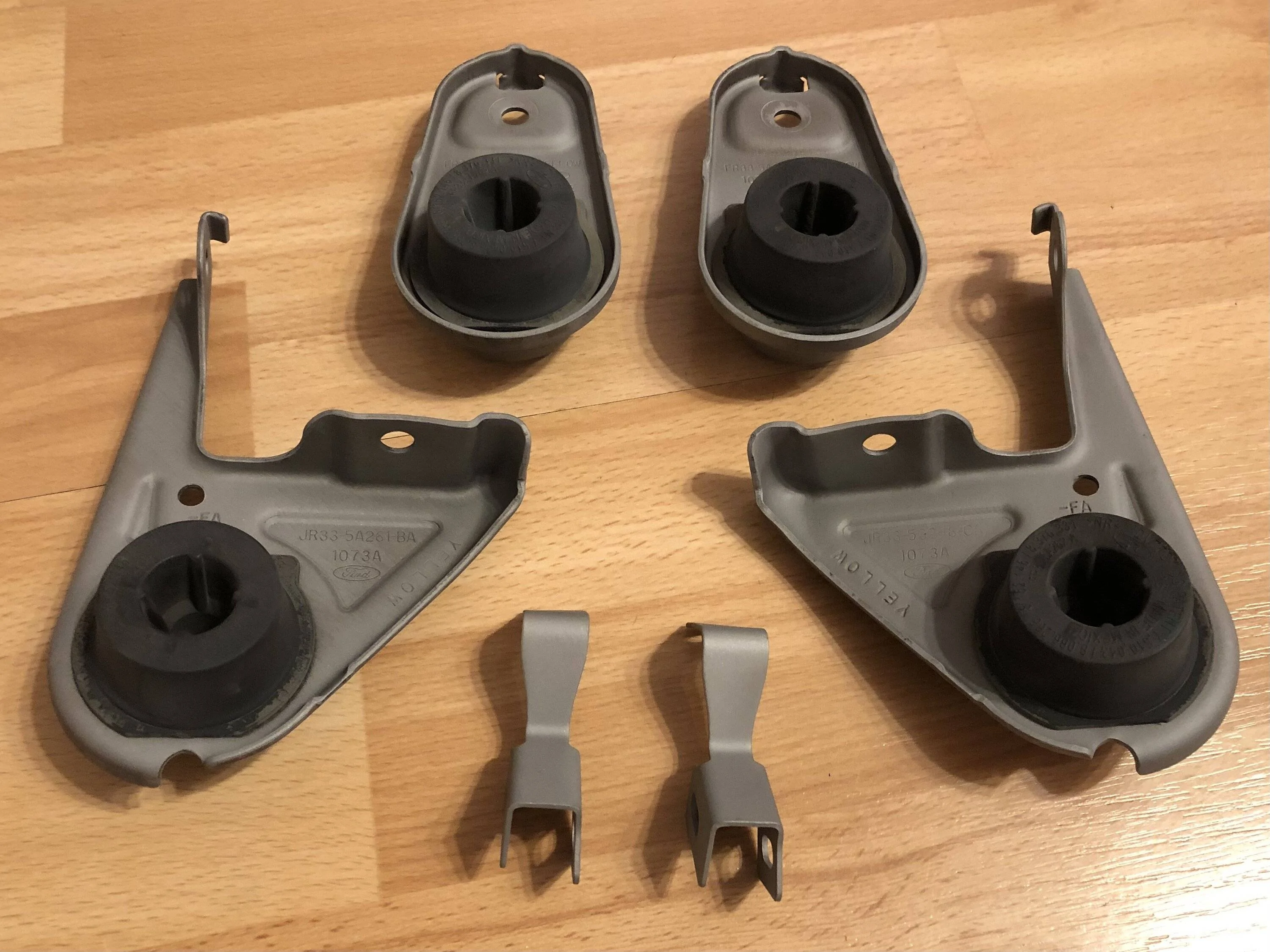
Blasted :
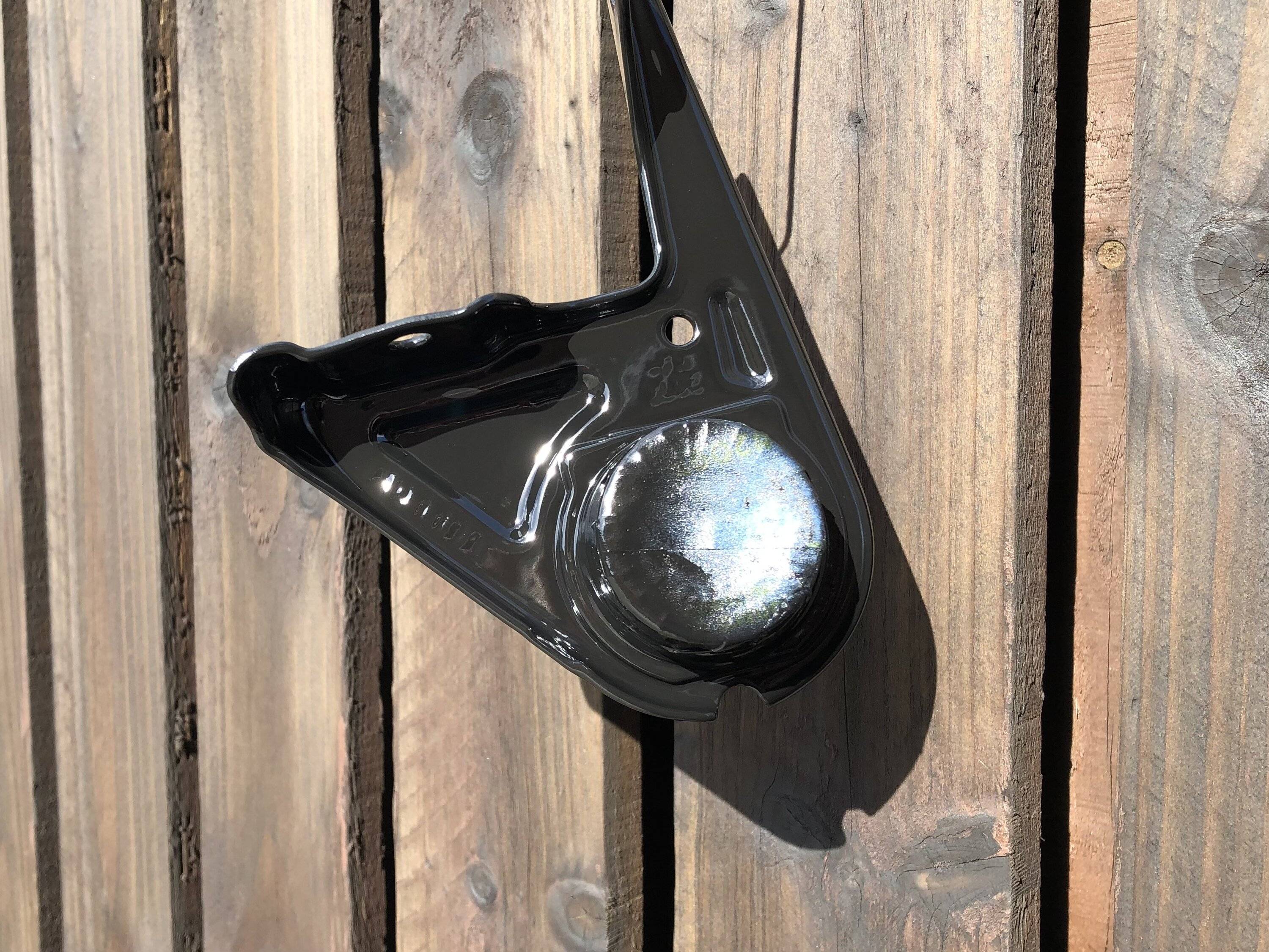
I just need a dry evening now so I can mask and paint
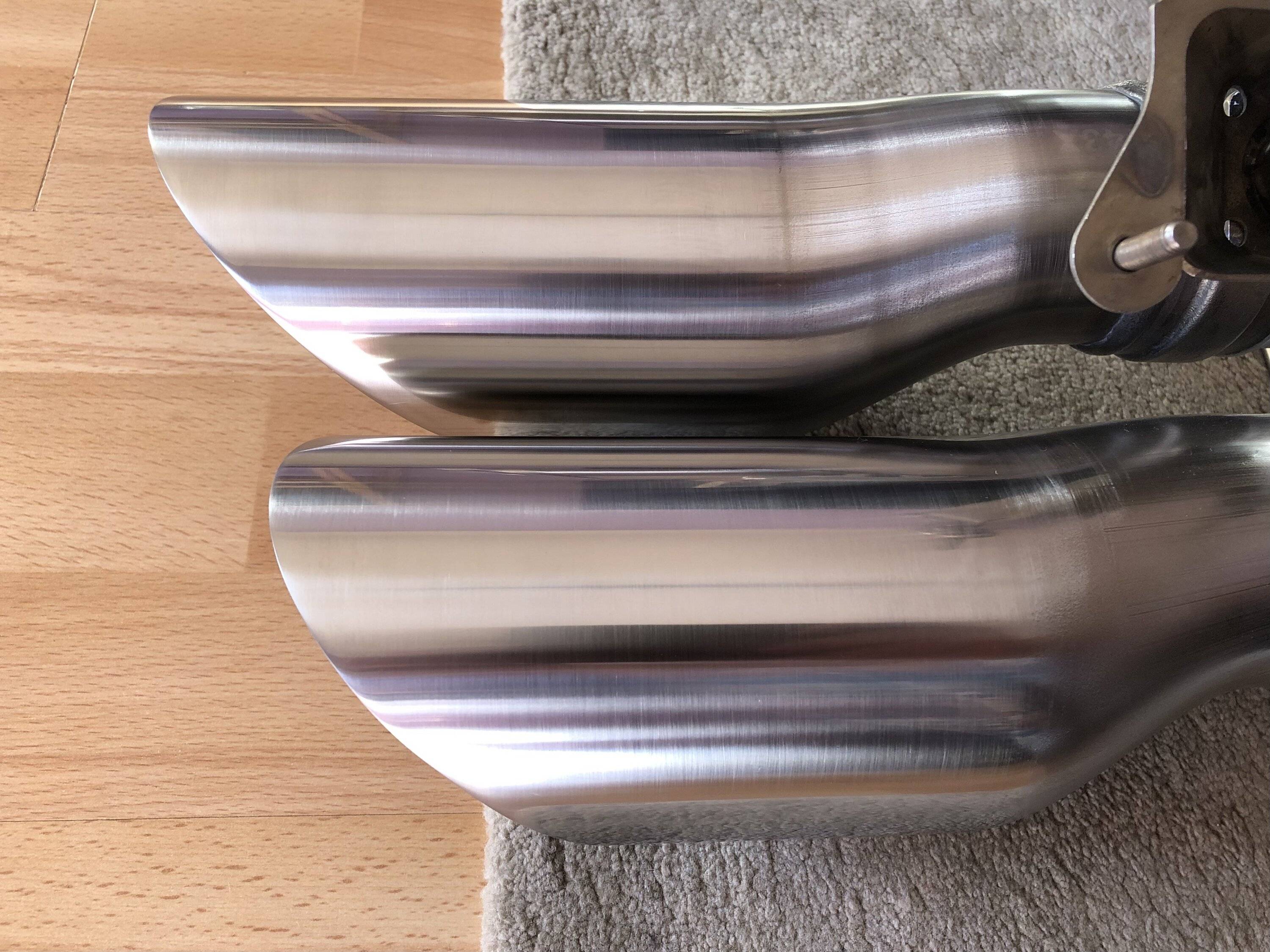
My exhaust is now coated and it should be getting burnished and polished tomorrow. It’s being done Tech Line CermaKrome which is a metallic ceramic coating
WD

Iron remover :

More thinners needed :
The known active exhaust issue, this had loads of clearance when cold, but obviously not quite enough when hot (hence shortening the h pipe and exhaust) :

No structural damage though so all is good.
After a bit of tidying up :
I don’t think it will touch the frame again, but if it does it’s now got a cable tie and layer of tape to help protect it.
Exhaust bracket, the flash makes it look worse :
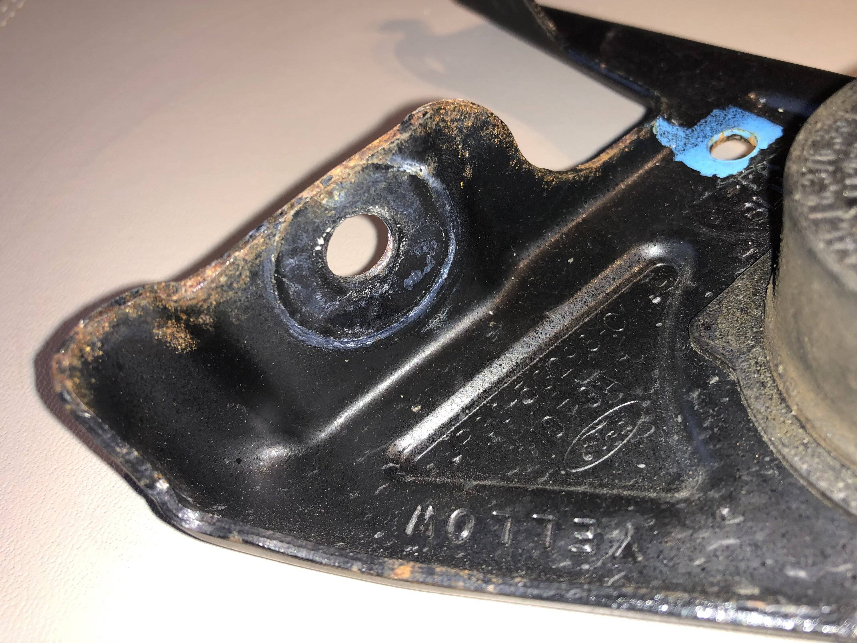
Blunted all the sharp edges with the die grinder :
Blasted :
I just need a dry evening now so I can mask and paint
My exhaust is now coated and it should be getting burnished and polished tomorrow. It’s being done Tech Line CermaKrome which is a metallic ceramic coating
WD
Sponsored
 )
)


 ) I will give them a low temp bake in the oven …