engineermike
Well-Known Member
- Thread starter
- #1
. . . and I didn't blow the engine. I set out to figure out exactly how the injector duty cycle air limit works, confirm it works, and make it work better. What I learned was that it works shockingly well. . . but "we" sabotage it and prevent it from working in various ways.
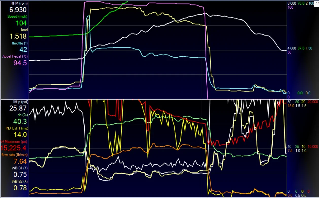
The final result is graphed below. This is a Whipple 2018 on the 3.0" pulley, GT500 55# injectors, and a single stock pump without even a BAP. You can see the throttle instantly opens, following the driver request, but very quickly responds by closing. It then modulates throttle, and lambda stays right at commanded even though fuel pressure drops to only 26 psi.

After a ridiculous amount of testing and logging, I figured out a lot about how the logic works. This is where PCMTec excels, because you can log countless "intermediate steps" and calculation outputs to help figure this stuff out. What it's doing is calculating the potential GDI and PFI injector flow at current pressures, temperatures, and rpm, adds them together and multiplies by desired A/F ratio to obtain a max airflow it can support. If this limit falls below the current airflow, it will modulate throttle until they match. In PCMTec, you can log the injector duty cycle airflow limit and see how it tracks against actual airflow. Below you can see the airflow limited by injector duty cycle in green. When the red (actual MAF) meets the green (injector-limited air flow), it modulates the throttle to ensure it doesn't flow more air than the injectors can support.

So, why do we hear about these coyotes going lean and popping pistons? That's because "we" sabotage the system and prevent it from doing its job.
Sabotage 1: This one is actually from Ford and I accidentally found it. As I said, it calculates port injector flow potential as a function of rpm, temp, and current dP. The dP is rail pressure minus calculated (MAF) or measured (SD) manifold pressure. The problem is that basically all PFI high slope pressure multiplier tables (auF30941) are only scaled down to 25 or 30 or 40 psi or even 55 psi, but never 0. So if the injector dP drops below the bottom of the scale, it can only assume the bottom multiplier holds true. In the case of a stock Mustang GT, the lowest high slope multiplier is .875 so even if the fuel pressure drops to zero it still thinks its getting 87.5% of the rated injector flow when it's really getting 0. This can be fixed by scaling the table auF30941 down to 0 psi, where the multiplier is also 0.
Sabotage 2: The GDI injector duty cycle safety factor (auF34946) has a misleading name in both HPT and PCMTec. It sounds like it's a limiter for the GDI injector duty cycle but it actually doesn't function this way at all. You can change this to 20% and you'll still get the same GDI injection as before. In reality, this factor is multiplied by the GDI injection potential flow when calculating the airflow limit. In aftermarket tunes I've seen this set to 1.05 to 1.25 or even higher. Doing this lies to the logic by telling it that the GDI injection can flow more than it can, thus preventing throttle from closing until after it's run out of injector. Stock is generally set to .95 but I raised mine to 1.0 to eek out a little more.
Sabotage 3: The TB model. . . and this was the toughest one to overcome. The issue here is that most aftermarket TB models are well calibrated in the normal usage range (<45 deg) because they use WOT start and end to force it to WOT beyond that. Good control at high angles is not usually necessary. However, to accurately control airflow at high flow rates requires an accurate TB model even up past 60 deg. Also, for example, the stock Whipple oval TB is factory calibrated out to 12 sq in flow area, which seemed reasonable and is much bigger than stock. However, in order to control load in the 1.5+ range, it needs to be accurately calibrated out to 30 sq in (!!!) range. This can be done by logging flow area request to see how high the scale needs to go, then calibrating the model out to that flow by tweaking the model until actual MAF matches desired air flow.
Furthermore...there is some sort of logic that slows down the response of the calculation. Setting auF34830 and 34831 to very low numbers speed up the response time of the air flow limit calculation.
I've tested this extensively after the above changes and it works extremely well, and it never allowed it to go lean. I'm truly impressed by the OEM logic on this.
Bonus: The P008a code comes in when lift pressure doesn't match demanded, but the stock setting is such that it has to fall below demand by 20 psi for 5 seconds. I've changed these to 5 psi for 1 second so I can get the early warning of a problem sooner. These are auF 36014 and 37359.
I hope you guys find this useful and it prevents a popped engine or two.
For clarification, the only time it hits around 18 psi is in the midrange when the fuel flow demand isn’t that high. Up top it’s cutting it back to 10-12 psi.
Sponsored
Last edited: