Sponsored

Rebuilding IRS

DougS550

Well-Known Member
Joined
May 18, 2020
Threads
317
Messages
4,735
Reaction score
2,703
Location
Fishers, Indiana
First Name
Doug
Vehicle(s)
2019 GT Premium A10 PP1 Whipple Stage 2
I feel the same way. After I got the DS bolts out, and had the whole assembly sitting on the jackstands, I said to myself, "this is the way to do it".
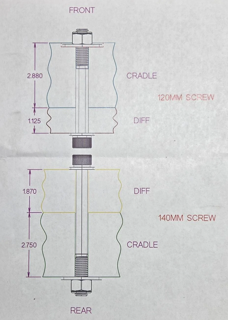
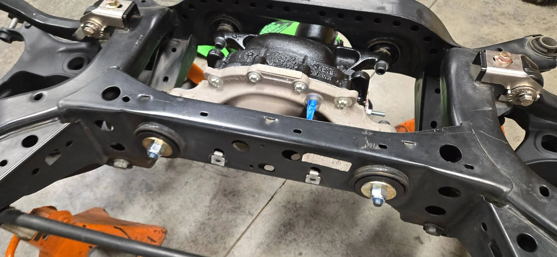
Definitely makes upgrading the diff bushings easier replace.
Sponsored


GTP

Deutsche Pony
Joined
May 27, 2015
Threads
261
Messages
5,977
Reaction score
3,859
Location
Indy
Website
www.BambergAudio.com
First Name
Philip
Vehicle(s)
2019 GT PP1 A10 Outrageous Orange HPDE mods
I just did, and it was super clear and helpful. Actually, just added that ABN wrench and some wobble extensions to my amazon cart, to make our lives easier when alignment time comes.
Thanks man!
I went through a lot of trouble to install and then use those inboard cam adjusters. But if you follow my write-up as a guide, I think things will go much better for you.

I think if you like to save money (like me) and therefore want to stick with the OEM arms, then you are relegated to land on a single fixed rear camber angle. The adjuster helps you achieve that with more control. I only change front camber and toe between daily and track settings, but use a compromise alignment in the rear.
 
OP
OP
eisenhauer01

eisenhauer01

Well-Known Member
Joined
Apr 1, 2019
Threads
22
Messages
226
Reaction score
255
Location
Walkertown, NC
First Name
Kenny
Vehicle(s)
2015 Mustang GT
I think if you like to save money (like me) and therefore want to stick with the OEM arms, then you are relegated to land on a single fixed rear camber angle. The adjuster helps you achieve that with more control.
That is exactly what I was looking for. I am not into track or anything, it is my fun car.
I wanted to be able to align it precisely to my spec without dealing with the slotted hole prybar ordeal. It will be an easy install with the subframe out, and your write up (along with the tools you suggested) will make that as easy as possible. I understand the camber arms for guys that are constantly adjusting for their purposes, but that's not me. I appreciate your write up.
 

GTP

Deutsche Pony
Joined
May 27, 2015
Threads
261
Messages
5,977
Reaction score
3,859
Location
Indy
Website
www.BambergAudio.com
First Name
Philip
Vehicle(s)
2019 GT PP1 A10 Outrageous Orange HPDE mods
Yes, it will be quite easy to put those brackets in place, and you can even use a torque wrench on them!

Also, check the DIY section under GTP for tips on affordable DIY camber and toe measurement.
 

Sponsored

OP
OP
eisenhauer01

eisenhauer01

Well-Known Member
Joined
Apr 1, 2019
Threads
22
Messages
226
Reaction score
255
Location
Walkertown, NC
First Name
Kenny
Vehicle(s)
2015 Mustang GT
Made some progress..
Installed the Steeda RLCA spherical bearings. Took every bit of my 20 ton press to get the old ones out. The new ones went in nicely and their aluminum piece for installation was a nice add I thought. Wish I would have gotten a few pics.
Anyways, cleaned up the rear subframe a little bit, and installed the Steeda Rear Camber Adjustment Kit. It went ok. They are nice pieces, only one complaint. When they put machined the two flats onto the cam bolt, they didn't go back and run a die over the threads. The one side of the threads were full of burrs from the machining process. This proved to immediately cause gaulding of the threads on the nut. Luckily I had a M12 die, so I re-chased them and all was good. I stole GTP's idea for adjustment of the camber during alignment with the swivel extensions, which I think is pretty cool.

1000004959.jpg


The rear control arms had a ton of black overspray on them from a previous owner spray bombing the exhaust for selling purposes (I imagine) so I went ahead and dusted them both flat black.
Installed them, and torqued the four 24mm bolts down.

1000004961.jpg


I had been thinking about it, and staring at that rusty diff got the best of me. With a bunch of brand new parts going into this thing, I couldn't leave it ugly. Cleaned it up, and got a small can of POR15 and gave it a coat.

1000004960.jpg


Also, my tube of 3M Urethane came, so I shot up the diff bushings.

The FP GT350 Half Shafts showed up today, so they will be ready to go in when I'm ready!

1000004962.jpg


Still waiting on a bunch of parts to come, so might as well make the most out of the down time over the winter.
More to come later.
 
OP
OP
eisenhauer01

eisenhauer01

Well-Known Member
Joined
Apr 1, 2019
Threads
22
Messages
226
Reaction score
255
Location
Walkertown, NC
First Name
Kenny
Vehicle(s)
2015 Mustang GT
Some progress.
Originally, I was planning to use the Steeda Through Bolt Kit. This would not require drilling anything out, and would be the easiest solution.
After some thought, I didn't really want to have any threaded portion of the hardware at the point of possible shear (differential mount to subframe mount).
So I looked at the Lethal Extreme option, but I wanted it to be truly through bolted, and their kit only through-bolts the front. The rear still utilizes the threads in the aluminum diff cover.
I am sure it is 100% fine, just my not my preference.
That left kelltrac's big bertha. Pondered it, but decided to make my own path.
Took some measurements, and began piecing it together.

20250106_175217.webp


-Full 14mm shank at the shear point between the cradle and the diff.
-Minimal protrusion on the front side of the cradle (to eliminate the possibility of interference with the fuel tank).
-All bolts go in from the Differential side, so theoretically, if the diff ever needs to come out in the future, I should be able to remove the half shafts, and then remove all 4 bolts without needing to mess with the cradle (I think).

I knew this would require drilling out the two threaded mounting holes in the aluminum diff cover, along with drilling out the threaded holes in the two front cradle bushings.
I did that this afternoon with a 14mm drill bit. No big deal.
Afterwards, I worked on grinding some clearance into the front side of the aluminum diff cover for the new 14mm SHCS & washer.

With that all complete and cleaned up, it was time to get the diff back into the cradle.
I received the Gap Filling Diff Sleeves from @GTP today, and they went into the two rear mounts on the cradle. Hard to believe Ford left all that clearance in those holes from the factory.

I installed the two rear mounting bolts. They ended up being 140mm long M14x2.0 12.9 SCHS.
Next, Steeda's Black Diff Pucks and the big washers, and a nylock nut with a dab of blue loctite.

20250106_173255.webp


20250106_173245.jpg


The two front mounts should be done tomorrow. I originally had 130mm long SHCS's designed into this, but I realized it would protrude out of the front more than I wanted (possible interference with the fuel tank).
So I re-drew it with some 120mm long SHCS's, and it looks a lot better.
In order to accommodate the shorter 120mm screw and still have a few threads exposed out past the nut, I will face .100" of material off of the black pucks for the front's. This should make everything a nice compact package up there. Hence why the washer & nut looks recessed in the CAD drawing above.

Will post a pic up tomorrow when the front is finished.
 

Robottrainer

Well-Known Member
Joined
Apr 25, 2021
Threads
79
Messages
992
Reaction score
422
Location
Canada
First Name
John
Vehicle(s)
2018 Ford Escape. 2020 Jeep Cherokee. 2021 Ford Mustang GT Stage 2 Roush
Some progress.
Originally, I was planning to use the Steeda Through Bolt Kit. This would not require drilling anything out, and would be the easiest solution.
After some thought, I didn't really want to have any threaded portion of the hardware at the point of possible shear (differential mount to subframe mount).
So I looked at the Lethal Extreme option, but I wanted it to be truly through bolted, and their kit only through-bolts the front. The rear still utilizes the threads in the aluminum diff cover.
I am sure it is 100% fine, just my not my preference.
That left kelltrac's big bertha. Pondered it, but decided to make my own path.
Took some measurements, and began piecing it together.

20250106_175217.jpg


-Full 14mm shank at the shear point between the cradle and the diff.
-Minimal protrusion on the front side of the cradle (to eliminate the possibility of interference with the fuel tank).
-All bolts go in from the Differential side, so theoretically, if the diff ever needs to come out in the future, I should be able to remove the half shafts, and then remove all 4 bolts without needing to mess with the cradle (I think).

I knew this would require drilling out the two threaded mounting holes in the aluminum diff cover, along with drilling out the threaded holes in the two front cradle bushings.
I did that this afternoon with a 14mm drill bit. No big deal.
Afterwards, I worked on grinding some clearance into the front side of the aluminum diff cover for the new 14mm SHCS & washer.

With that all complete and cleaned up, it was time to get the diff back into the cradle.
I received the Gap Filling Diff Sleeves from @GTP today, and they went into the two rear mounts on the cradle. Hard to believe Ford left all that clearance in those holes from the factory.

I installed the two rear mounting bolts. They ended up being 140mm long M14x2.0 12.9 SCHS.
Next, Steeda's Black Diff Pucks and the big washers, and a nylock nut with a dab of blue loctite.

20250106_173255.jpg


20250106_173245.jpg


The two front mounts should be done tomorrow. I originally had 130mm long SHCS's designed into this, but I realized it would protrude out of the front more than I wanted (possible interference with the fuel tank).
So I re-drew it with some 120mm long SHCS's, and it looks a lot better.
In order to accommodate the shorter 120mm screw and still have a few threads exposed out past the nut, I will face .100" of material off of the black pucks for the front's. This should make everything a nice compact package up there. Hence why the washer & nut looks recessed in the CAD drawing above.

Will post a pic up tomorrow when the front is finished.
I believe what Steeda did was machine there from 4140 to counter the fact that it's fully threaded. I like the Keltrac idea but what concerned me was having to remove material to utilize the 5/8 bolts. 9/16 L9s or equivalent size 12.9s should do the job. I had a hard time finding fine thread bolts or flange nuts of that size.
 
OP
OP
eisenhauer01

eisenhauer01

Well-Known Member
Joined
Apr 1, 2019
Threads
22
Messages
226
Reaction score
255
Location
Walkertown, NC
First Name
Kenny
Vehicle(s)
2015 Mustang GT
I believe what Steeda did was machine there from 4140 to counter the fact that it's fully threaded. I like the Keltrac idea but what concerned me was having to remove material to utilize the 5/8 bolts. 9/16 L9s or equivalent size 12.9s should do the job. I had a hard time finding fine thread bolts or flange nuts of that size.
Agreed on the 4140, that is how I took it as well.
Also agreed on the Kelltrac needing to open everything up even bigger.
Yeah, I feel pretty confident the 14mm 12.9 hardware will work great, even for high HP applications.
Getting rid of the slop, through bolting, having a solid shank at the shear point... all of these things add up and work together.
I found everything on McMaster Carr.
 
OP
OP
eisenhauer01

eisenhauer01

Well-Known Member
Joined
Apr 1, 2019
Threads
22
Messages
226
Reaction score
255
Location
Walkertown, NC
First Name
Kenny
Vehicle(s)
2015 Mustang GT
Front through bolts are complete. Ended up facing off .100" of material off of the black Steeda pucks to keep everything a nice compact package. Fingers crossed the clearance to the fuel tank is sufficient. I am happy with the end results.

20250108_151438.jpg


20250108_151449.jpg


20250108_151510.jpg


The Steeda sway bar end links came from @BigD94 today, so I went ahead and put them on as well temporarily.
I also installed the rear lower Steeda IRS Support Bushing. It took some persuasion to get them into their homes, but it went pretty well.

20250108_154824.jpg


Now I am just waiting on the FP Axle Bearing & Seal kit to come from Levittown so I can install it, and then the new GT350 half shafts. Then I will be waiting on the Ford Racing IRS Knuckle Kit With Hubs (also coming from Levittown) to finish assembling, before installing the cradle back into the car. Still on the fence with doing Vertical Links while I am here, but that is an easy add on later...
 

Sponsored

Robottrainer

Well-Known Member
Joined
Apr 25, 2021
Threads
79
Messages
992
Reaction score
422
Location
Canada
First Name
John
Vehicle(s)
2018 Ford Escape. 2020 Jeep Cherokee. 2021 Ford Mustang GT Stage 2 Roush
Front through bolts are complete. Ended up facing off .100" of material off of the black Steeda pucks to keep everything a nice compact package. Fingers crossed the clearance to the fuel tank is sufficient. I am happy with the end results.

20250108_151438.jpg


20250108_151449.jpg


20250108_151510.jpg


The Steeda sway bar end links came from @BigD94 today, so I went ahead and put them on as well temporarily.
I also installed the rear lower Steeda IRS Support Bushing. It took some persuasion to get them into their homes, but it went pretty well.

20250108_154824.jpg


Now I am just waiting on the FP Axle Bearing & Seal kit to come from Levittown so I can install it, and then the new GT350 half shafts. Then I will be waiting on the Ford Racing IRS Knuckle Kit With Hubs (also coming from Levittown) to finish assembling, before installing the cradle back into the car. Still on the fence with doing Vertical Links while I am here, but that is an easy add on later...
Ou should have a problem with clearance to the fuel tank. Only time that's an issue is when you want to get at something in there when the cradle is in the car
 
OP
OP
eisenhauer01

eisenhauer01

Well-Known Member
Joined
Apr 1, 2019
Threads
22
Messages
226
Reaction score
255
Location
Walkertown, NC
First Name
Kenny
Vehicle(s)
2015 Mustang GT
Ou should have a problem with clearance to the fuel tank. Only time that's an issue is when you want to get at something in there when the cradle is in the car
Yeah I think I am alright as well, I just wish I would have gotten some measurements for exactly how much room there was from the cradle to the gas tank before removing. But there should be the minimal amount of clearance that is needed for this setup easily I would think.
 

Robottrainer

Well-Known Member
Joined
Apr 25, 2021
Threads
79
Messages
992
Reaction score
422
Location
Canada
First Name
John
Vehicle(s)
2018 Ford Escape. 2020 Jeep Cherokee. 2021 Ford Mustang GT Stage 2 Roush
Yeah I think I am alright as well, I just wish I would have gotten some measurements for exactly how much room there was from the cradle to the gas tank before removing. But there should be the minimal amount of clearance that is needed for this setup easily I would think.
I remember there wasn't enough room to get the length of the bolt in there with the cradle dropped at the front. It was just short.
 

Whitedevil95

Well-Known Member
Joined
Apr 25, 2019
Threads
55
Messages
1,057
Reaction score
882
Location
Temecula, CA
First Name
J.P.
Vehicle(s)
2022 Mach 1 HP
I see you did the steeda camber arms. Ive had a set of those on my shelf for like a year. When you put them in did you install a camber lock out kit at the same time?

EDIT: Oops wait this was someone elses pic that was posted.
 
Last edited:

GTP

Deutsche Pony
Joined
May 27, 2015
Threads
261
Messages
5,977
Reaction score
3,859
Location
Indy
Website
www.BambergAudio.com
First Name
Philip
Vehicle(s)
2019 GT PP1 A10 Outrageous Orange HPDE mods
Front through bolts are complete. Ended up facing off .100" of material off of the black Steeda pucks to keep everything a nice compact package. Fingers crossed the clearance to the fuel tank is sufficient. I am happy with the end results.
Even though you said you don't have heat shield for the fuel tank, I still think you should cut those bolts flush with the nut. Just going off memory from when I did front diff pucks.
Sponsored


Top