GTP
Deutsche Pony
- Joined
- May 27, 2015
- Threads
- 264
- Messages
- 6,055
- Reaction score
- 4,010
- Location
- Indy
- Website
- www.BambergAudio.com
- First Name
- Philip
- Vehicle(s)
- 2019 GT PP1 A10 Outrageous Orange HPDE mods
- Thread starter
- #1
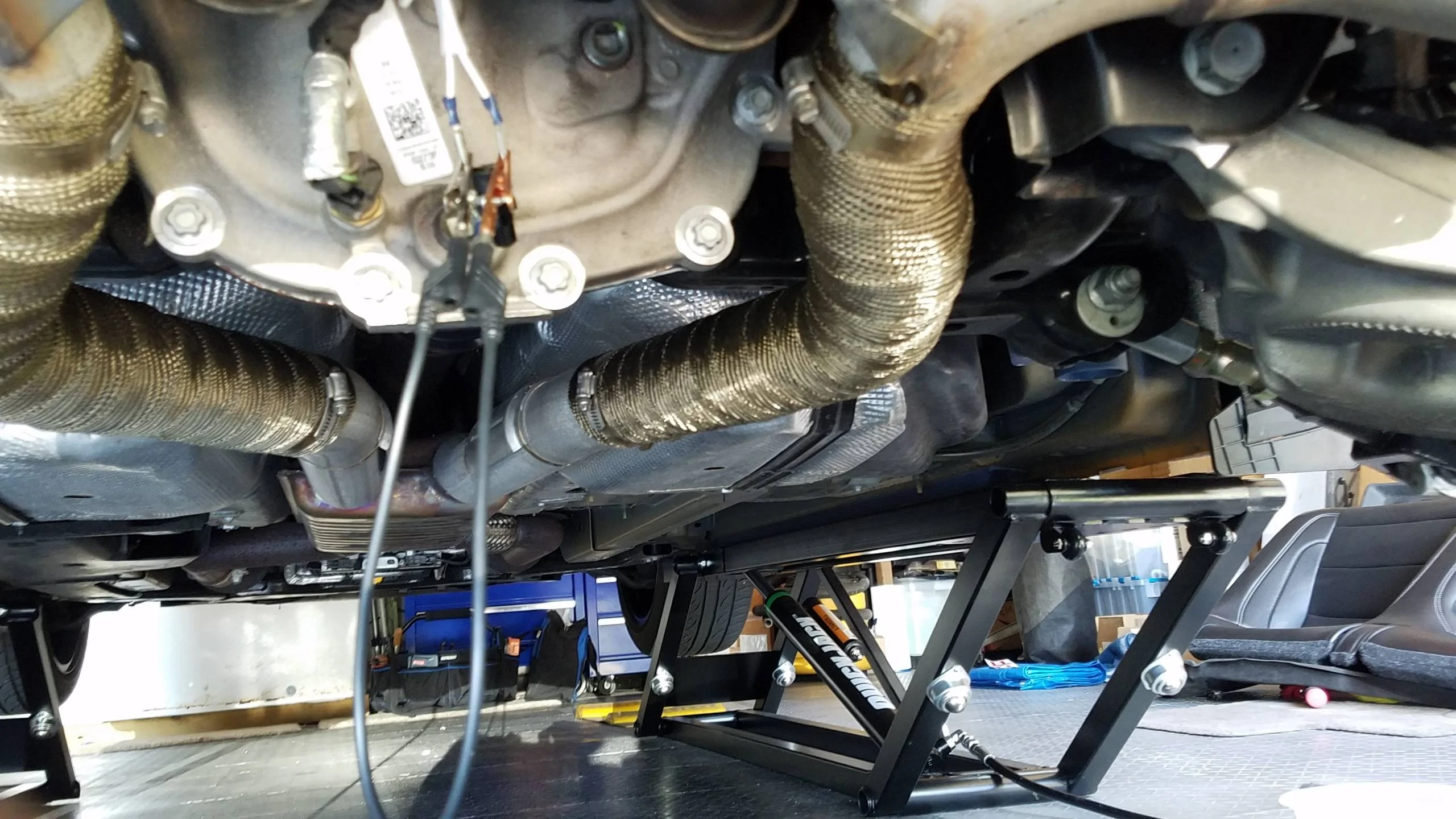
I had success on track running without a diff cooler by double-wrapping my exhaust near the differential, and running 140 weight gear oil
But I finally got the Axle Overtemp warning at the 32 minute mark during an open track day. So I decided to design a fan-less diff cooler.
I worked with the Setrab applications engineer via email over a few weeks. He advised that -6AN lines were sufficient as was their small ~1gmp pump. I agonized the most over which cooler to choose. I planned to bolt a wide, short cooler to the underside of the spare tire well in a lateral and vertical orientation. I settled on their 9-series 15-row cooler because its width spanned the flat spots of the body the best and had the most cooling rows without extending below the ground clearance plane of the car. I positioned it about halfway between the roll bar and black fuel system box.
I considered both flow directions of oil from the diff to the cooler then the pump, versus the diff to the pump and then the cooler. The reason for the latter scheme is only because the suction load is lower. I chose the former to run cooler oil to the pump, and after being assured by Setrab that the suction would be high enough.
Another interesting feature to my build is the Setrab thermo-switch. This 180F switch is rated at 10 amps. The pump draws about 1 amp, and is fused at only 3 amps. Therefore I saw no reason for the complexity of a full 5-wire relay setup. With crossed-fingers, I proceeded to build this fan-less and relay-less design.
Pretty much everything was available from Improved Racing. Here is the flow scheme:
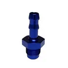
This setup uses only 4.5 feet of hose! I squirted some gear oil into the pump gears, then hooked up all the hoses. I rigged up 3/8” clear vinyl tubing, two -6AN/barb adapters, and a stainless salad bowl for the pump to prime the system. (To run the pump I only had to jumper the thermoswitch and switch on the car. Once oil came out of the second tube, I connected the supply-side hose to the diff lower port (i.e. swapping input and output), and further filled the diff to the proper level using the pump. Then I connected the two hoses as they should be.
Back to another open track day, I tested it out on a 45-minute run. Temp remained steady at 230F. Mission accomplished!
Detail of checkvalve, filter, hose2, hose3, and a supporting strap for 3-point cooler mounting.

The little Marco pump, and wiring harness passed through the rubber grommet.
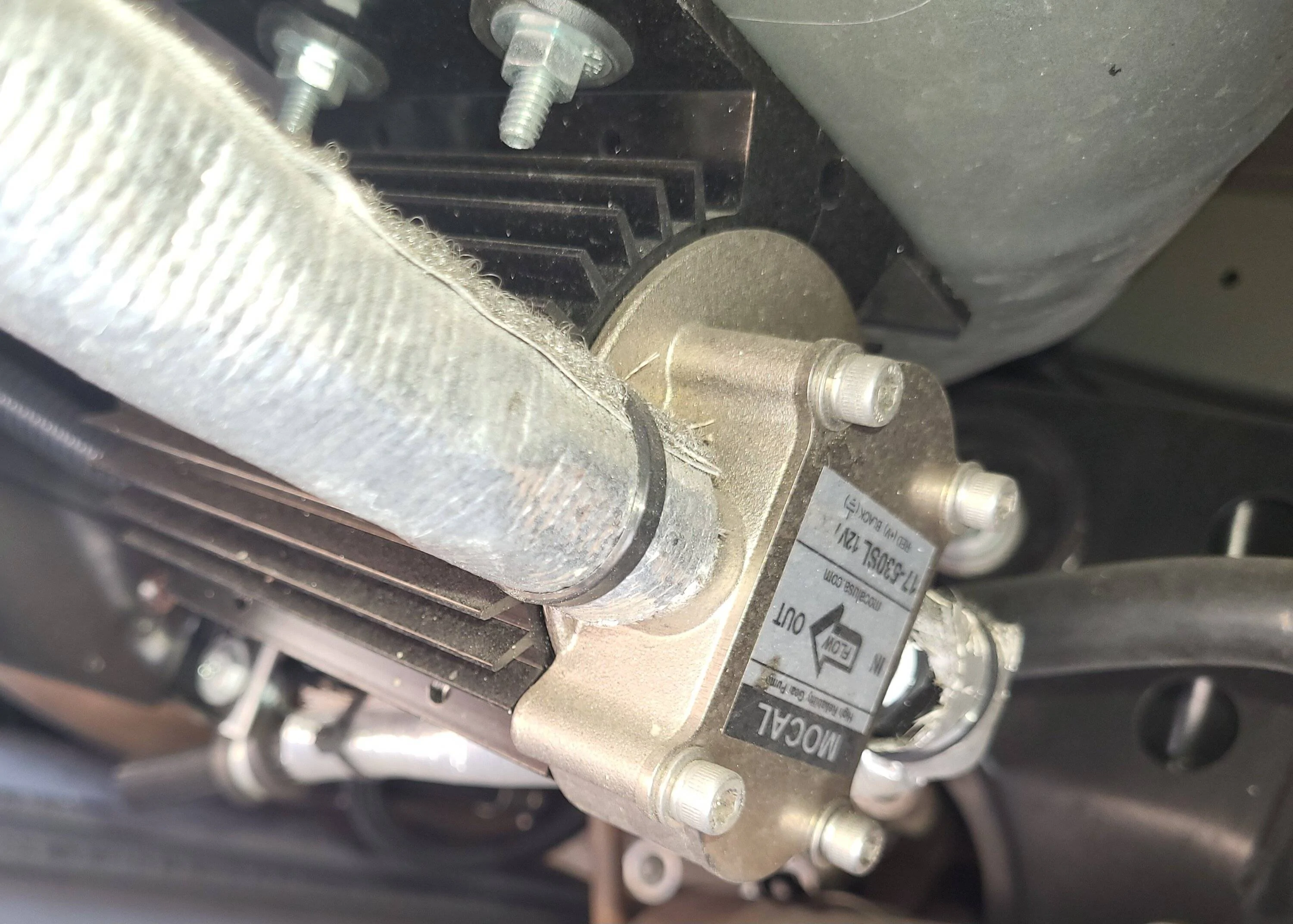
Thermoswitch, hose1, and hose4.
But I finally got the Axle Overtemp warning at the 32 minute mark during an open track day. So I decided to design a fan-less diff cooler.
I worked with the Setrab applications engineer via email over a few weeks. He advised that -6AN lines were sufficient as was their small ~1gmp pump. I agonized the most over which cooler to choose. I planned to bolt a wide, short cooler to the underside of the spare tire well in a lateral and vertical orientation. I settled on their 9-series 15-row cooler because its width spanned the flat spots of the body the best and had the most cooling rows without extending below the ground clearance plane of the car. I positioned it about halfway between the roll bar and black fuel system box.
I considered both flow directions of oil from the diff to the cooler then the pump, versus the diff to the pump and then the cooler. The reason for the latter scheme is only because the suction load is lower. I chose the former to run cooler oil to the pump, and after being assured by Setrab that the suction would be high enough.
Another interesting feature to my build is the Setrab thermo-switch. This 180F switch is rated at 10 amps. The pump draws about 1 amp, and is fused at only 3 amps. Therefore I saw no reason for the complexity of a full 5-wire relay setup. With crossed-fingers, I proceeded to build this fan-less and relay-less design.
Pretty much everything was available from Improved Racing. Here is the flow scheme:
- Diff lower port
- Temp switch
- Hose #1
- Check valve, flapper style
- 150-micron filter
- Hose #2
- Setrab 915 cooler
- Hose #3
- Marco pump
- Hose #4
- Diff upper port (I did not drill/tap a new fill port for the obvious reason.)
This setup uses only 4.5 feet of hose! I squirted some gear oil into the pump gears, then hooked up all the hoses. I rigged up 3/8” clear vinyl tubing, two -6AN/barb adapters, and a stainless salad bowl for the pump to prime the system. (To run the pump I only had to jumper the thermoswitch and switch on the car. Once oil came out of the second tube, I connected the supply-side hose to the diff lower port (i.e. swapping input and output), and further filled the diff to the proper level using the pump. Then I connected the two hoses as they should be.
Back to another open track day, I tested it out on a 45-minute run. Temp remained steady at 230F. Mission accomplished!
Detail of checkvalve, filter, hose2, hose3, and a supporting strap for 3-point cooler mounting.

The little Marco pump, and wiring harness passed through the rubber grommet.

Thermoswitch, hose1, and hose4.

Sponsored
Last edited:


![20230712_162143[1].webp](https://cdn.mustang6g.com/attachments/754/754387-36e191fb8dfaed4931d9e8ded678c919.webp)