StangTime
Well-Known Member
- Joined
- Apr 16, 2019
- Threads
- 81
- Messages
- 3,594
- Reaction score
- 4,093
- Location
- Ontario 🇨🇦
- First Name
- Todd
- Vehicle(s)
- 19' GT PP1 Manual
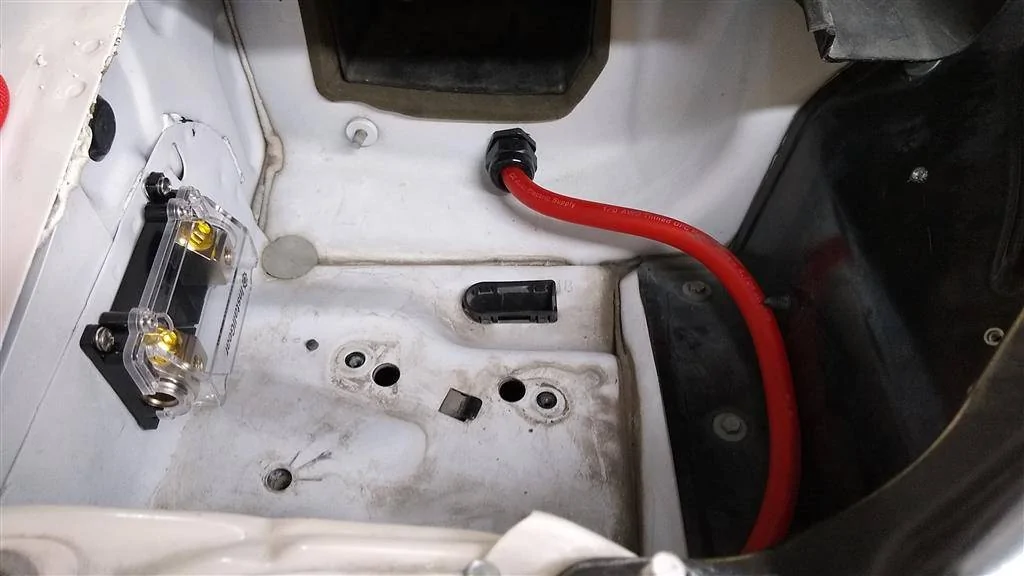
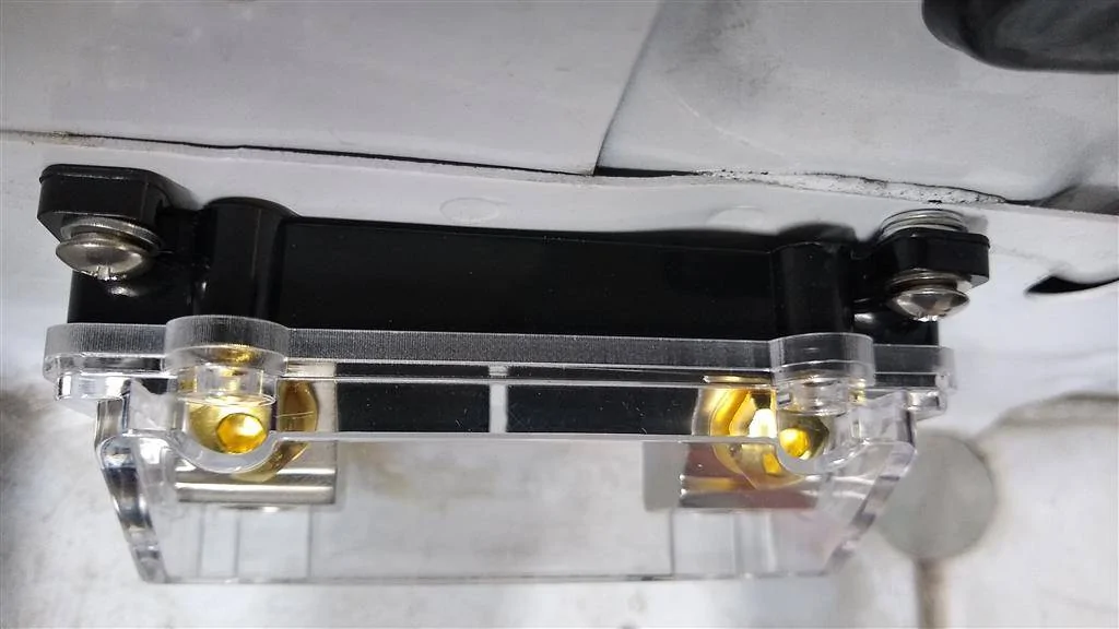
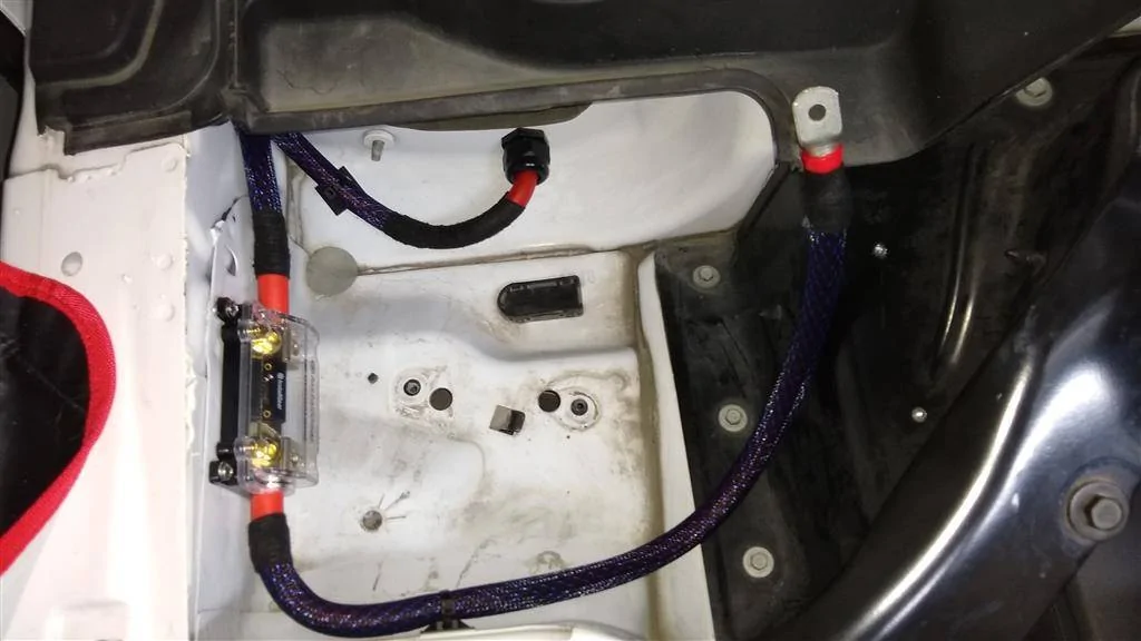
Yeah, I noticed your fuse block is for 0gauge. Much bigger. I would say you have a couple options. Maybe you can move it up so it's under the cross brace, protected from drips. Or move it down and further away from the firewall, away from the water. Fab-up some water shield that can be removed to get at the fuse. Or do what you suggested and put it between the battery box and the passenger fender side.Thanks for the pics and explanation. No way my fuse holder will fit where you put yours. My fuse holder is "waterproof" in that it's designed to get wet occasionally, but I definitely wouldn't want water pouring on it. I'll have to relook this. Thanks for the help.
Sponsored

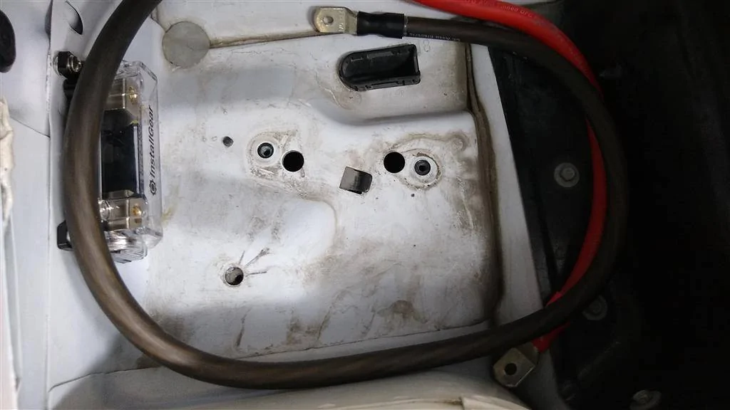
 It's well out of the way from where any water would be.