Sponsored

Installing aftermarket Gauges- where do electrical connections hook up?

steathv

Well-Known Member
Joined
Feb 1, 2022
Threads
5
Messages
106
Reaction score
94
Location
Lynchburg, VA
First Name
Chris
Vehicle(s)
2022 California Special
Working on hooking up the electrical connections for aftermarket gauges - GlowShift brand but applies to others as well. Need a 12 volt constant power source,
an ignition switched 12 volt power source and to the positive headlight switch power source using the passenger side fuse panel to do so. I have read many threads and have done much research but have not seen any specifics of which wire or terminals to tap into. A simple explanation of what to tap into would be helpful if anyone knows the answers even if not the passenger side fuse panel.

Reached out to the manufacturer and they do not know, which is somewhat odd to me. Any help is appreciated.

Thank you
Sponsored
 

Unas2k5

Well-Known Member
Joined
May 30, 2022
Threads
85
Messages
1,706
Reaction score
694
Location
Detroit
First Name
Samer
Vehicle(s)
2015 Mustang GT, 2021 Explorer ,2019 Impala
I wasn’t able to find anything either that’s why I don’t have a boost gauge lol
 

Snakebyte

Well-Known Member
Joined
Jun 26, 2020
Threads
6
Messages
1,088
Reaction score
1,256
Location
West Central Florida
First Name
Nathan
Vehicle(s)
2019 Mustang GT Convertible
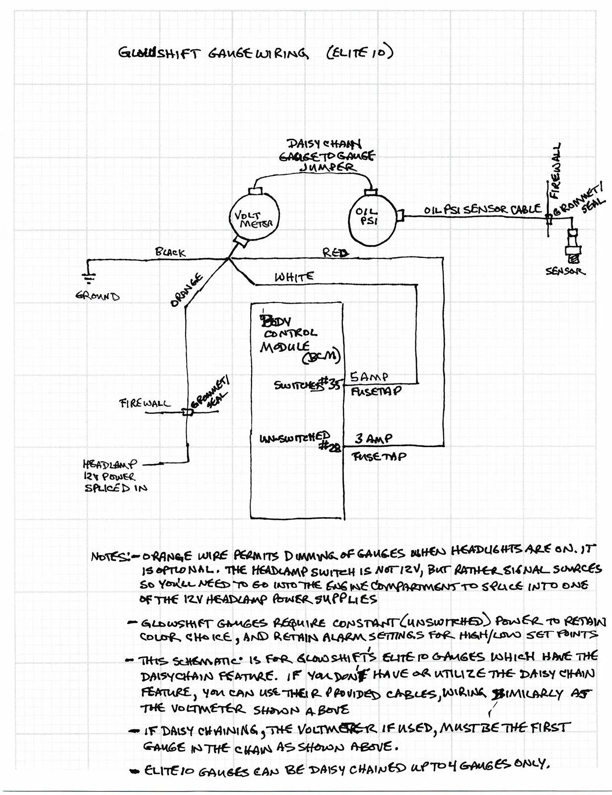
I'm installing glowshift gauges soon. Here's the schematic I developed. Hopefully I'll perform the installation Friday...we'll see how time goes.

Note that the schematic includes some common connection points with the bumper cam I recently installed. Hope you can find my schematic as a good starting point.

Though I included the 7.5 amp circuit between the BCM and headlamp switch, I'm really just looking for the yellow wire in-between those two components to trigger my nighttime dimming.

Side note...I purchased GlowShift Elite 10 gauges which permits daisy chaining from the first gauge (volt meter) on to subsequent Elite 10 gauges. Your needs may differ if you got one of the other gauges. However the principle should be the same.

I am using micro fuse taps. Note that the one required for circuit 25 is a Micro2 and the one for circuit 22 is a Micro3 Tap

Okay everyone...my install is complete and here's an update to my schematic, based on the challenges I found. The two main challenges I found were:
a) The #22 micro3 circuit fuse-tap was not physically workable. So I used a fuse tap to unswitched power fuse #28.
b) The yellow wire between the BCM and the headlamp switch is a control circuit, and not a 12v circuit, so I had to locate a 12v headlamp power wire.

In the edited schematic I show two different firewall penetrations, one for the oil sensor wire and the other for the headlamp power splice, but of course you can use the same firewall penetration.

GlowShift Elite 10 Wiring.webp
 
Last edited:

Ewheels

Well-Known Member
Joined
Apr 5, 2019
Threads
69
Messages
1,932
Reaction score
2,749
Location
SoCal
First Name
Eric
Vehicle(s)
'18 GT PP1, '23 F150, '24 4Runner Pro
Vehicle Showcase
1
When I did my Autometer oil temp gauge, I used an add-a-line fuse tap on fuse #23 in the passenger fuse box and grounded in the same area.

Let me know if you have other questions. I'll help however I can.
 

5doorsoffury

Well-Known Member
Joined
Jun 26, 2022
Threads
3
Messages
245
Reaction score
305
Location
a forsaken branch of the wavefunction called ny,
First Name
this guy
Vehicle(s)
mustang gt
So I was remote start audio installer for about 15 years and I was pretty pissed to find out it's all data controlled ignition like a gm.... so this is what I did, I needed to run intercooler pump gauges and a bunch of other shit so I took the ignition output which is low current in the passenger kick and I threw a relay on there then I wired to fly back diode on the relay then I put a thousand microfarad cap on the relays coil feed to keep it from shutting off during cranking and now the relay feed from a constant Source in the kick and I can switch as much crap as I want as well as send that ignition signal anywhere in the car for other stuff.
12v relay= 30 to hot, 95 to ing, 96 to gnd and 87 is the output for the stuff. my cap was wired to 95 and gnd. I added a diode between the cap and ing feed to prevent backfeeding. the fly back was wired backwards to current flow (forgot if anode or cathode lol)on 95, 96.
The best part about it is if all my accessories aren't working that I wired up I know for sure my intercooler pump isn't working so that's an indicator for me and that would be my main worry that way I can catch it before I wonder why my bats aren't getting better
 

Sponsored

OP
OP

steathv

Well-Known Member
Joined
Feb 1, 2022
Threads
5
Messages
106
Reaction score
94
Location
Lynchburg, VA
First Name
Chris
Vehicle(s)
2022 California Special
Snakebyte, let me know how the install goes, looks logical to me if you have the correct fuse taps.
The problem all along has been figuring the correct taps. From research have seen #2 for constant, #18 or 23 for switched and pin 15 violet wire off headlamp switch for dimming as possibilities.

Thank you
 

Snakebyte

Well-Known Member
Joined
Jun 26, 2020
Threads
6
Messages
1,088
Reaction score
1,256
Location
West Central Florida
First Name
Nathan
Vehicle(s)
2019 Mustang GT Convertible
You guys need to get yourselves a Power Probe. This way you can check for yourselves which fuses are always hot or hot only when the ignition is on.

https://www.amazon.com/Power-Probe-...3&keywords=power+probe&qid=1717620713&sr=8-10
The probe is a great tool, and I do recommend it for diagnosing especially. I also use a very good electric meter/amp clamp. Of course they all have their place, depending on what you are doing, even if it is minor work. But then, if a person is not aware of what he/she is doing, you can inadvertently blow a fuse if you're not careful, or are electrically handicapped. :cool: .......and that is one good reason for vehicles having fuses, right? (Better than burning a car to the ground.)
For repair and project planning, I purchased a Ford-authorized manual on DVD when I purchased my Mustang. For most people, that is far too detailed. (And it's not even close to being as good as the old paper Helms manuals I've been accustomed to over the years.)

Anyway, as for the fuse numbers I chose to use spares for my fuse taps. Indeed you can use most other BCM fuses, switched or unswitched, if you are using fuse taps. But my preference is spares when possible.
 

mookieit

Well-Known Member
Joined
Feb 6, 2022
Threads
70
Messages
250
Reaction score
124
Location
tampa
First Name
john
Vehicle(s)
mustang 2015 v6
I'm installing glowshift gauges soon. Here's the schematic I developed. Hopefully I'll perform the installation Friday...we'll see how time goes.

Note that the schematic includes some common connection points with the bumper cam I recently installed. Hope you can find my schematic as a good starting point.

Though I included the 7.5 amp circuit between the BCM and headlamp switch, I'm really just looking for the yellow wire in-between those two components to trigger my nighttime dimming.

Side note...I purchased GlowShift Elite 10 gauges which permits daisy chaining from the first gauge (volt meter) on to subsequent Elite 10 gauges. Your needs may differ if you got one of the other gauges. However the principle should be the same.

I am using micro fuse taps. Note that the one required for circuit 25 is a Micro2 and the one for circuit 22 is a Micro3 Tap

Okay everyone...my install is complete and here's an update to my schematic, based on the challenges I found. The two main challenges I found were:
a) The #22 micro3 circuit fuse-tap was not physically workable. So I used a fuse tap to unswitched power fuse #28.
b) The yellow wire between the BCM and the headlamp switch is a control circuit, and not a 12v circuit, so I had to locate a 12v headlamp power wire.

In the edited schematic I show two different firewall penetrations, one for the oil sensor wire and the other for the headlamp power splice, but of course you can use the same firewall penetration.

GlowShift Elite 10 Wiring.jpg
Can you share bit more details about the orange wire? Witch one is the headlight power?
 

Snakebyte

Well-Known Member
Joined
Jun 26, 2020
Threads
6
Messages
1,088
Reaction score
1,256
Location
West Central Florida
First Name
Nathan
Vehicle(s)
2019 Mustang GT Convertible
Can you share bit more details about the orange wire? Witch one is the headlight power?
To avoid having to pierce through the firewall again, I installed a "hidden" push-on/push-off switch in the AC thermostat sensor panel (to the right of the steering column).
In hindsight I wish I'd not wired for the dimming feature. I never use that feature as in daylight the bright illumination is needed and at night the backlight is not overly bright as I imagined it was going to be. (I have the darkened gauge faces which ultimately reduces the brightness.) I really wish I'd have gotten gauges without the dark face. If I had, then yes, the night dimming would have been beneficial.)
Sponsored


Top