Sponsored
engineermike
Well-Known Member
Yes, but is it accurate for your location?Didn't we have me set baro to 30?
Also, that’s temporary until you get the inferred model working right. The isolated mapped points and disabled etc pid feedback loop are also temporary.
OP
OP
tdstuart
Well-Known Member
- Thread starter
- #948
According to online its 29.73Yes, but is it accurate for your location?
Also, that’s temporary until you get the inferred model working right. The isolated mapped points and disabled etc pid feedback loop are also temporary.
And okay. I am going to update the SD model and see what the car says
engineermike
Well-Known Member
I wouldn’t turn the inferred baro back on until all your speed density models are tuned and tested.
Sponsored
engineermike
Well-Known Member
I was just checking.Is it on? I think I just have baro set to 30
K4fxd
Well-Known Member
Looked pretty close to me. Get rid of the cam and IMRC channels. If you haven't already, set the resolution to the highest setting on the air PID's.looks way off still.
I think you are seeing scanner lag.
markmurfie
Well-Known Member
Have you tried setting the air charge multiplier table to the maximum air load you are seeing in that MAP? This is for making MAF and desired MAF line up. It may have an effect on the TP MAP estimate and calculated MAP lining up as well.Here is with corrected data. Log and tune attached, looks way off still.
I believe the maximum load at WOT tables are the ones that don't do anything, but I get which is which mixed up all the time because of the labels and table descriptions.
A lot of this desired load, desired MAF comes from a desired torque value. If the air just isn't physically in the engine it's never going to meet that torque demand, and the entire rest of the chain is going to be off.

Last edited:
markmurfie
Well-Known Member
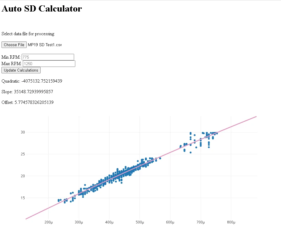
The patterns based on RPM you can quickly see calculated MAP vs Estimated MAP with this is good. MP 19 corrected calculated MAP(left) vs Estimated MAP(right), eliminating points from lower RPMS going to higher RPMS.Here is an updated version that includes a graph (graph requires internet for external API):

Remove some of the lower RPMS.

Removing more of the lower RPMs and you can see how the calculated and TB are showing the same pattern just in slightly different ways.

SD is falling back to the 100% VE line at the higher RPMS. The TB model is doing the same thing.
Im pretty sure they are very close in agreement and the 100% VE airmass as stated in my post above just needs to be limited to make them totally agree. both limited to .00095lb airmass(.56 airload) maximum and they would be nearly identical.
Sponsored
Pistol_91
Well-Known Member
- Joined
- Oct 25, 2023
- Threads
- 13
- Messages
- 1,431
- Reaction score
- 1,456
- Location
- Clearwater
- Vehicle(s)
- 2020 mustang GT
What is this auto SD calculator you guys are using? Something murf made?
Mach VII
Well-Known Member
- Joined
- Mar 22, 2017
- Threads
- 15
- Messages
- 1,161
- Reaction score
- 2,665
- Location
- Berkshire Hills, MA
- First Name
- John
- Vehicle(s)
- 2019 Mustang GT 401A, 1989 Lincoln Mk VII LSC
https://www.mustang6g.com/forums/threads/tdstuart-tuning-adventure.201824/post-4073334What is this auto SD calculator you guys are using? Something murf made?
OP
OP
tdstuart
Well-Known Member
- Thread starter
- #958
Ill try this and report back. I was just comparing the MAP vs TB Estimated MAP.Have you tried setting the air charge multiplier table to the maximum air load you are seeing in that MAP? This is for making MAF and desired MAF line up. It may have an effect on the TP MAP estimate and calculated MAP lining up as well.
I believe the maximum load at WOT tables are the ones that don't do anything, but I get which is which mixed up all the time because of the labels and table descriptions.
A lot of this desired load, desired MAF comes from a desired torque value. If the air just isn't physically in the engine it's never going to meet that torque demand, and the entire rest of the chain is going to be off.

engineermike
Well-Known Member
Let's take a snapshot of the last log:

At that moment in time, the SD-model MAP is 7.9 psia.
At the same moment, the TP Model MAP is 21.22 inHg, which is 10.4 psia. Let's assume the TB model, baro, and MAF are accurate, therefore this number is accurate.
The SD-model MAP is used to determine the throttle blade angle. At that time, the throttle body deltaP is 14.7 - 7.9 = 6.8 psid. So it moves the throttle to an angle where it expects to get 19.04 lb/min airflow at that dP. However, the resulting airflow is only 14.24 lb/min.
If the SD-model MAP were 10.4 psia to match the TP-model MAP, then the throttle body dP would be 4.3 psid. With only 4.3 psi pressure difference, the throttle body would be commanded to open more to get the desired airflow, and the MAF would match the desired MAF better.
Therefore, if the SD-model MAP were higher, to match the TP Model MAP, then the throttle would open more, and the MAF would match the Desired Airmass closer and you're make roughly 25% more torque at that pedal position.
Doing some quick and dirty flow math, if you ratio the square root of the SDdp and the TPdp, and multiply by the 14.24 lb/min, you get 19.3 lb/min, which is very close to the 19.04 it desires. That backs up the case that if the models match, then the flow would also match.
In summary, I think the SD model needs more work. I do believe the TP model and SD model MAPs can be tuned to match well up to about .5 load at low rpm and .8 or so at high rpm. At that point, opening the throttle further won't result in any more load.
Last edited: