mikes2017gt
Well-Known Member
- Joined
- Feb 21, 2017
- Threads
- 64
- Messages
- 999
- Reaction score
- 343
- Location
- San Antonio, TX
- Vehicle(s)
- 17 GT Prem M/T 3.55
- Thread starter
- #1
This is a "Work In Progress Thread" vs. a "It's all done and here's my build thread" thread. It will keep me motivated to keep going!
Back in 2017 I said I was happy enough with the stock 9-speaker Shaker + Stealthbox install. It was good enough, and I wasn't going to deal with the misery of a full install ever again. But you know, things change. I wanted more midbass punch, more bass, more SPL overall and more tuning ability than the bass/mid/treble controls on the HU. But I wasn't going to give up my trunk. Been there many times and not going back.
This used to be "the system." The sub isn't going anywhere, but the spare tire well is going to see some big changes.

In short: I made the decision to go full active 3-ways in the front doors, sound treat the heck out of the doors and the rear deck, lose the rear speakers to allow bass into the cabin, lose the dash center driver, keep the Stealthbox (and my trunk space) and use a DSP for all the crossover/EQ/time alignment duties.
Here's a list of everything I'm doing, equipment, settings, etc. Some of this is done already as of 15 Sep...most of it isn't. I have already purchased everything I need, down to the fuses, connectors, etc.
Head Unit/Signal Processing:
Stock 400A HU, using just the front channel outputs via soldered-on RCAs from the (color) plug that goes into the amp. Forscan tweak to remove all signal processing.
JL Audio TWK-88 (Crossover/EQ/time-alignment)
Amps:
Midbass/Tweeters: JL Audio XD600/6v2 (75W x 6 @ 4 ohms or 150W x 3 bridged @ 4 ohms) Running 4 channels bridged for L/R midbasses, 2 channels L/R for tweets.
Mids: JL Audio XD200/2v2 (75W x 2 @ 4 ohms)
Sub: JL Audio XD600/1v2 (600w @ 2 ohms)
Speakers:
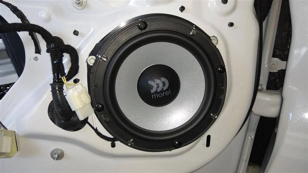
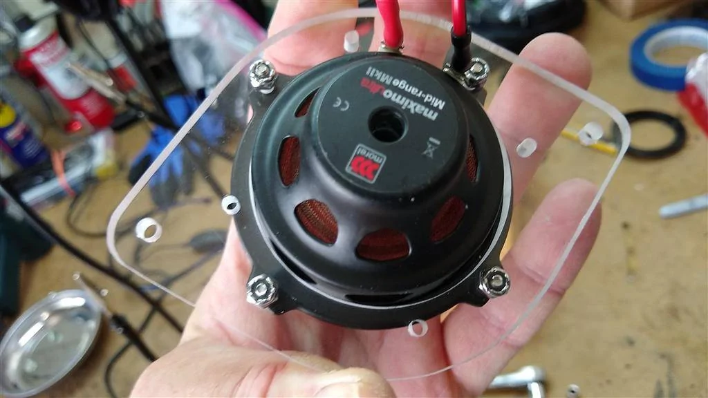
Fronts - Morel Maxmimo Ultra 603 3-way component set
Sub - JL Audio Stealthbox SB-F-MUSCPE/12TW3 (dual 4-ohm driver, wired for 2 ohms). Moderately stuffed with Polyfil--comes empty from the factory
Rears/Center Channel - Disconnected, like they should be. Rear Speakers removed to facilitate bass transfer into cabin
Wiring/other:
iDatalink HRN-AR-FO3 9 harness (just using the 3 Molex plugs and the wires I need; cut off everything else)
14-gauge speaker wire from amps up to drivers' kick panel--output to door speakers via Molex plugs/vehicle wiring--tweets have dedicated 14-ga runs
Double-Shielded RCAs all around
0-gauge OFC main power/ground, 150-amp ANL fuse under hood, 4ga OFC power/ground (amps), mini-ANL fuse block in trunk
0-gauge battery ground to body ground upgrade
Power wire ran down passenger side, signal/TO/speaker wires down drivers' side
PAC TR-4 turn on module using 6V audio enable (turn on) signal from HU to switch +12V for TO signal
1A fuse on 6V turn on wire from HU, 1A fuse on switched 12V
Ferrules on all power and speaker wires
Tessa tape and/or flex loom on all cables and wires
Dynamat Xtreme on trunk/spare tire area/wheel tubs/rear deck/trunk lid
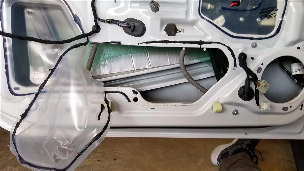
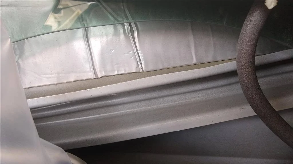
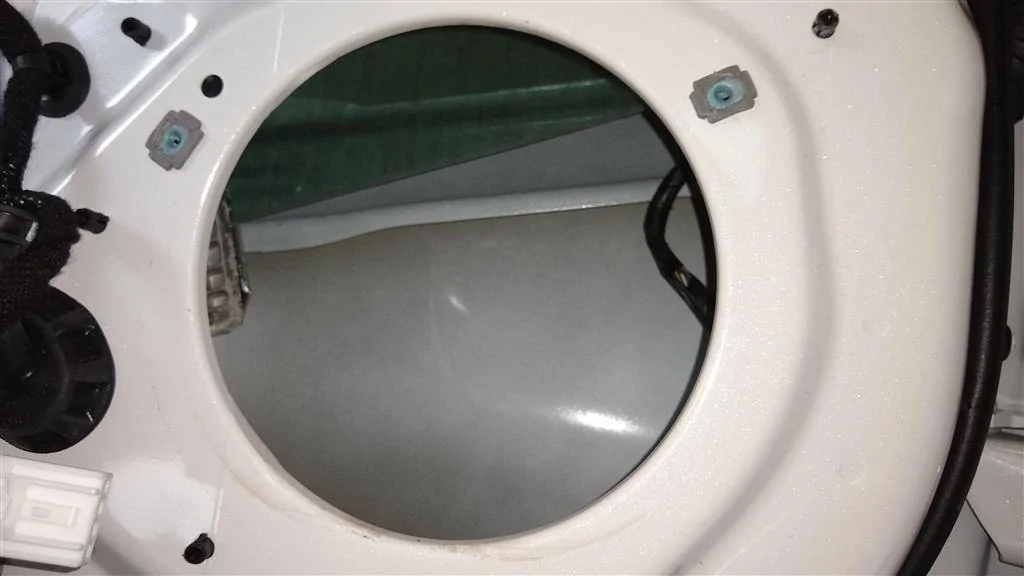
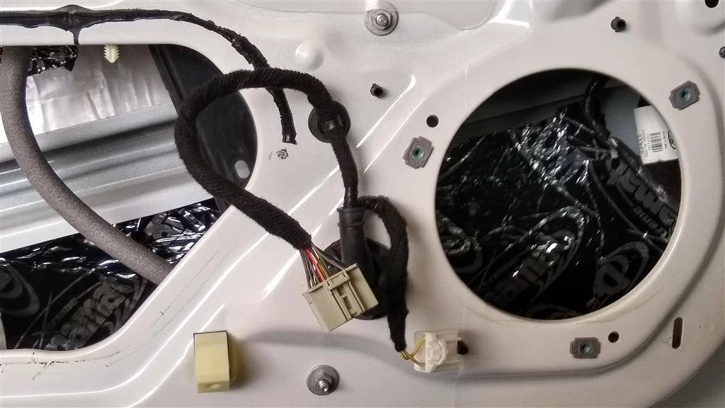
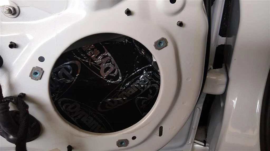
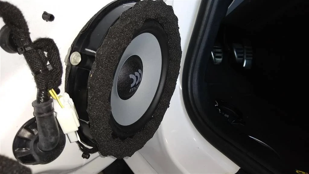
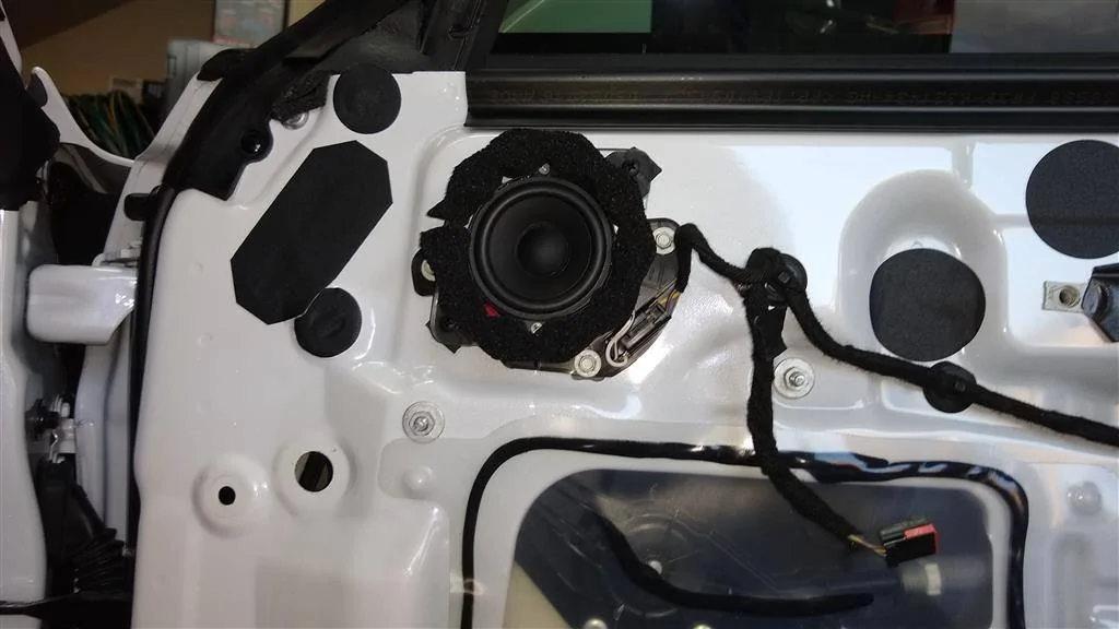
Dynamat Xtreme on front doors, mostly behind and around the midbass driver on outer door skin
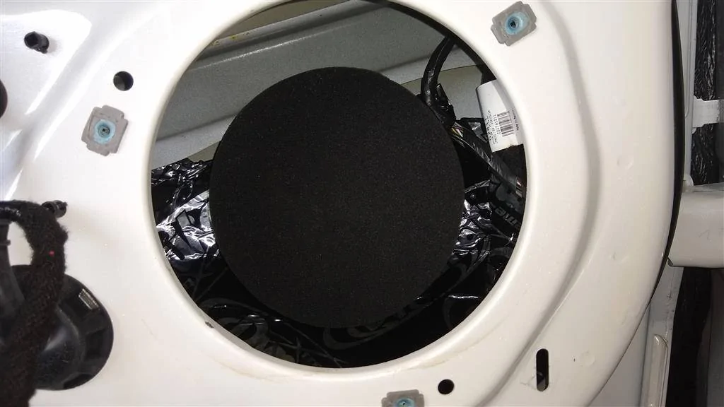
Fast Rings on midbasses and mids
Metra 82-5605 adapter rings and 72-5602 Wiring Harness for midbass drivers
T-taps for mids (no cut harnesses)
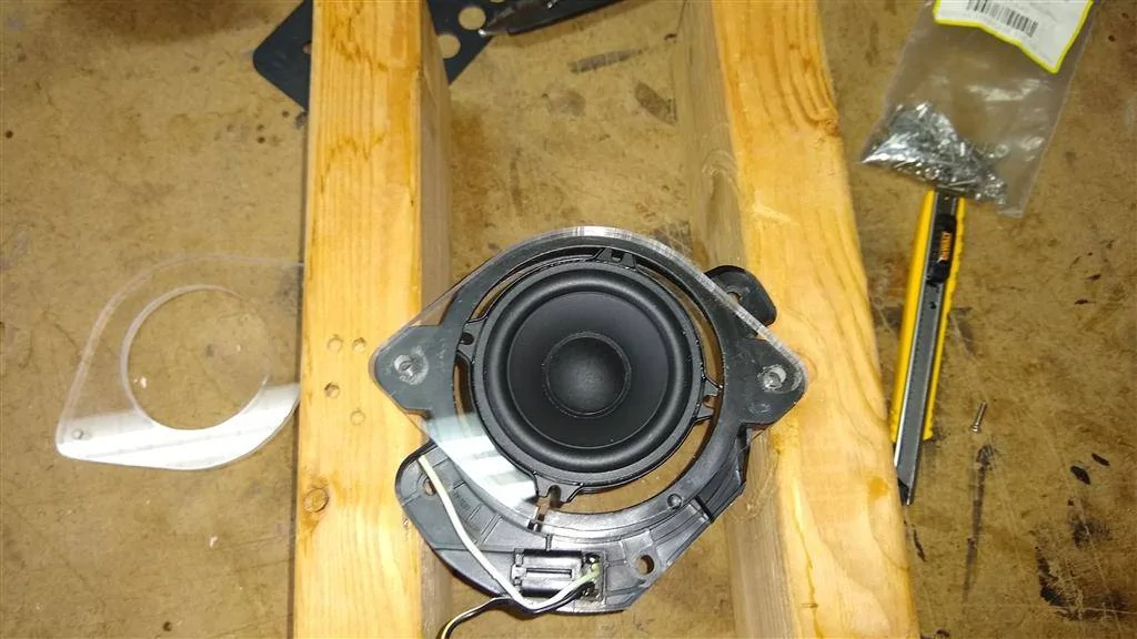
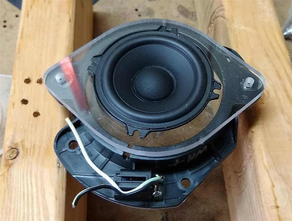
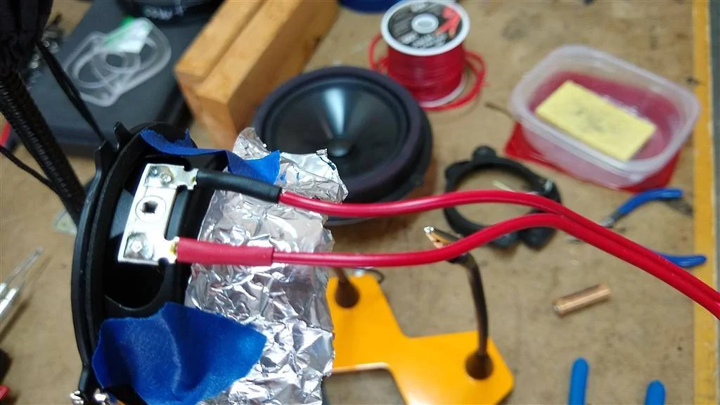
Custom acrylic adapter rings for Morel midrange drivers
A-pillars modified to fit Morel tweeters
Speaker gasket tape on all speaker/bracket mounting surfaces
Settings for active crossover (baseline). NOTE: The values listed below are directly from Morel tech support, via Crutchfield's tech support. The passive xovers/instructions that come with the set don't list what frequencies/slopes it uses. I attempted to contact Morel tech support twice and received no response, which is a real bummer. But Crutchfield was very helpful and contacted Morel for me and got the info. Highly recommend buying from Crutchfield. You might pay a little more, but you know you're buying from an authorized dealer and can get support if you need it. They were very helpful.
Tweeter
Highpass - 4500Hz @ 24dB (range 3200Hz - 5000Hz)
Midrange
Lowpass -4500Hz @ 24dB (range 3200Hz - 5000Hz)
Highpass -450Hz @ 24dB (range 350Hz - 700Hz)
Midbass
Lowpass -450Hz @ 24dB (range 350Hz - 700Hz)
Highpass - 90Hz @ 24dB (range 70Hz - 120Hz)
Sub
Lowpass -90Hz @ 24db
Highpass - 35Hz @24db
Easy stuff first. I deadened the trunk lid.
Before

After (I used the scrap cutoffs inside the upper cavity, near the backup cam)
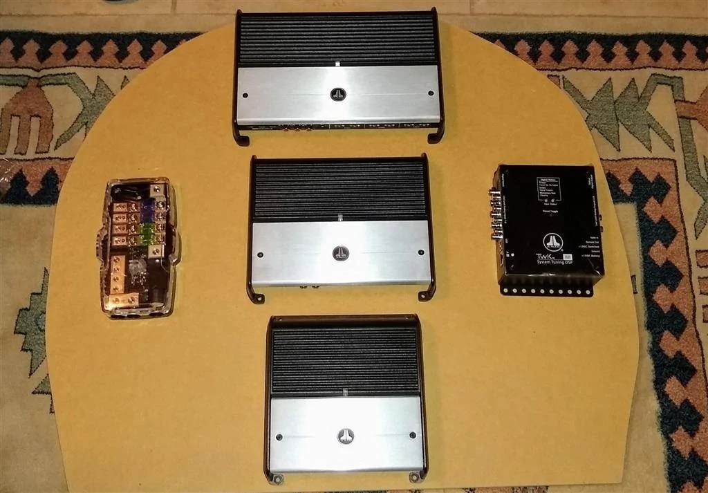
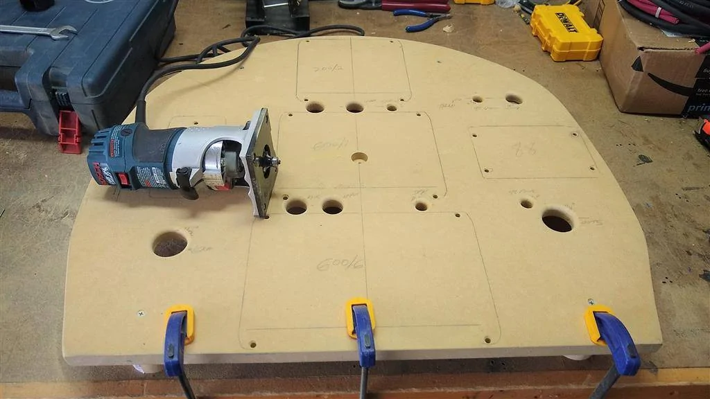
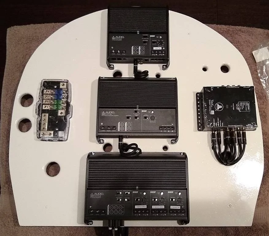
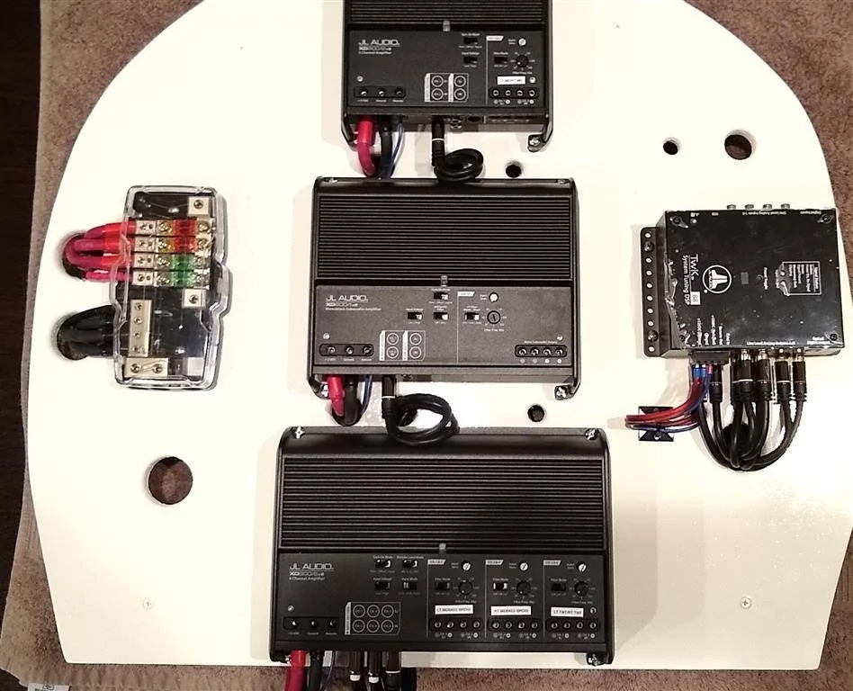
Next, I figured I'd build the amp rack. Board is 3/4" MDF, 24" from top to bottom and roughly 26" at it's widest point. I cut out my shape and laid out the components. There's a very good reason they are laid out this way. The amps all have their power inputs on the left side--the distro block is on the left side. The amps all have signal input in the middle--RCAs run up the middle (under the board). Speaker outs will run straight down the middle, under the board. I've never had an issue having speaker outputs cross over RCA inputs, but have definitely had issues when RCA inputs come anywhere near power inputs. Except for the speaker outputs crossing the RCAs at right angles, all power/signal/output wires will be separated as far from each other as possible.

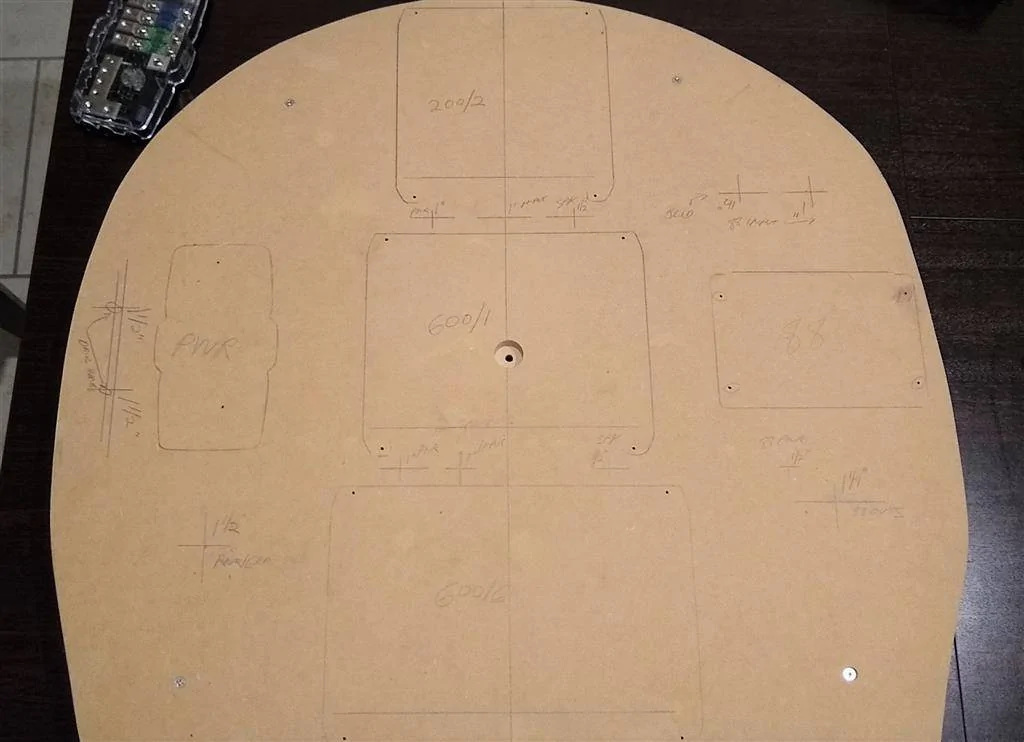
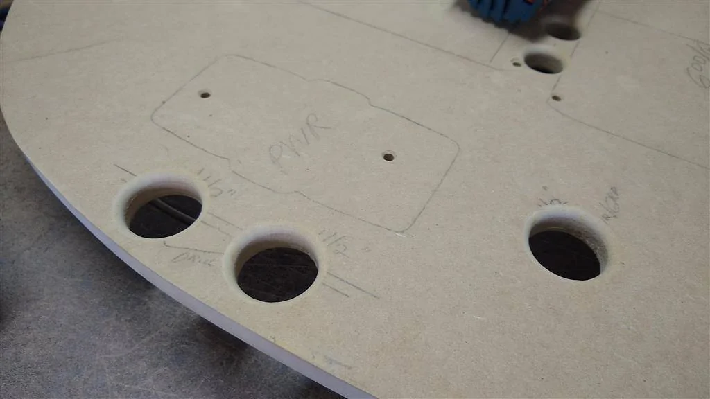
Traced around all the components and marked for drilling holes. That countersunk center hole is where the board mounts to the spare tire mount. Take the time to do this step right. Note I double-marked the component mounting holes with a black marker for emphasis. Mark all your drill points clearly...write little notes if you have to, it'll all be covered later. Nothing is worse than getting to this point and screwing it up by drilling the wrong size holes or off-center holes.

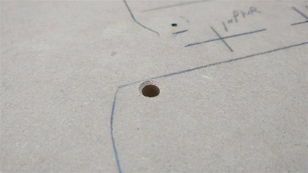
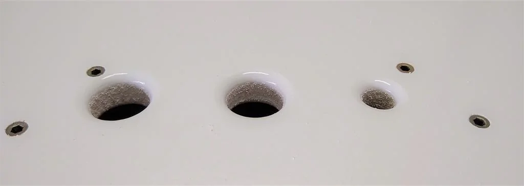
Drilled the holes for wiring, including countersunk holes for threaded inserts and rounded over the wiring holes with a 1/4" roundover bit.
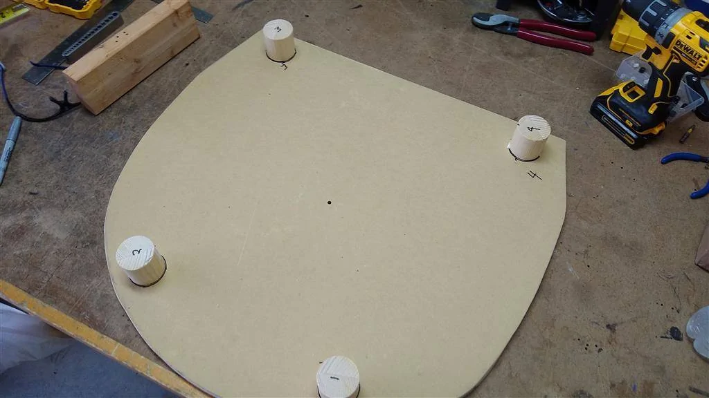
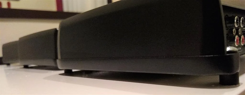
A bit out of order here, but the amp rack has feet. It sits flat on the spare well floor, about a 1/4" above the spare mounting bracket. Feet are 1-1/8" dowel rod from Home Depot. All feet are exactly 2" long.
Next up was painting the board. 8 or 9 coats of Krylon Gloss White and two coats of Rustoleum Gloss Clearcoat later. The threaded inserts are also installed here.


Mounted all the components and wired up the DSP to Amps signal wires. Everything but the distro block is sitting on 1/4" spacers I sprayed black (in the little box here).

Space under amps and TWK-88 for cooling.


Underside. At the top center, you'll see the RCAs go into Y-splitters. That's b/c I'm bridging two channels on the 600/6 for the midbasses. JL tech support told me that when bridging, you need to supply input to both the L/R inputs of each channel. So here I created "two lefts and two rights" with 2 Y-splitters. Signal (except for the input from HU) is done, and Power will be done before installing the rack into the trunk.

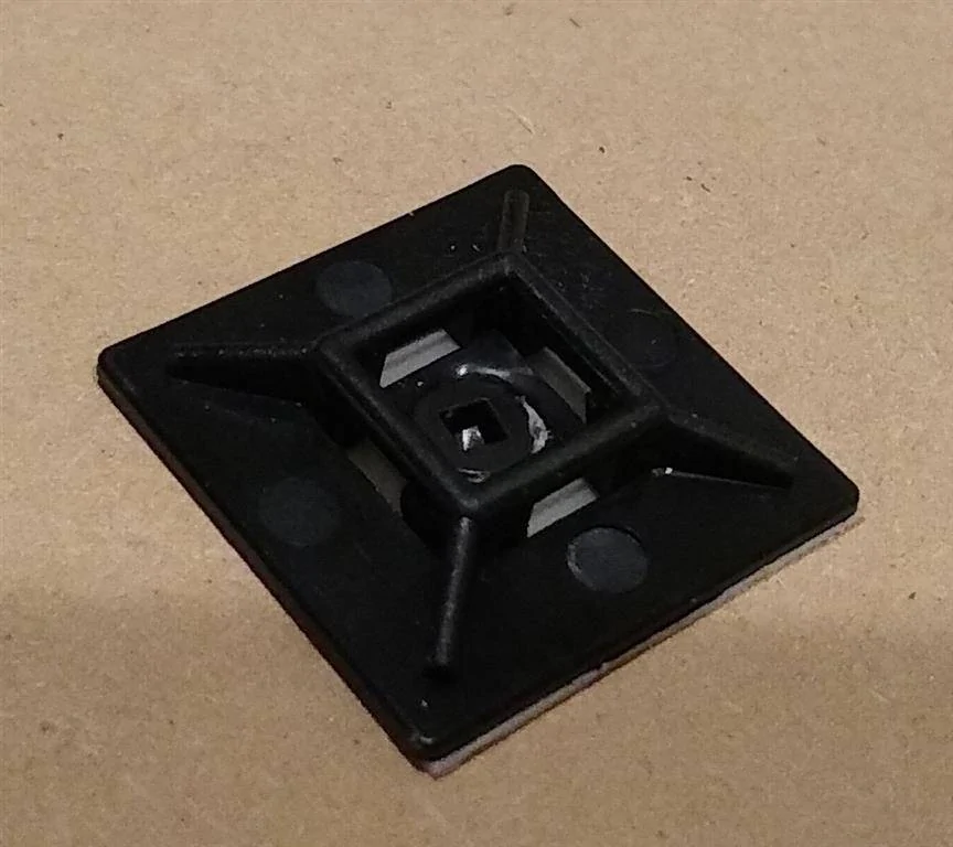
Using peel and stick zip tie bases with a screw driven in. Been using this cable management method for years and never had one move.

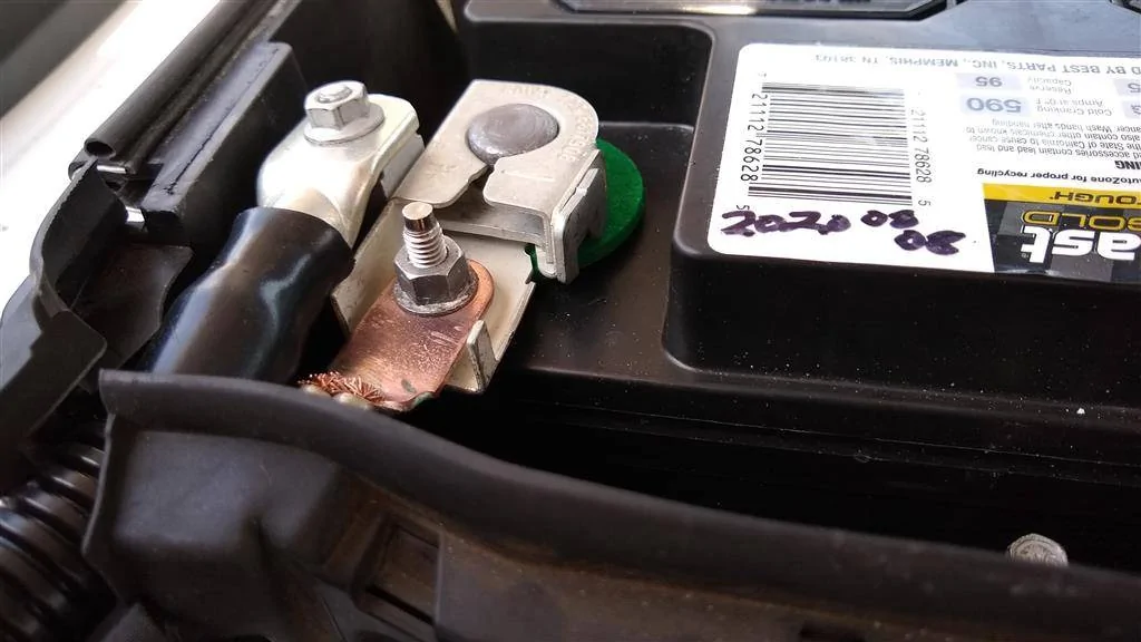
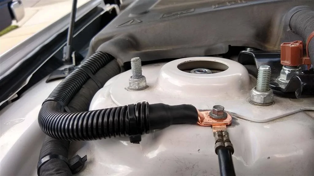
0-gauge body ground upgrade. Not exactly a "Big 3" but sure is an upgrade to the 6-gauge-looking factory ground underneath the shock tower terminal! In the last pic, you can see I sanded off the paint to ensure a better ground. I have since coated the exposed metal with clear nail polish. My wife will never know she contributed to this build...
So that's where we are right now. Still a lot of work to do. Thanks for joining me on this adventure!
Back in 2017 I said I was happy enough with the stock 9-speaker Shaker + Stealthbox install. It was good enough, and I wasn't going to deal with the misery of a full install ever again. But you know, things change.
I wanted more midbass punch, more bass, more SPL overall and more tuning ability than the bass/mid/treble controls on the HU. But I wasn't going to give up my trunk. Been there many times and not going back.This used to be "the system." The sub isn't going anywhere, but the spare tire well is going to see some big changes.

In short: I made the decision to go full active 3-ways in the front doors, sound treat the heck out of the doors and the rear deck, lose the rear speakers to allow bass into the cabin, lose the dash center driver, keep the Stealthbox (and my trunk space) and use a DSP for all the crossover/EQ/time alignment duties.
Here's a list of everything I'm doing, equipment, settings, etc. Some of this is done already as of 15 Sep...most of it isn't. I have already purchased everything I need, down to the fuses, connectors, etc.
Head Unit/Signal Processing:
Stock 400A HU, using just the front channel outputs via soldered-on RCAs from the (color) plug that goes into the amp. Forscan tweak to remove all signal processing.
JL Audio TWK-88 (Crossover/EQ/time-alignment)
Amps:
Midbass/Tweeters: JL Audio XD600/6v2 (75W x 6 @ 4 ohms or 150W x 3 bridged @ 4 ohms) Running 4 channels bridged for L/R midbasses, 2 channels L/R for tweets.
Mids: JL Audio XD200/2v2 (75W x 2 @ 4 ohms)
Sub: JL Audio XD600/1v2 (600w @ 2 ohms)
Speakers:
Fronts - Morel Maxmimo Ultra 603 3-way component set
Sub - JL Audio Stealthbox SB-F-MUSCPE/12TW3 (dual 4-ohm driver, wired for 2 ohms). Moderately stuffed with Polyfil--comes empty from the factory
Rears/Center Channel - Disconnected, like they should be. Rear Speakers removed to facilitate bass transfer into cabin
Wiring/other:
iDatalink HRN-AR-FO3 9 harness (just using the 3 Molex plugs and the wires I need; cut off everything else)
14-gauge speaker wire from amps up to drivers' kick panel--output to door speakers via Molex plugs/vehicle wiring--tweets have dedicated 14-ga runs
Double-Shielded RCAs all around
0-gauge OFC main power/ground, 150-amp ANL fuse under hood, 4ga OFC power/ground (amps), mini-ANL fuse block in trunk
0-gauge battery ground to body ground upgrade
Power wire ran down passenger side, signal/TO/speaker wires down drivers' side
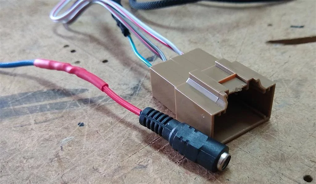
PAC TR-4 turn on module using 6V audio enable (turn on) signal from HU to switch +12V for TO signal
1A fuse on 6V turn on wire from HU, 1A fuse on switched 12V
Ferrules on all power and speaker wires
Tessa tape and/or flex loom on all cables and wires
Dynamat Xtreme on trunk/spare tire area/wheel tubs/rear deck/trunk lid
Dynamat Xtreme on front doors, mostly behind and around the midbass driver on outer door skin
Fast Rings on midbasses and mids
Metra 82-5605 adapter rings and 72-5602 Wiring Harness for midbass drivers
T-taps for mids (no cut harnesses)
Custom acrylic adapter rings for Morel midrange drivers
A-pillars modified to fit Morel tweeters
Speaker gasket tape on all speaker/bracket mounting surfaces
Settings for active crossover (baseline). NOTE: The values listed below are directly from Morel tech support, via Crutchfield's tech support. The passive xovers/instructions that come with the set don't list what frequencies/slopes it uses. I attempted to contact Morel tech support twice and received no response, which is a real bummer. But Crutchfield was very helpful and contacted Morel for me and got the info. Highly recommend buying from Crutchfield. You might pay a little more, but you know you're buying from an authorized dealer and can get support if you need it. They were very helpful.
Tweeter
Highpass - 4500Hz @ 24dB (range 3200Hz - 5000Hz)
Midrange
Lowpass -4500Hz @ 24dB (range 3200Hz - 5000Hz)
Highpass -450Hz @ 24dB (range 350Hz - 700Hz)
Midbass
Lowpass -450Hz @ 24dB (range 350Hz - 700Hz)
Highpass - 90Hz @ 24dB (range 70Hz - 120Hz)
Sub
Lowpass -90Hz @ 24db
Highpass - 35Hz @24db
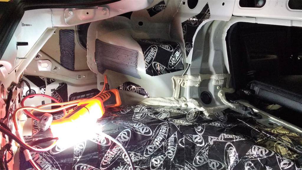
Easy stuff first. I deadened the trunk lid.
Before
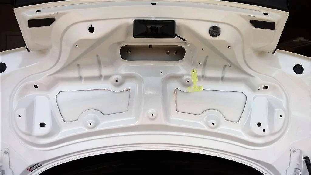
After (I used the scrap cutoffs inside the upper cavity, near the backup cam)

Next, I figured I'd build the amp rack. Board is 3/4" MDF, 24" from top to bottom and roughly 26" at it's widest point. I cut out my shape and laid out the components. There's a very good reason they are laid out this way. The amps all have their power inputs on the left side--the distro block is on the left side. The amps all have signal input in the middle--RCAs run up the middle (under the board). Speaker outs will run straight down the middle, under the board. I've never had an issue having speaker outputs cross over RCA inputs, but have definitely had issues when RCA inputs come anywhere near power inputs. Except for the speaker outputs crossing the RCAs at right angles, all power/signal/output wires will be separated as far from each other as possible.
Traced around all the components and marked for drilling holes. That countersunk center hole is where the board mounts to the spare tire mount. Take the time to do this step right. Note I double-marked the component mounting holes with a black marker for emphasis. Mark all your drill points clearly...write little notes if you have to, it'll all be covered later. Nothing is worse than getting to this point and screwing it up by drilling the wrong size holes or off-center holes.
Drilled the holes for wiring, including countersunk holes for threaded inserts and rounded over the wiring holes with a 1/4" roundover bit.
A bit out of order here, but the amp rack has feet. It sits flat on the spare well floor, about a 1/4" above the spare mounting bracket. Feet are 1-1/8" dowel rod from Home Depot. All feet are exactly 2" long.
Next up was painting the board. 8 or 9 coats of Krylon Gloss White and two coats of Rustoleum Gloss Clearcoat later. The threaded inserts are also installed here.

Mounted all the components and wired up the DSP to Amps signal wires. Everything but the distro block is sitting on 1/4" spacers I sprayed black (in the little box here).


Space under amps and TWK-88 for cooling.
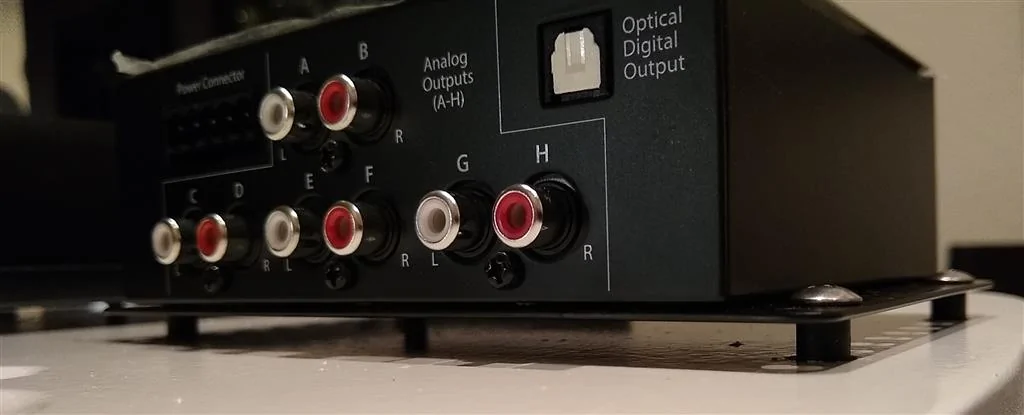
Underside. At the top center, you'll see the RCAs go into Y-splitters. That's b/c I'm bridging two channels on the 600/6 for the midbasses. JL tech support told me that when bridging, you need to supply input to both the L/R inputs of each channel. So here I created "two lefts and two rights" with 2 Y-splitters. Signal (except for the input from HU) is done, and Power will be done before installing the rack into the trunk.

Using peel and stick zip tie bases with a screw driven in. Been using this cable management method for years and never had one move.
0-gauge body ground upgrade. Not exactly a "Big 3" but sure is an upgrade to the 6-gauge-looking factory ground underneath the shock tower terminal! In the last pic, you can see I sanded off the paint to ensure a better ground. I have since coated the exposed metal with clear nail polish. My wife will never know she contributed to this build...

So that's where we are right now. Still a lot of work to do. Thanks for joining me on this adventure!
Sponsored
Last edited:

 so I had to move them out of the way. Turned out well, I think. That mess on the right-hand side is all the power wires; +/-/turn-on are all here and go nowhere near any RCAs.


 Having never run wires down the driver's side before, I didn't want to assume I'd have room for that big of a bundle, so I broke it down into two bundles that I can run in different paths if need be.


")