Deleted member 69311
Guest
- Thread starter
- #1
This is a step by step tutorial on how to wire up your active exhaust.
Car: 2018 Mustang GT base model - No active exhaust
Installing: 2018 GT350 exhaust // GT350 Mufflers
Actuators: 3-pin kuster actuators
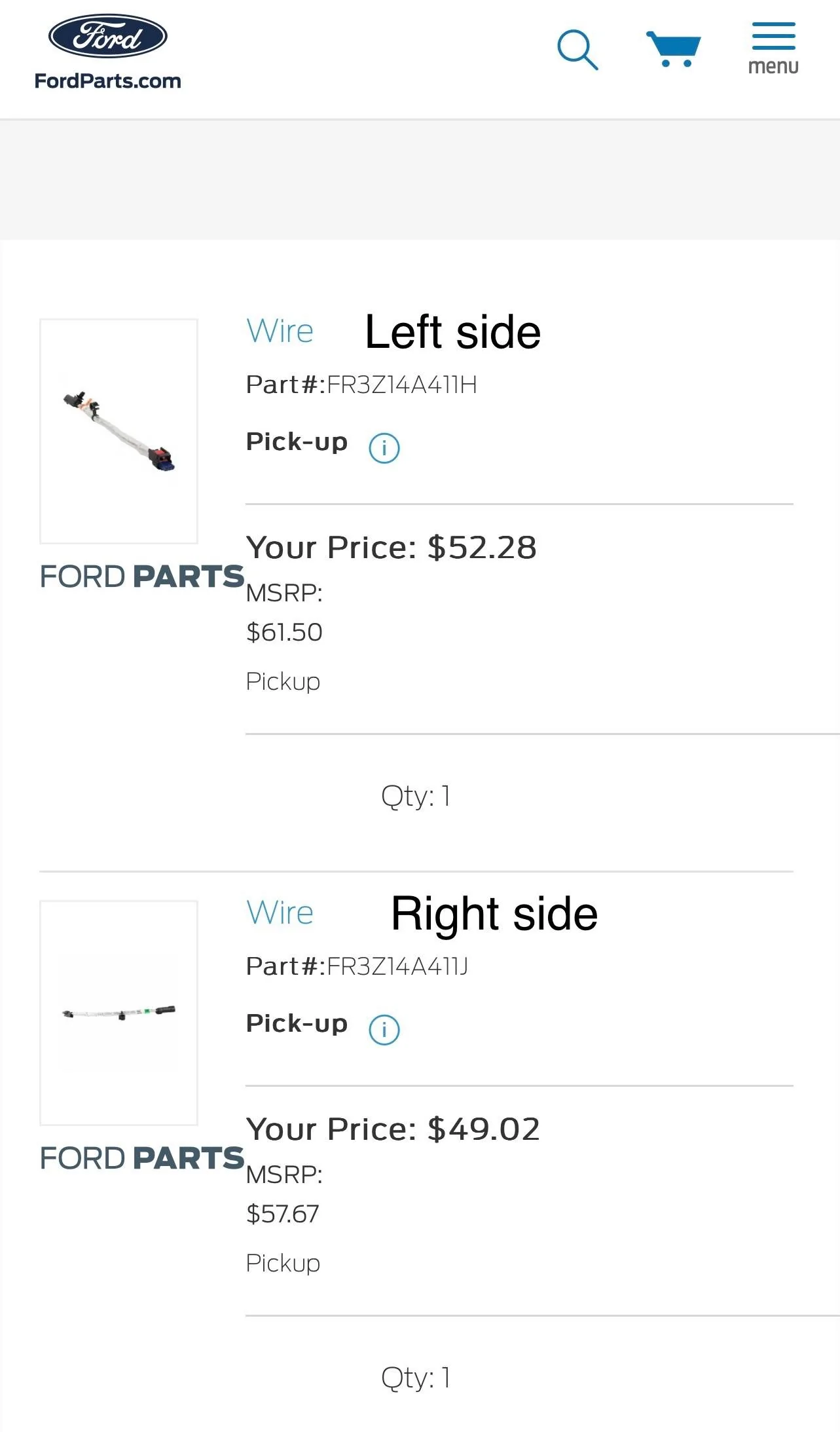
Parts to order:
FordParts.com:
Left jumper Part #: FR3Z14A417H
https://parts.ford.com/shop/en/us/wire-assy-6539401-1?pdp=y
Right jumper Part #: FR3Z14A411J
https://parts.ford.com/shop/en/us/wire-assy-6582847-1?pdp=y

Amazon:
Latching switch: https://a.co/d/a32LUJu
40ft 18awg wire : https://a.co/d/6oUgObo
Fuse holder: https://a.co/d/8yQrENC
Heat shrink: https://a.co/d/gYirUsp
Wire connectors: https://a.co/d/bFsRqdl
Wire sleeves: https://a.co/d/16t8ctd
Wire loom: https://a.co/d/aM8e5vz
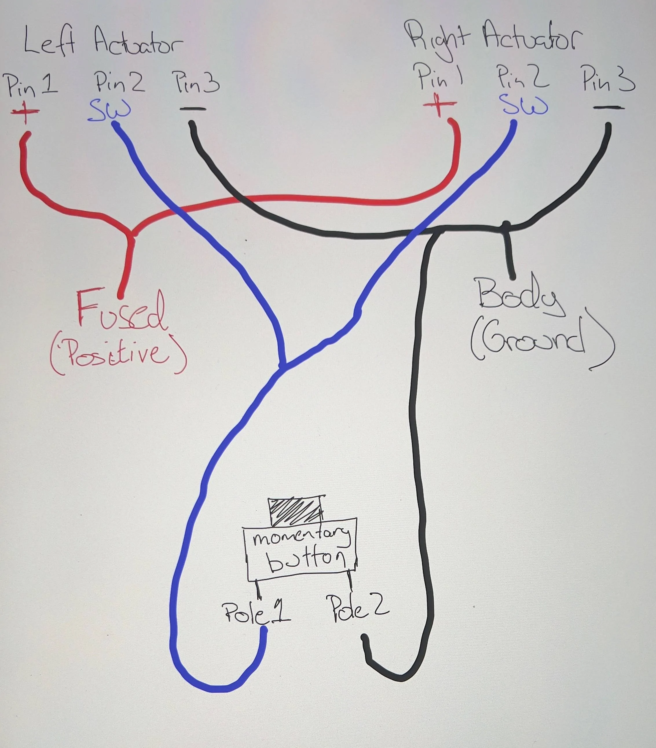
Wiring diagrams:
#1 : Positive Wires - Get direct power
#2 : Switch Wires - Negative switched
#3 : Negative Wires - Go to constant ground of car.
Wiring explained:
Huge thank you to @MrBD1348 for drawing the wiring diagram. Because of him I was able to make it work!


Step 1: Mark your Left and Right harness. Cut off the big connector on both jumper cables. Then pull wires out of the harness.

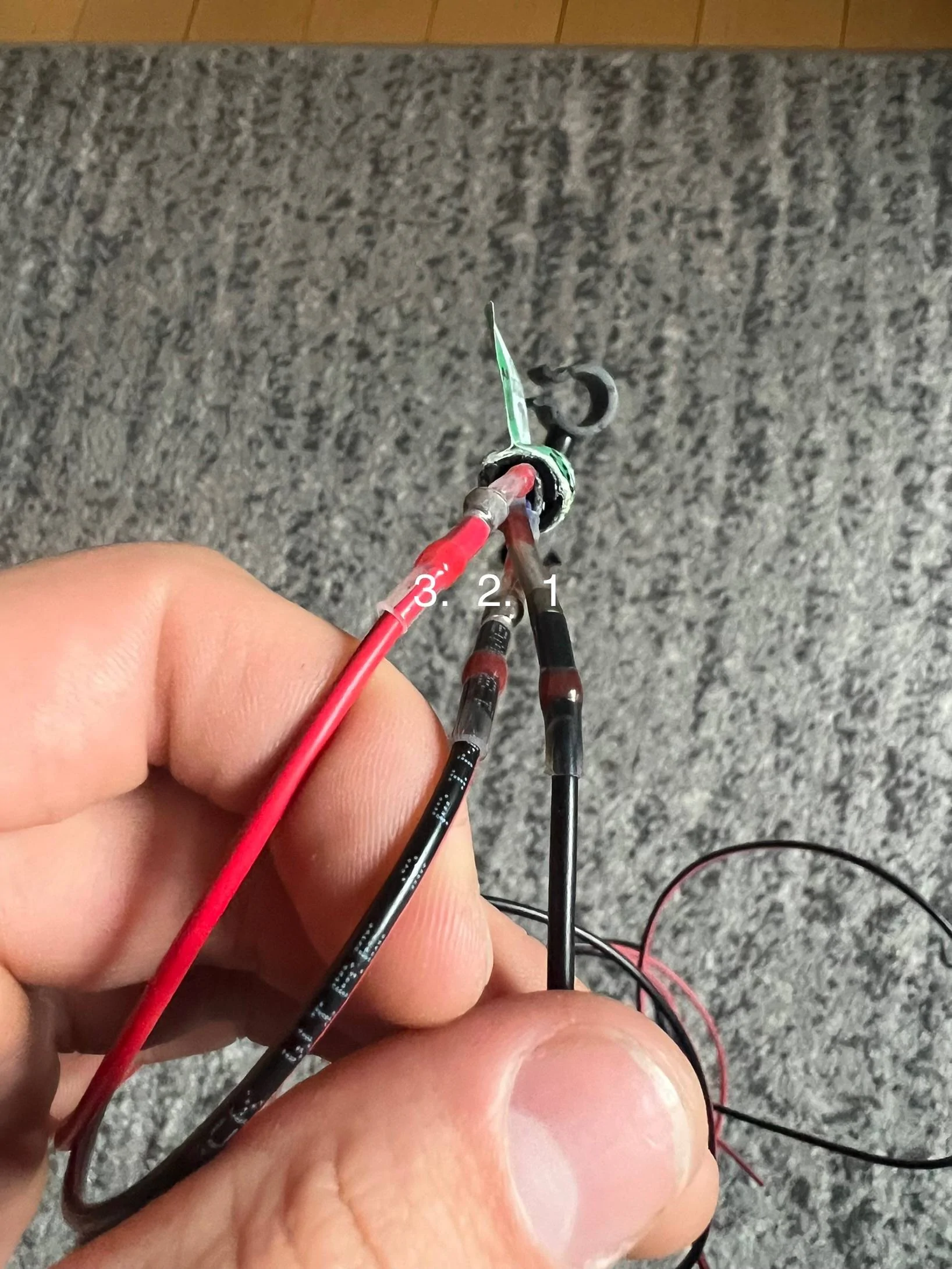
Step 2: Find and label each wire. Starting from right to left (red clip facing up), the wires are 1. 2. 3.
Step 4: To give yourself more wire to work with, cut off about 3 feet of wire and connect (with the wire connectors, and heat shrink over it) to each of the ends of the connector wires. Add more RED wire to wire #3, and more black wire to wire #1, and another black wire to wire #2.

(MAKE SURE TO LABEL WHICH WIRE IS WHICH IF USING THE SAME COLOR WIRE FOR MULTIPLE WIRES)
Step 5: Once you have extra wires to work with, connect both #3 RED wires together, and #1 BLACK wires together, and #2 BLACK wires together.
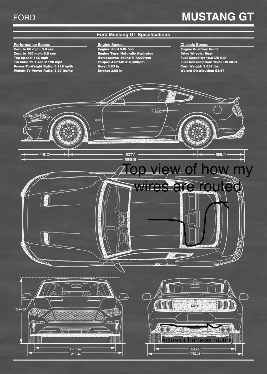
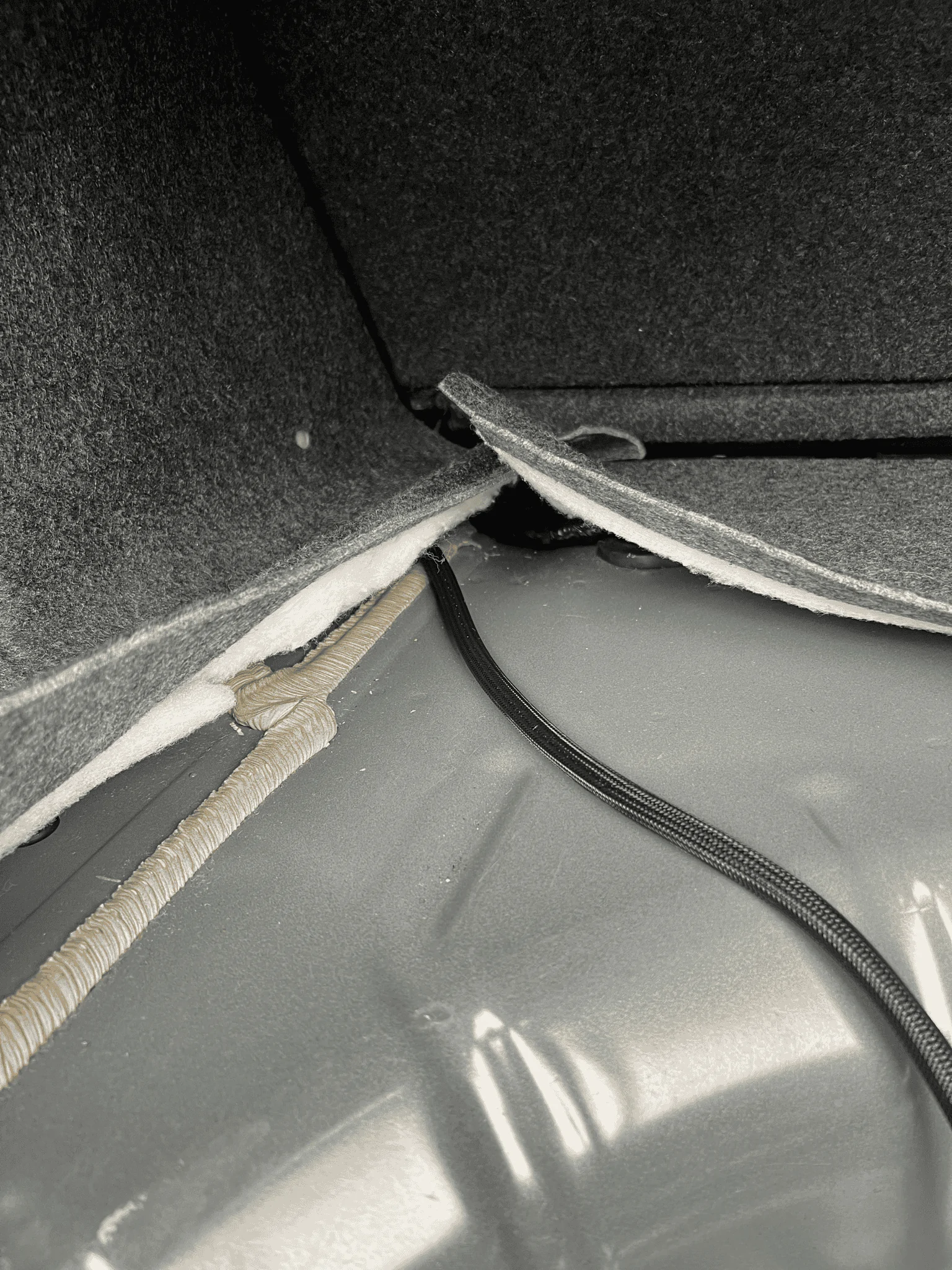
Step 6: Put down back seats and measure enough wire from the back, to the center console, or how ever much you need with how you’ll route your wires. Add a foot or 2 for extra play room just in case (you can cut and adjust it later) and cut your measured wires. You’ll need a total of 3 wires running to the center console. I ran my wires under the back seats, and shoved it under the carpet of center console, leading it into the center console. Make sure to shove your wires on the side of the carpet so when you reinstall the center console, it doesn’t pinch the wiring.

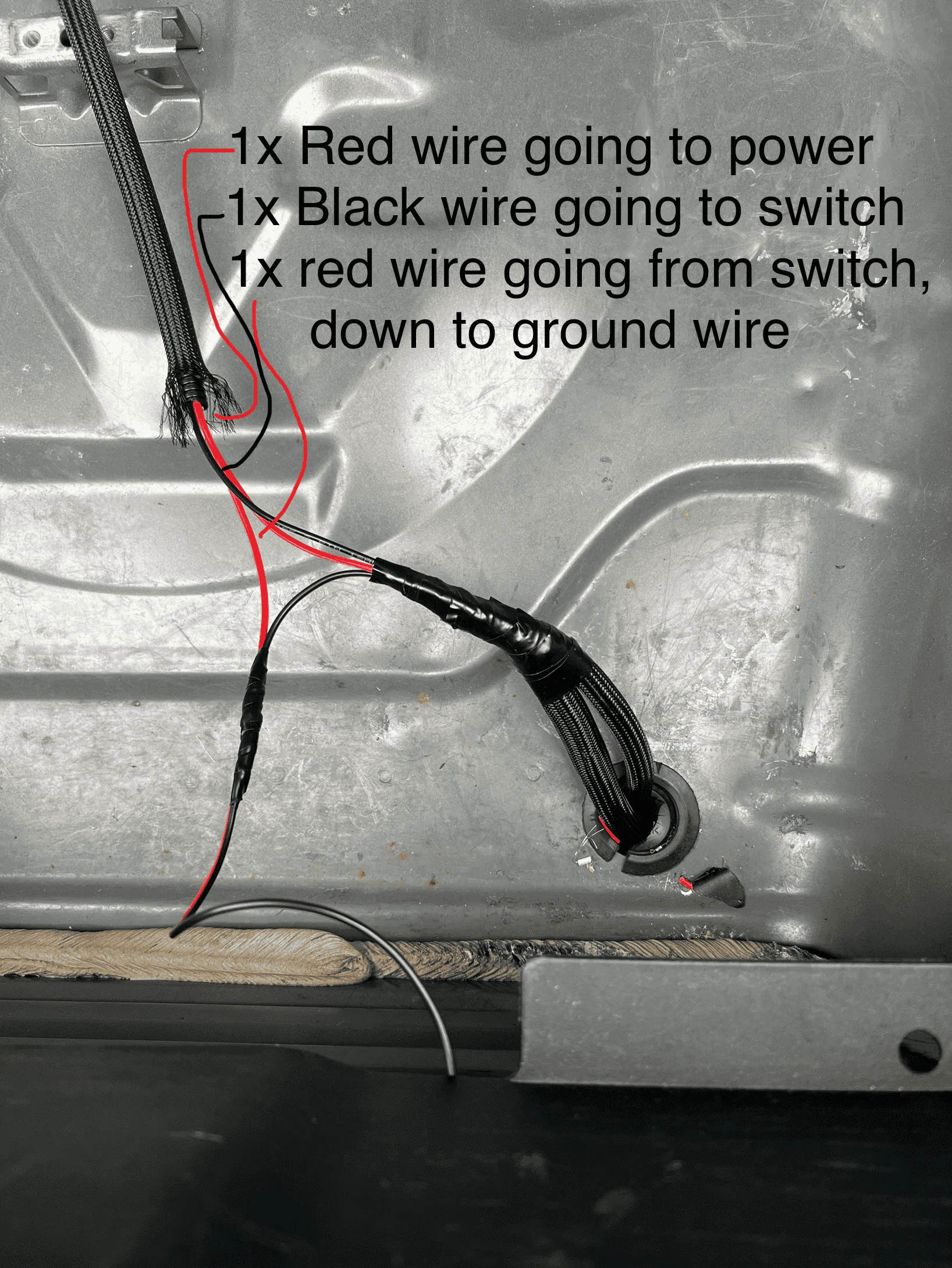
You will need 1 RED wire at center console (that will be power) and 2 other wires to connect to the switch. One going from the back of the car, to the switch, and another wire going from the switch, back to the car.
Step 7: (trunk area) Take your #1 Negative wire and ground it somewhere to the metal. (If you remove your black plastic trunk panel, there should be a ground screw next to the trunk latch)
Step 8: Take the long RED wire and connect it to your #3 RED positive wires. Now take your other long wires (red/black still attached together) and attach the BLACK wire to your #2 switch wires. Then take the RED wire and tap into your ground wire.
To recap: You should have a total of 3 wires attached and running to your center console.
RED positive wire connected to #3 RED wires,
BLACK wire attached to your #2 Switch wires,
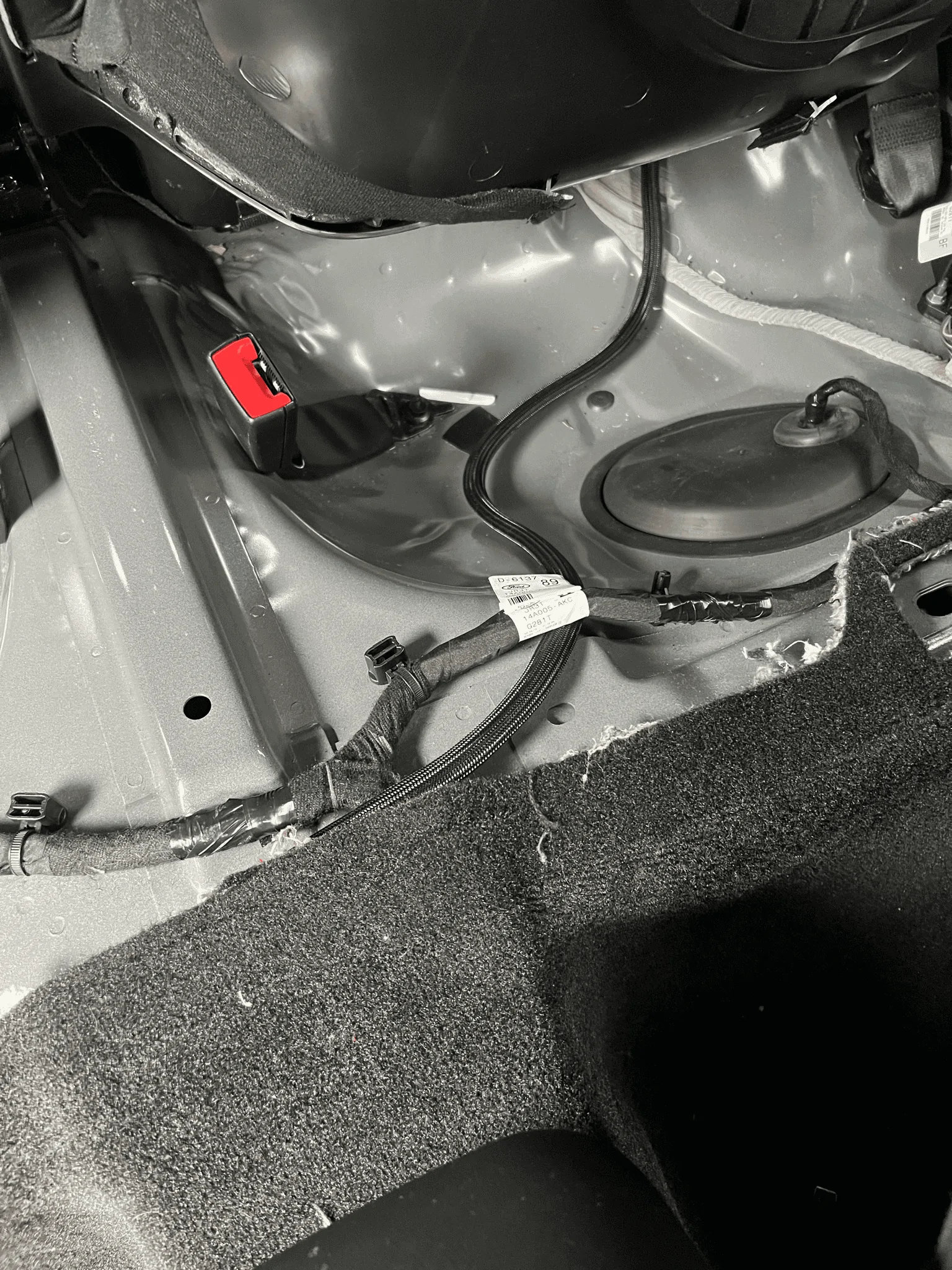
RED wire that’s spliced into ground wire that’s coming from your #1 wires. Where your spare tire is, there should be a rubber grommet plug on the right side. You can take it out and make a hole in it. Feed your connectors through that hole and plug them into the actuators.
From under the car: They split left and right

Now onto the center console:
Step 9: Pop off your center console and disconnect key detection connector. (If you don’t know how to, find it on YouTube)
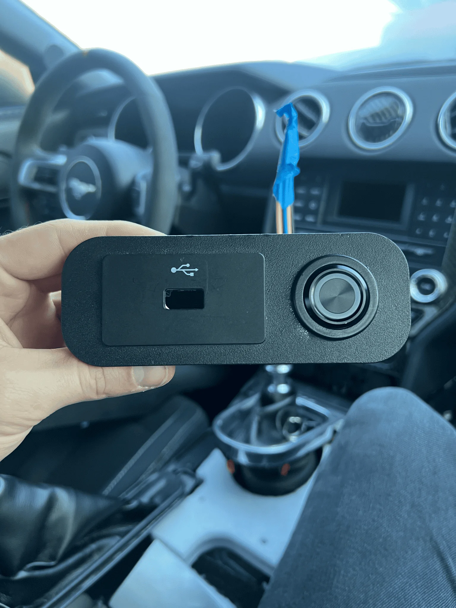
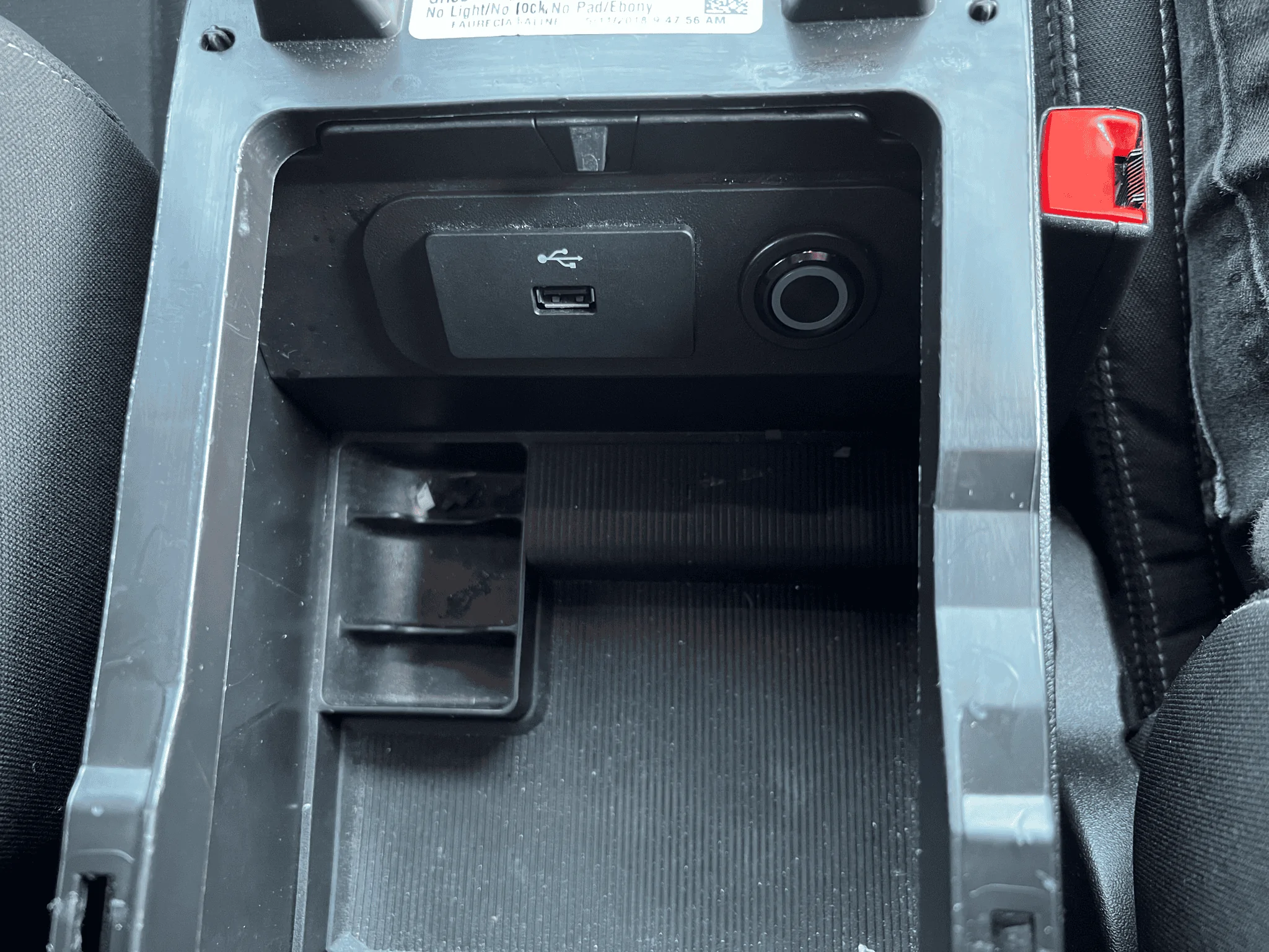
Step 10: Pop off the USB panel and disconnect USB and Power outlet
Step 11: Take power outlet out of its socket, but leave the housing in. (Black plastic top ring)
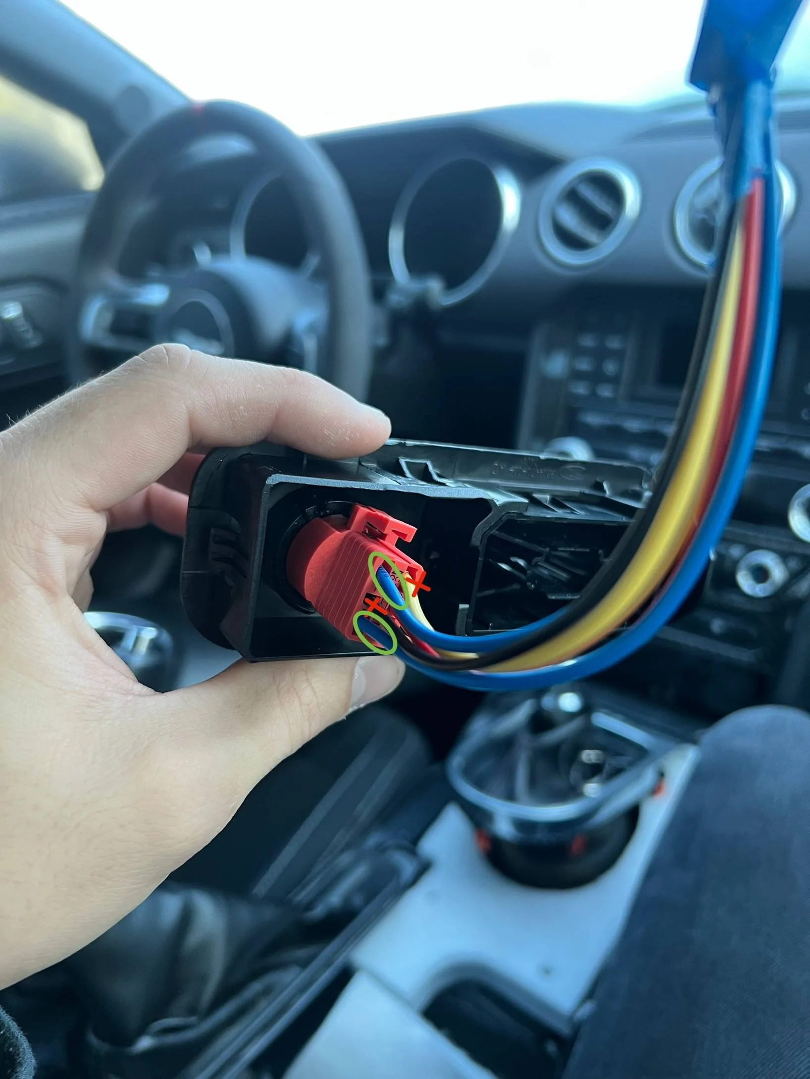
Step 12: Take your switch and unplug it from its connector. Carefully pull out both yellow wires and the black and red wires. Keep both blue wires. (If you want the LED light to work, don’t pull out the red wire)
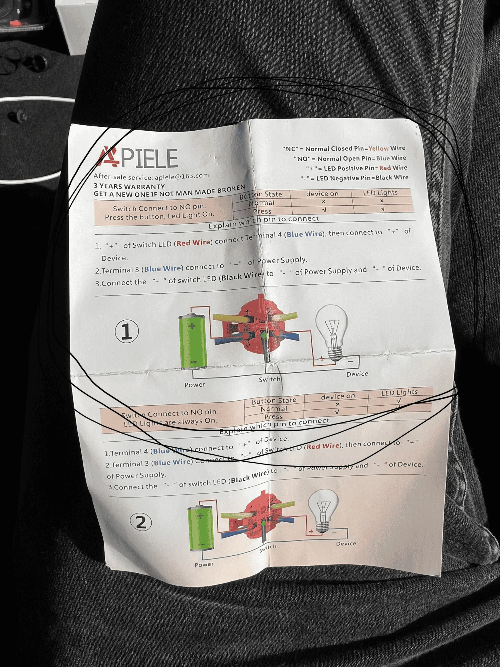
Switch wiring diagram if you need it #1
Step 13: Push the switch into the power outlet housing. (When you take out the housing, you have to first clip the housing back in - black circle - then slide your switch into it. (If you need to take the switch back out, you have to tap it out of the socket. Be careful so you don’t break anything.)
Step 14: Plug the switches connector in from the back.
Step 15: Take your 2 connected black/red wires and connect the BLACK wire to the bottom left blue wire (#3 on diagram.) Take the RED wire and connect it to the bottom right blue wire (#4 on diagram)
** if you want your LED light to work, connect the red wire with your bottom right blue wiring
Step 16: Take your Fuse holder and cut it the wires at the half way point.
Step 17: Connect one end of the fuse wire to your #3 red positive wire. On the other end of the fuse wire, strip back some wire.
Step 18: Take your power outlet port (the one still attached to the cars wiring harness) that you disconnected earlier and de-pin the positive wire (should be the darker wire)
Step 19: Once the wire has been de-pinned, take your fuse wire and insert it through one of the holes on the pin. (Make sure it’s not coming out of the side hole, that’s the hole that gets caught onto the latch of the housing)
Step 20: Reinsert the pin back into its place with the red wire. It should be a tight fit and you should hear or feel a click, letting you know it’s attached.
** Test to see if everything works. Press the button and listen if the actuators are turning. If not, check your ground or adjust your power connection.
If everything works, continue on.
Step 21: Wrap the whole thing in electrical tape.
Step 22: Put everything back in its place. Attach the USB plate back in its spot.
Step 23: start putting everything back. REMEMBER TO ATTACH THE KEY DETECTION CABLE BEFORE INSTALLING BACK THE TOP PIECE OF CENTER CONSOLE! Otherwise car won’t start.
That’s pretty much it. The button in pushed out position is OPEN VALVES, the button pushed in is CLOSED VALVES. I tried to reverse it to open when pushed in but couldn’t figure it out.
This won’t drain your battery because that charging port is on accessory mode. It turns off after 10min or so along with the rest of the electronics.
Honestly you can add your switch to any spot on the car. I just chose this spot because it looked clean. If you choose another spot, the wiring is still the same. You can still tap into the same power source and keep the power plug installed.
So this is a way to have your Active Exhaust on a switch. With this method you won’t be able to control your A/E through your dash. Only with the switch.
This is what I sounds like. It’s a warm start, valves opened. (Videos in attachments)
BBK LTH, BBK Catted Mid Pipe, 2018 GT350 exhaust w/x-pipe!
Car: 2018 Mustang GT base model - No active exhaust
Installing: 2018 GT350 exhaust // GT350 Mufflers
Actuators: 3-pin kuster actuators
Parts to order:
FordParts.com:
Left jumper Part #: FR3Z14A417H
https://parts.ford.com/shop/en/us/wire-assy-6539401-1?pdp=y
Right jumper Part #: FR3Z14A411J
https://parts.ford.com/shop/en/us/wire-assy-6582847-1?pdp=y
Amazon:
Latching switch: https://a.co/d/a32LUJu
40ft 18awg wire : https://a.co/d/6oUgObo
Fuse holder: https://a.co/d/8yQrENC
Heat shrink: https://a.co/d/gYirUsp
Wire connectors: https://a.co/d/bFsRqdl
Wire sleeves: https://a.co/d/16t8ctd
Wire loom: https://a.co/d/aM8e5vz
Wiring diagrams:
#1 : Positive Wires - Get direct power
#2 : Switch Wires - Negative switched
#3 : Negative Wires - Go to constant ground of car.
Wiring explained:
Huge thank you to @MrBD1348 for drawing the wiring diagram. Because of him I was able to make it work!
Step 1: Mark your Left and Right harness. Cut off the big connector on both jumper cables. Then pull wires out of the harness.
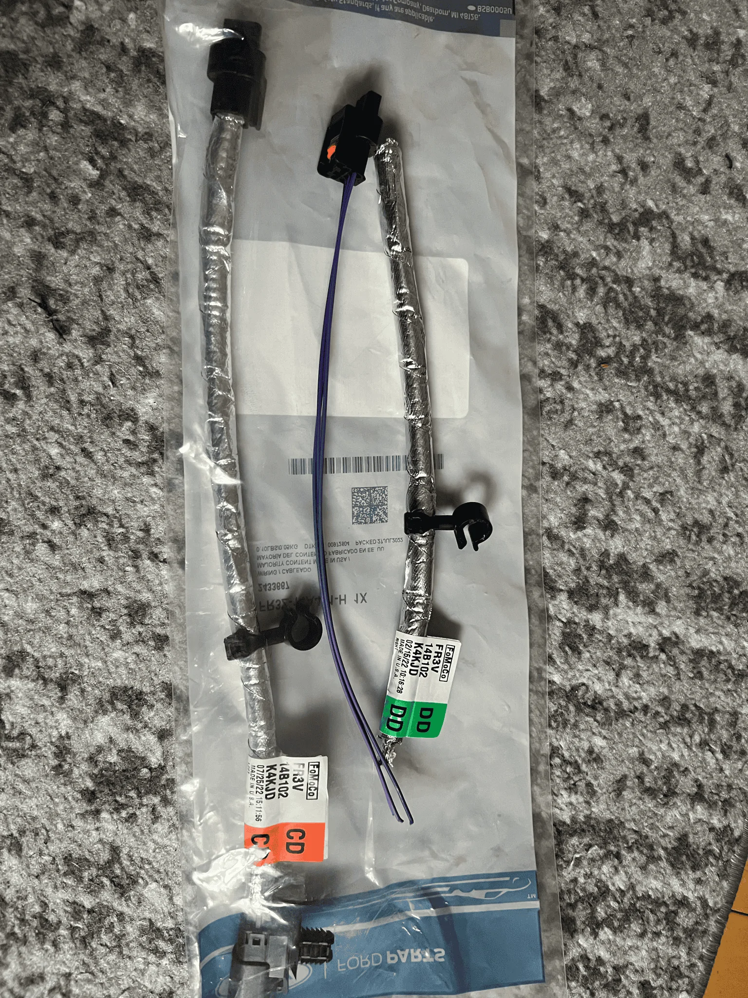
Step 2: Find and label each wire. Starting from right to left (red clip facing up), the wires are 1. 2. 3.
- 1: Negative wire
- 2: Switch wire
- 3: Positive wire
Step 4: To give yourself more wire to work with, cut off about 3 feet of wire and connect (with the wire connectors, and heat shrink over it) to each of the ends of the connector wires. Add more RED wire to wire #3, and more black wire to wire #1, and another black wire to wire #2.
(MAKE SURE TO LABEL WHICH WIRE IS WHICH IF USING THE SAME COLOR WIRE FOR MULTIPLE WIRES)
Step 5: Once you have extra wires to work with, connect both #3 RED wires together, and #1 BLACK wires together, and #2 BLACK wires together.
Step 6: Put down back seats and measure enough wire from the back, to the center console, or how ever much you need with how you’ll route your wires. Add a foot or 2 for extra play room just in case (you can cut and adjust it later) and cut your measured wires. You’ll need a total of 3 wires running to the center console. I ran my wires under the back seats, and shoved it under the carpet of center console, leading it into the center console. Make sure to shove your wires on the side of the carpet so when you reinstall the center console, it doesn’t pinch the wiring.
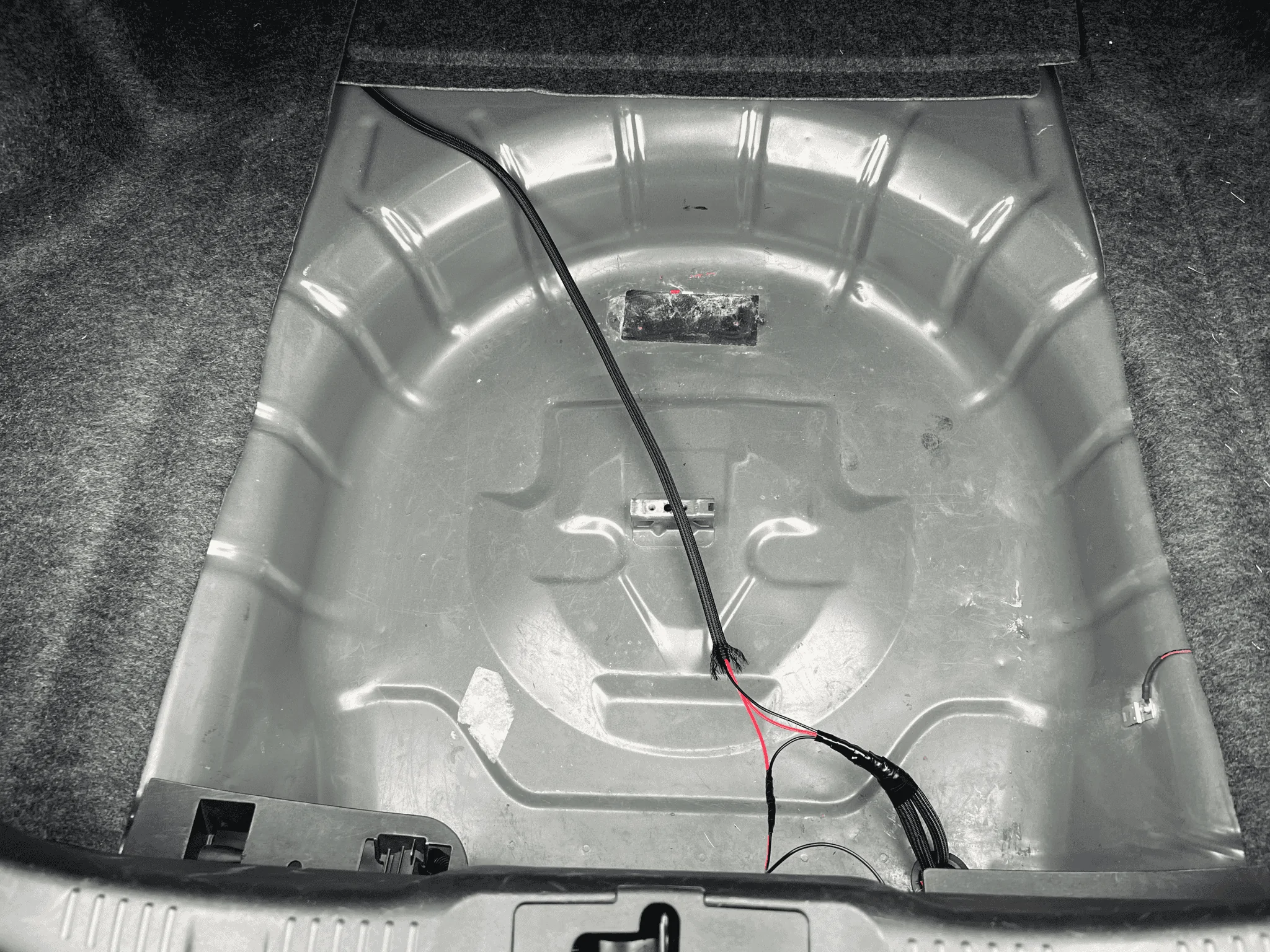

You will need 1 RED wire at center console (that will be power) and 2 other wires to connect to the switch. One going from the back of the car, to the switch, and another wire going from the switch, back to the car.
- Because the wiring you got from Amazon is attached together in a red/black pair, you don’t have to separate them. Just pull apart about 3inches on each end.
Step 7: (trunk area) Take your #1 Negative wire and ground it somewhere to the metal. (If you remove your black plastic trunk panel, there should be a ground screw next to the trunk latch)
Step 8: Take the long RED wire and connect it to your #3 RED positive wires. Now take your other long wires (red/black still attached together) and attach the BLACK wire to your #2 switch wires. Then take the RED wire and tap into your ground wire.
To recap: You should have a total of 3 wires attached and running to your center console.
RED positive wire connected to #3 RED wires,
BLACK wire attached to your #2 Switch wires,
RED wire that’s spliced into ground wire that’s coming from your #1 wires. Where your spare tire is, there should be a rubber grommet plug on the right side. You can take it out and make a hole in it. Feed your connectors through that hole and plug them into the actuators.
From under the car: They split left and right

Now onto the center console:
Step 9: Pop off your center console and disconnect key detection connector. (If you don’t know how to, find it on YouTube)
Step 10: Pop off the USB panel and disconnect USB and Power outlet
Step 11: Take power outlet out of its socket, but leave the housing in. (Black plastic top ring)
Step 12: Take your switch and unplug it from its connector. Carefully pull out both yellow wires and the black and red wires. Keep both blue wires. (If you want the LED light to work, don’t pull out the red wire)
Switch wiring diagram if you need it #1
Step 13: Push the switch into the power outlet housing. (When you take out the housing, you have to first clip the housing back in - black circle - then slide your switch into it. (If you need to take the switch back out, you have to tap it out of the socket. Be careful so you don’t break anything.)
Step 14: Plug the switches connector in from the back.
Step 15: Take your 2 connected black/red wires and connect the BLACK wire to the bottom left blue wire (#3 on diagram.) Take the RED wire and connect it to the bottom right blue wire (#4 on diagram)
** if you want your LED light to work, connect the red wire with your bottom right blue wiring
Step 16: Take your Fuse holder and cut it the wires at the half way point.
Step 17: Connect one end of the fuse wire to your #3 red positive wire. On the other end of the fuse wire, strip back some wire.
Step 18: Take your power outlet port (the one still attached to the cars wiring harness) that you disconnected earlier and de-pin the positive wire (should be the darker wire)
Step 19: Once the wire has been de-pinned, take your fuse wire and insert it through one of the holes on the pin. (Make sure it’s not coming out of the side hole, that’s the hole that gets caught onto the latch of the housing)
Step 20: Reinsert the pin back into its place with the red wire. It should be a tight fit and you should hear or feel a click, letting you know it’s attached.
** Test to see if everything works. Press the button and listen if the actuators are turning. If not, check your ground or adjust your power connection.
If everything works, continue on.
Step 21: Wrap the whole thing in electrical tape.
Step 22: Put everything back in its place. Attach the USB plate back in its spot.
Step 23: start putting everything back. REMEMBER TO ATTACH THE KEY DETECTION CABLE BEFORE INSTALLING BACK THE TOP PIECE OF CENTER CONSOLE! Otherwise car won’t start.
That’s pretty much it. The button in pushed out position is OPEN VALVES, the button pushed in is CLOSED VALVES. I tried to reverse it to open when pushed in but couldn’t figure it out.
This won’t drain your battery because that charging port is on accessory mode. It turns off after 10min or so along with the rest of the electronics.
Honestly you can add your switch to any spot on the car. I just chose this spot because it looked clean. If you choose another spot, the wiring is still the same. You can still tap into the same power source and keep the power plug installed.
So this is a way to have your Active Exhaust on a switch. With this method you won’t be able to control your A/E through your dash. Only with the switch.
This is what I sounds like. It’s a warm start, valves opened. (Videos in attachments)
BBK LTH, BBK Catted Mid Pipe, 2018 GT350 exhaust w/x-pipe!
Sponsored
Last edited by a moderator: