GTP
Deutsche Pony
- Joined
- May 27, 2015
- Threads
- 264
- Messages
- 6,057
- Reaction score
- 4,013
- Location
- Indy
- Website
- www.BambergAudio.com
- First Name
- Philip
- Vehicle(s)
- 2019 GT PP1 A10 Outrageous Orange HPDE mods
- Thread starter
- #1
Although I had on hand the Steeda Strut Tower Hole Saw, I instead decided to cut in a notch just sufficient to clear the strut shaft. This turned out to be more work than using the hole saw instead. But I like how it looks.
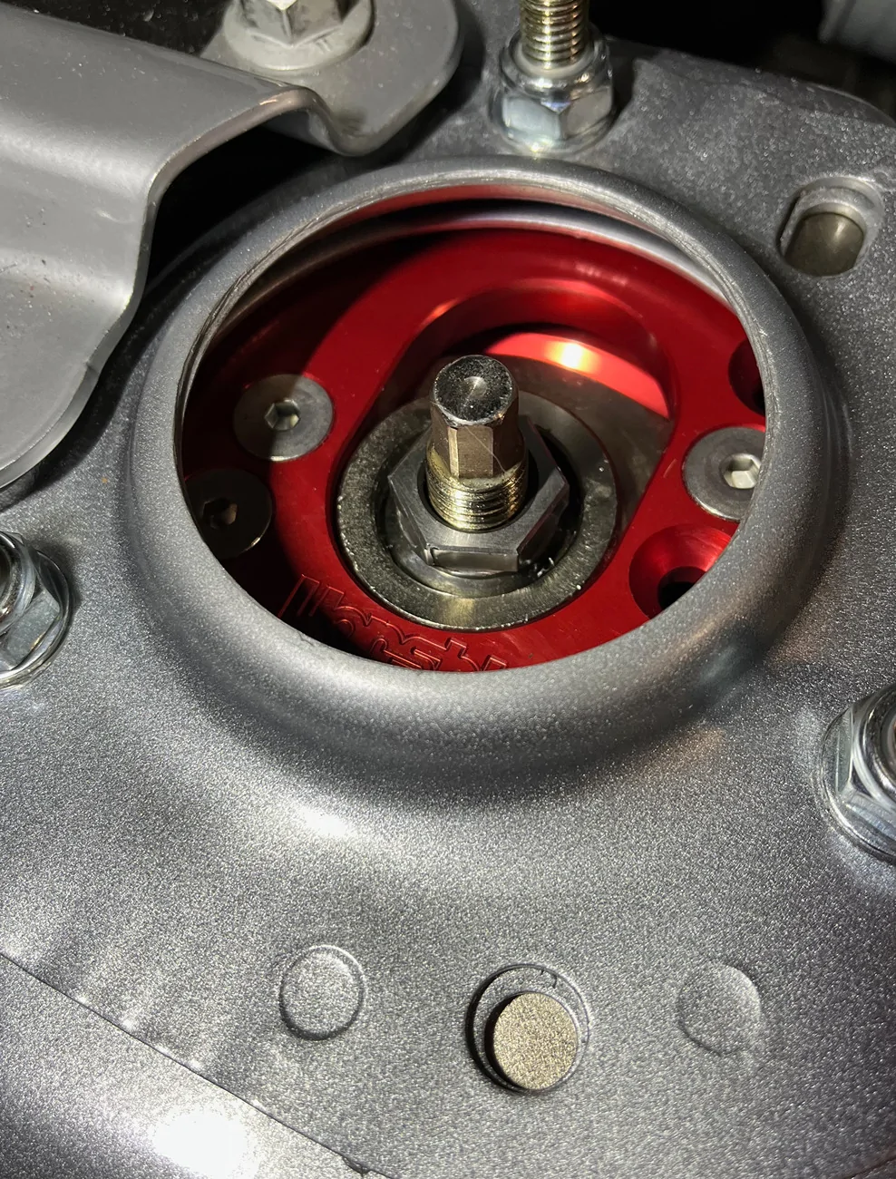
First check was with loose plates for any clearance issues under the shock tower. NPF

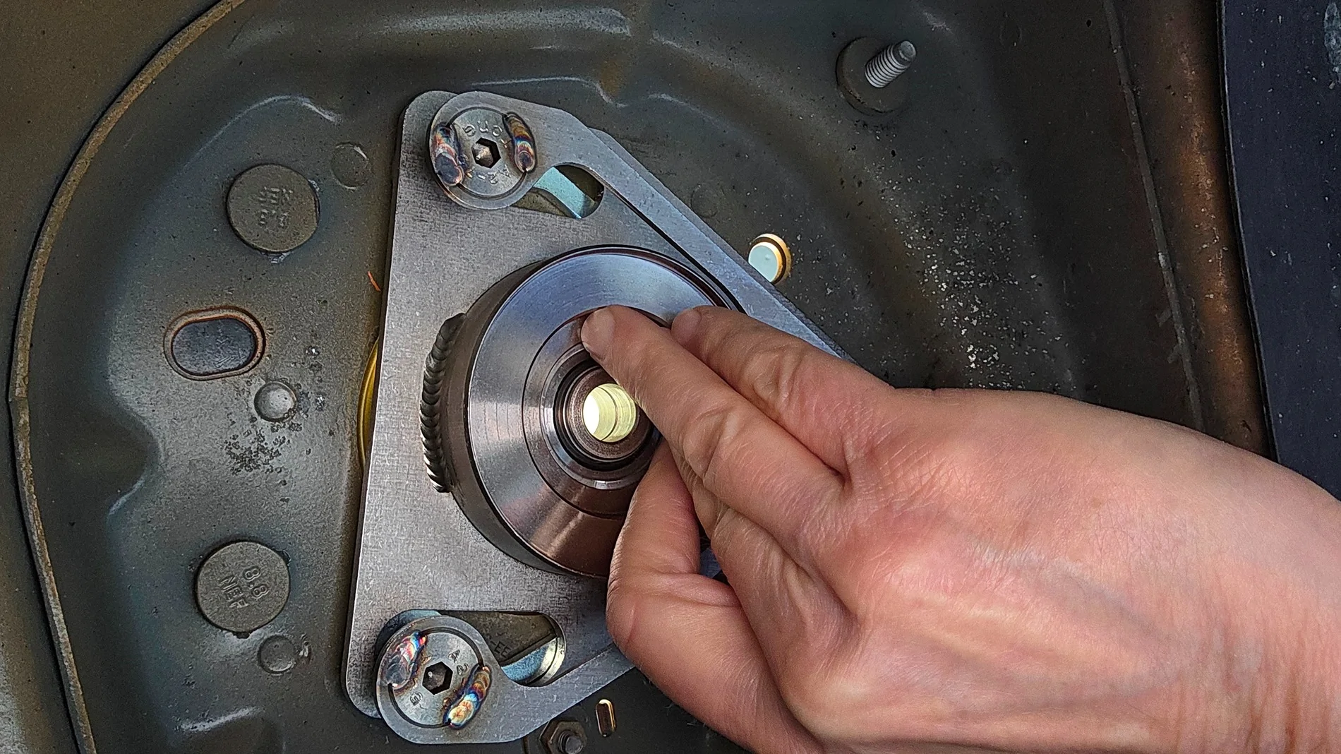
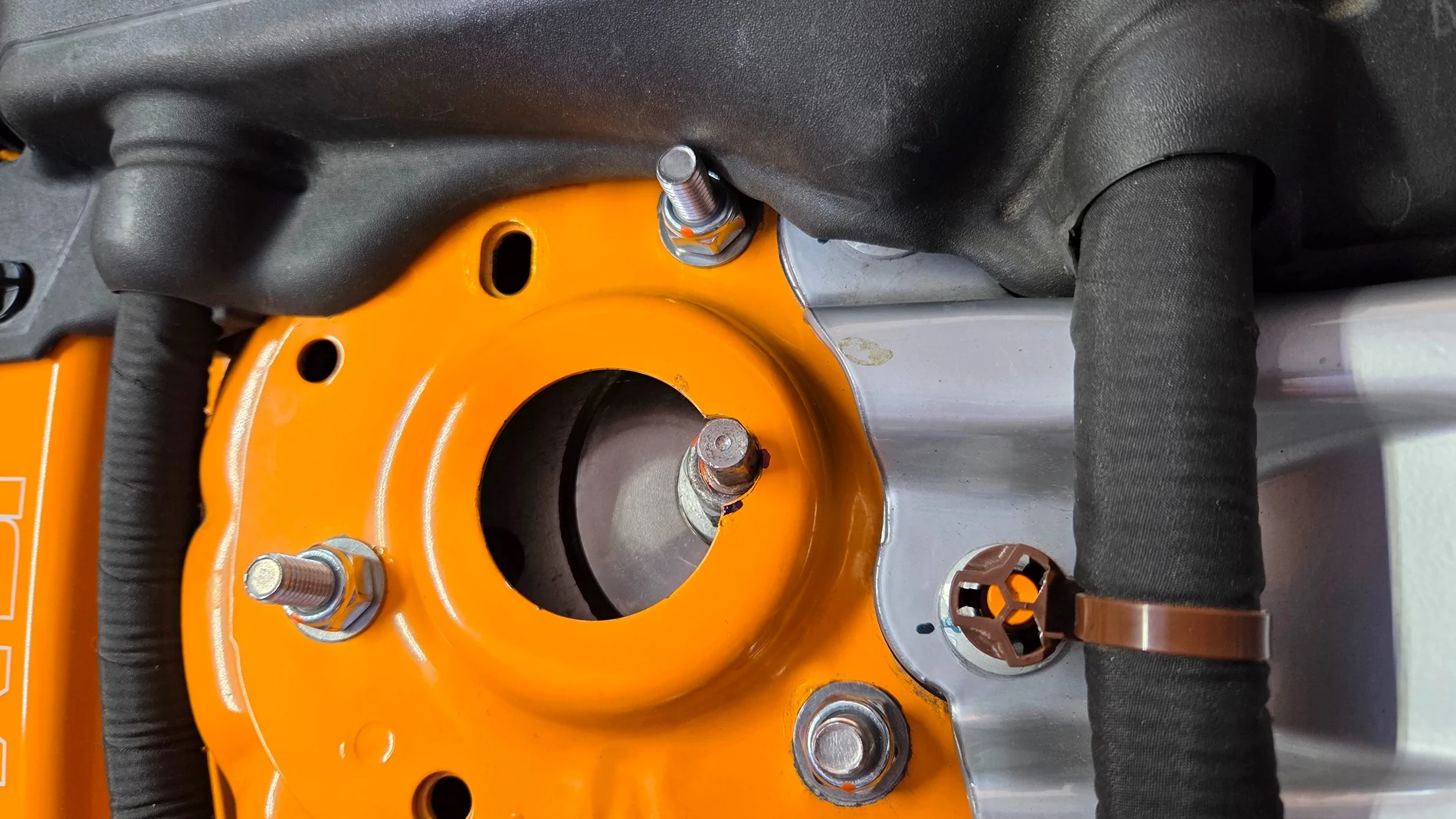
Mockup shown for loose, uninstalled camber plates. M14-2.0 bolt and nut purchased as aid to simulate the strut shaft and to locate center of the notch. M10-1.5 plain hex nuts used for convenience over Nyloc nuts.

Plate secured to tower, adjusted to positive camber limit. Note the bolt is a bit outboard of the hole center. I measured +0.6° camber from OEM (at tower hole center).

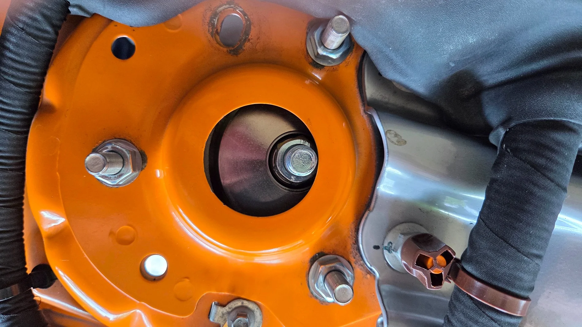
Plate adjusted to negative until bolt touches the tower hole.
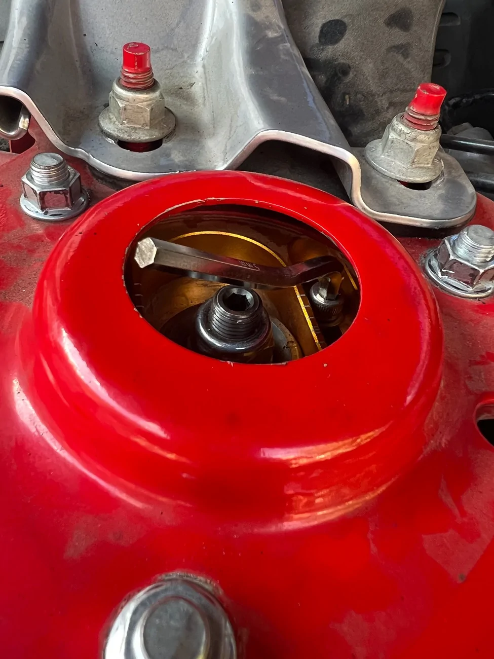
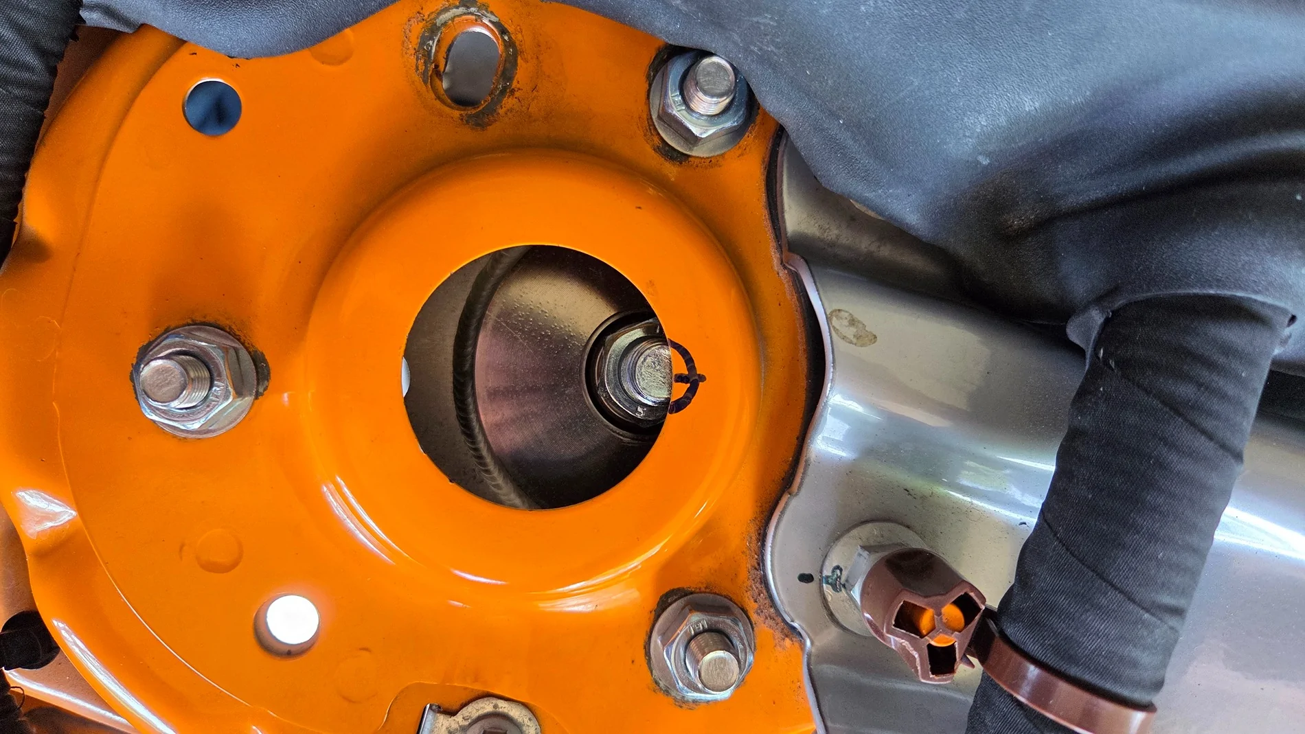
Marking profile of notch.
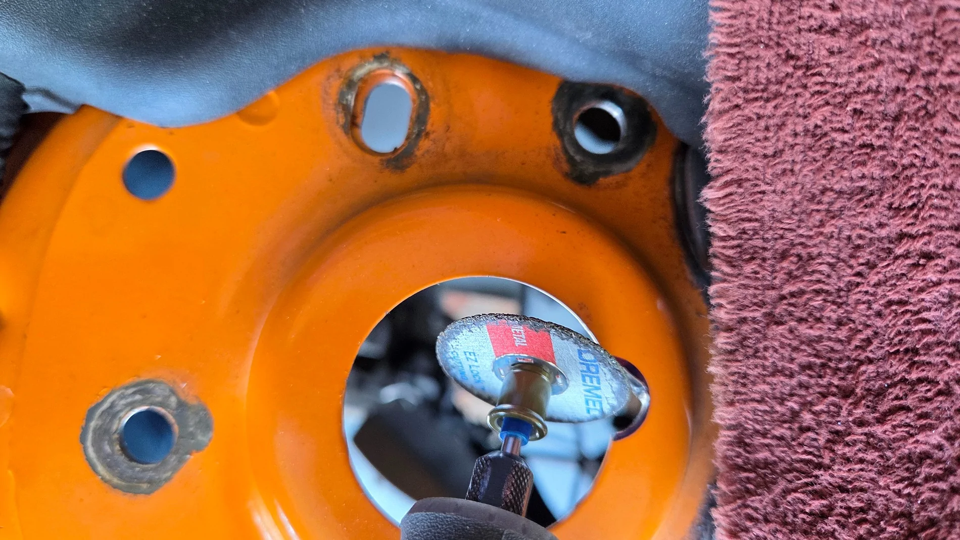
Using Dremel cutoff wheel to remove some of the notch.
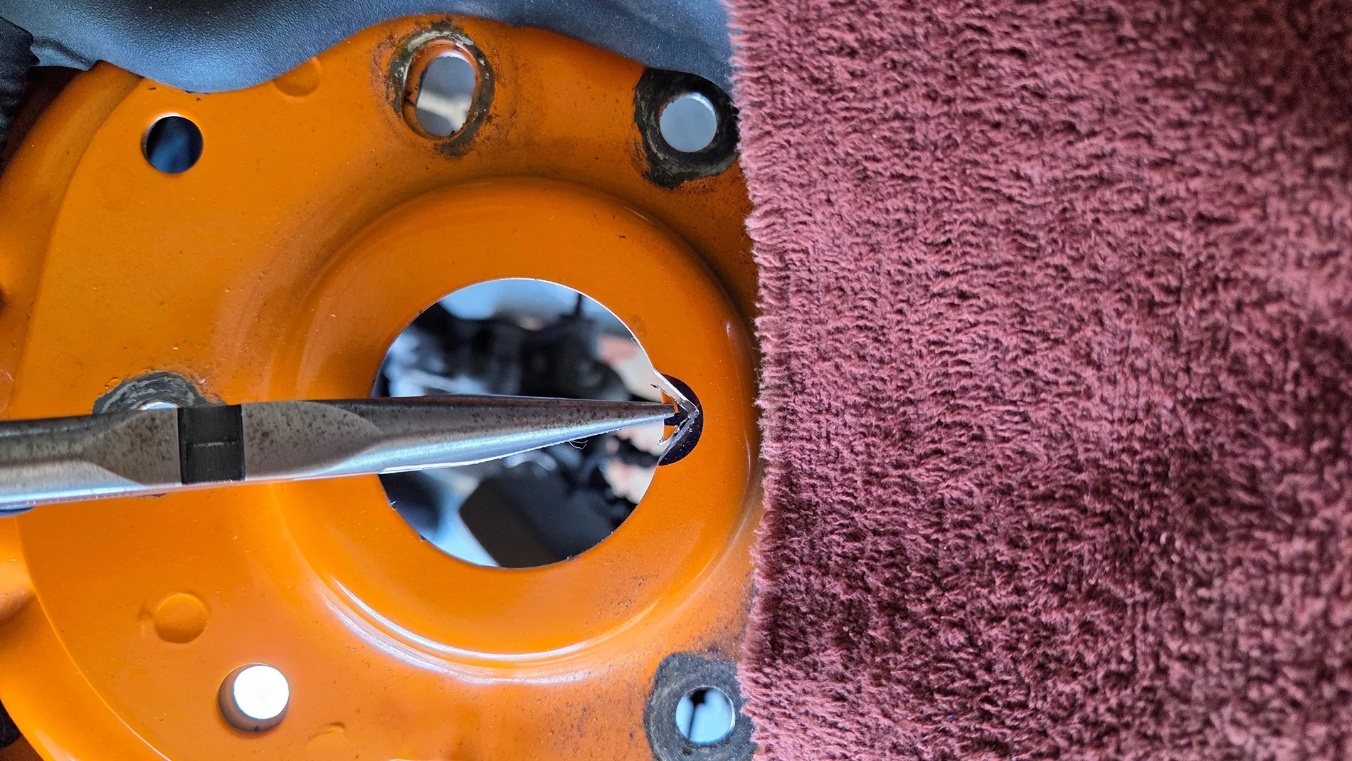
Breaking out the little triangle piece.
Holding the Dremel tool cutoff wheel at an angle to effectively remove more material and with a round profile.
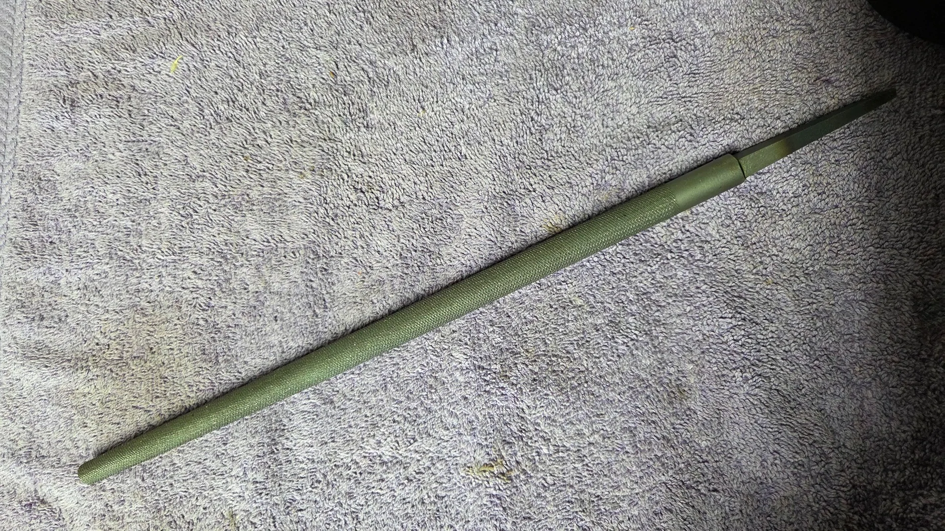
5/8” round file for smoothing out the notch.
All seems well with this result.
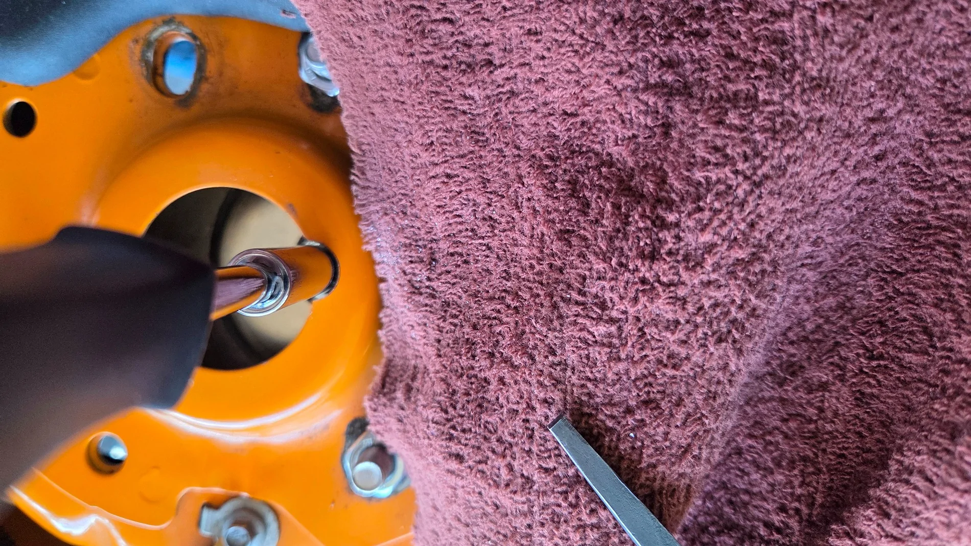
I use a 10mm deep socket on a nutdriver handle to change camber. This photo shows that the notch clears the nutdriver. However, the car is jacked up and the wheels straight ahead.
Once the car is lowered and steering operated lock-to-lock, I discovered that the strut shaft wanders around a larger area than was provided by this initial notch size.
Ultimately, I had to re-mark with the car on the ground and steering operated lock-to-lock to determine a slightly different notch center and size. Much more filing and checking ensued. This is when I reconsidered the option of the hole saw.
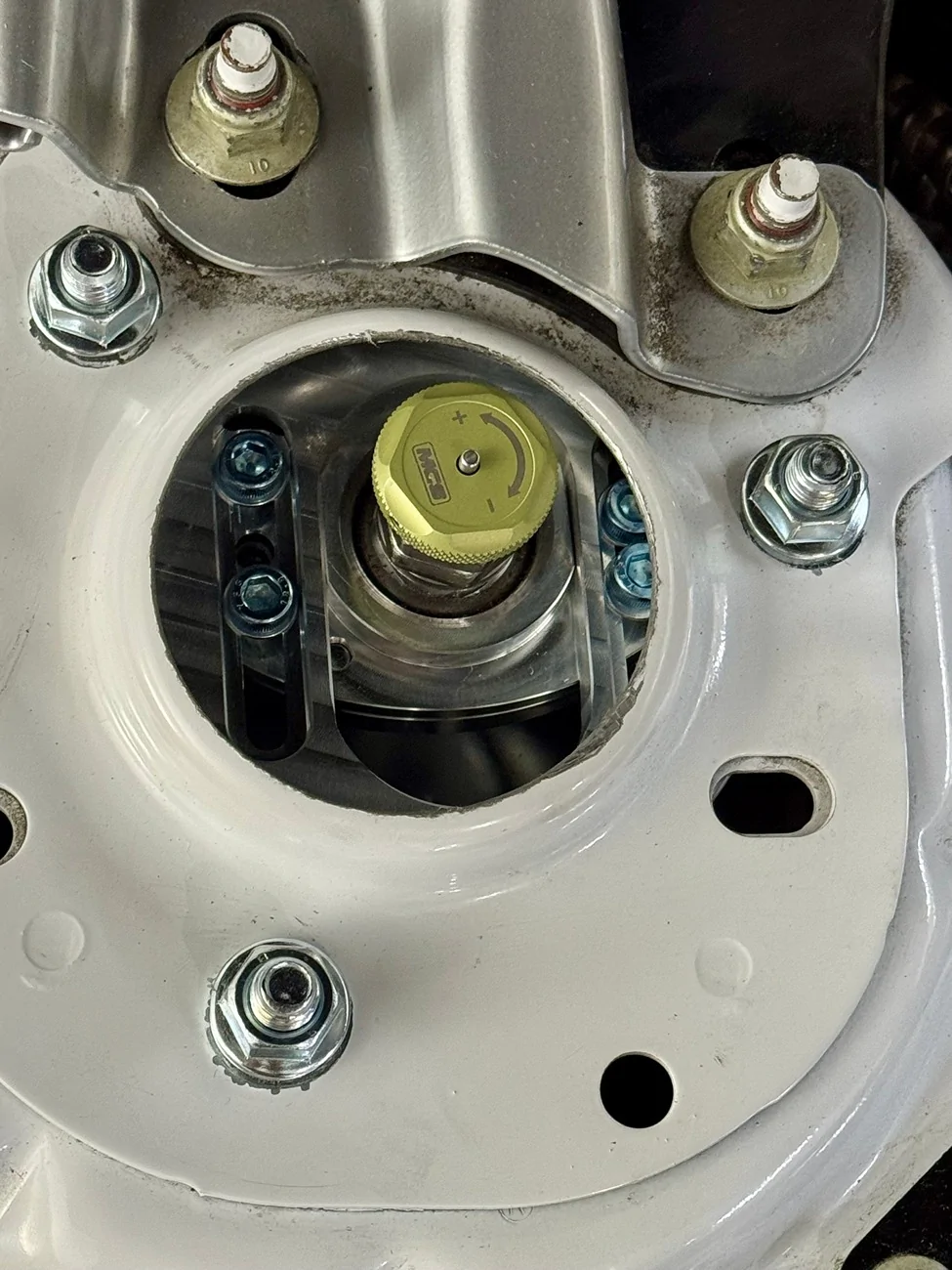
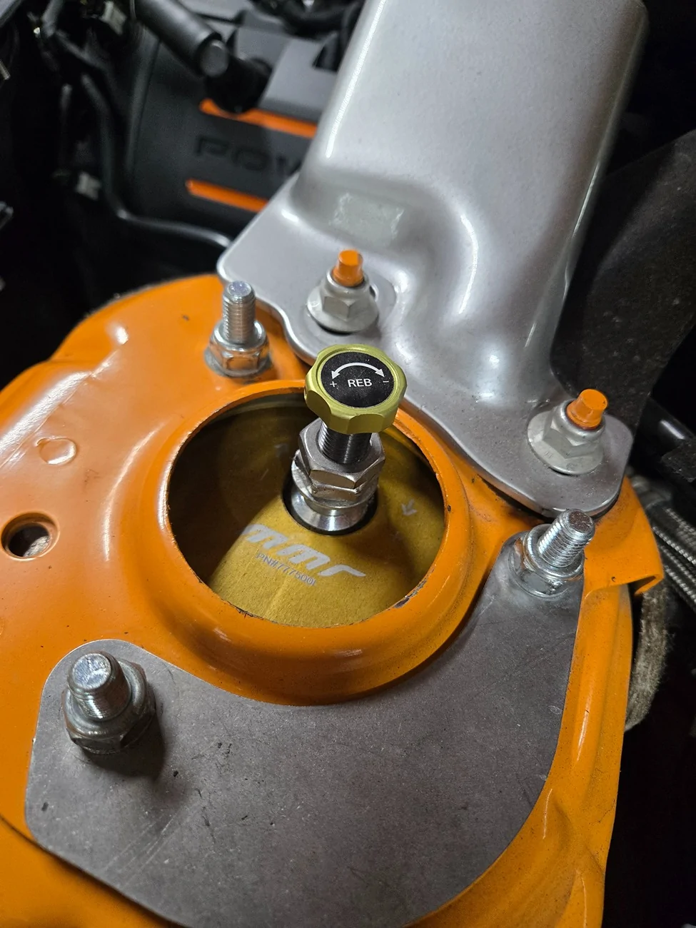
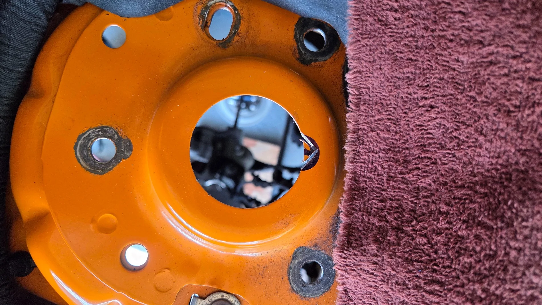
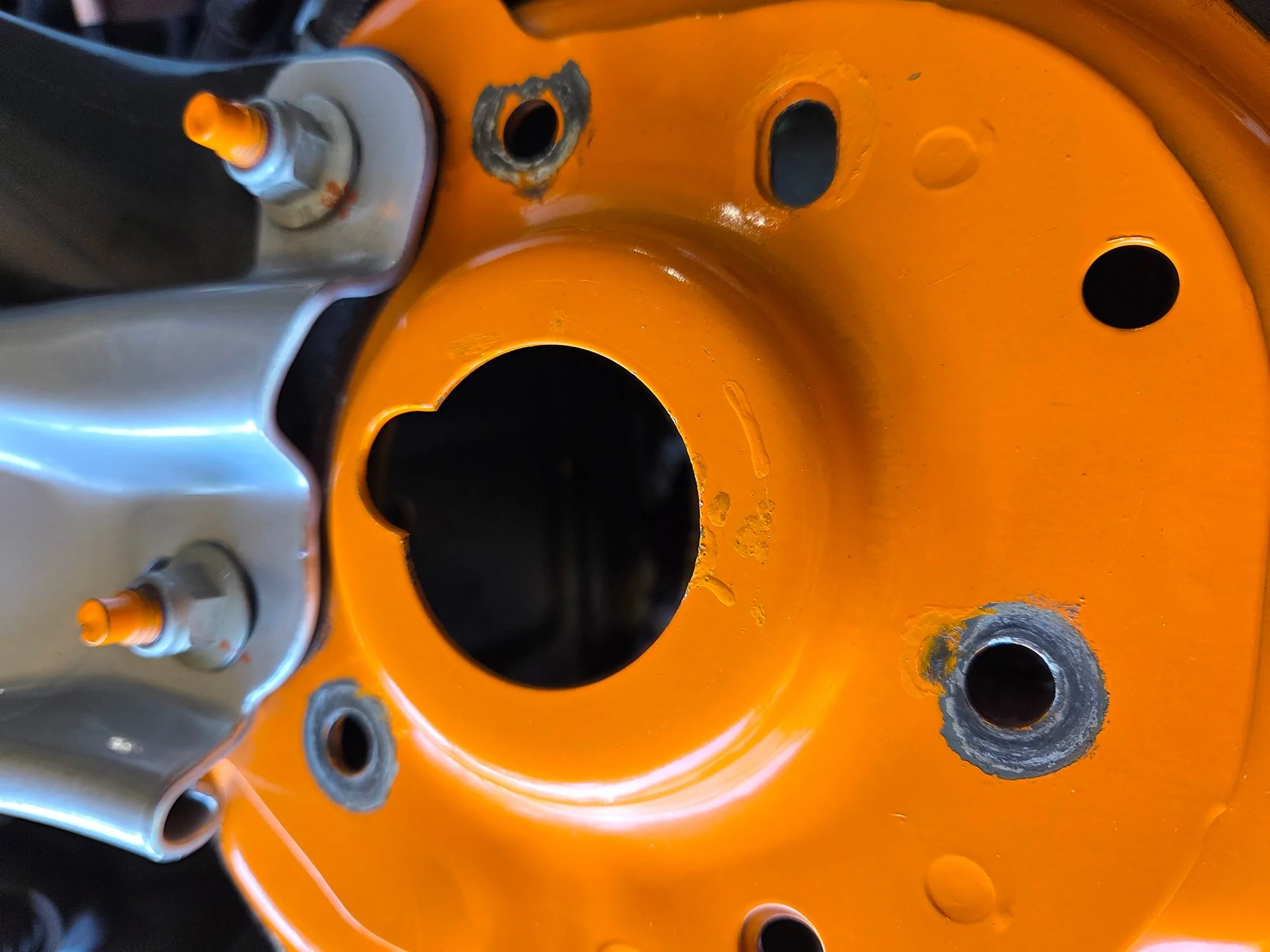
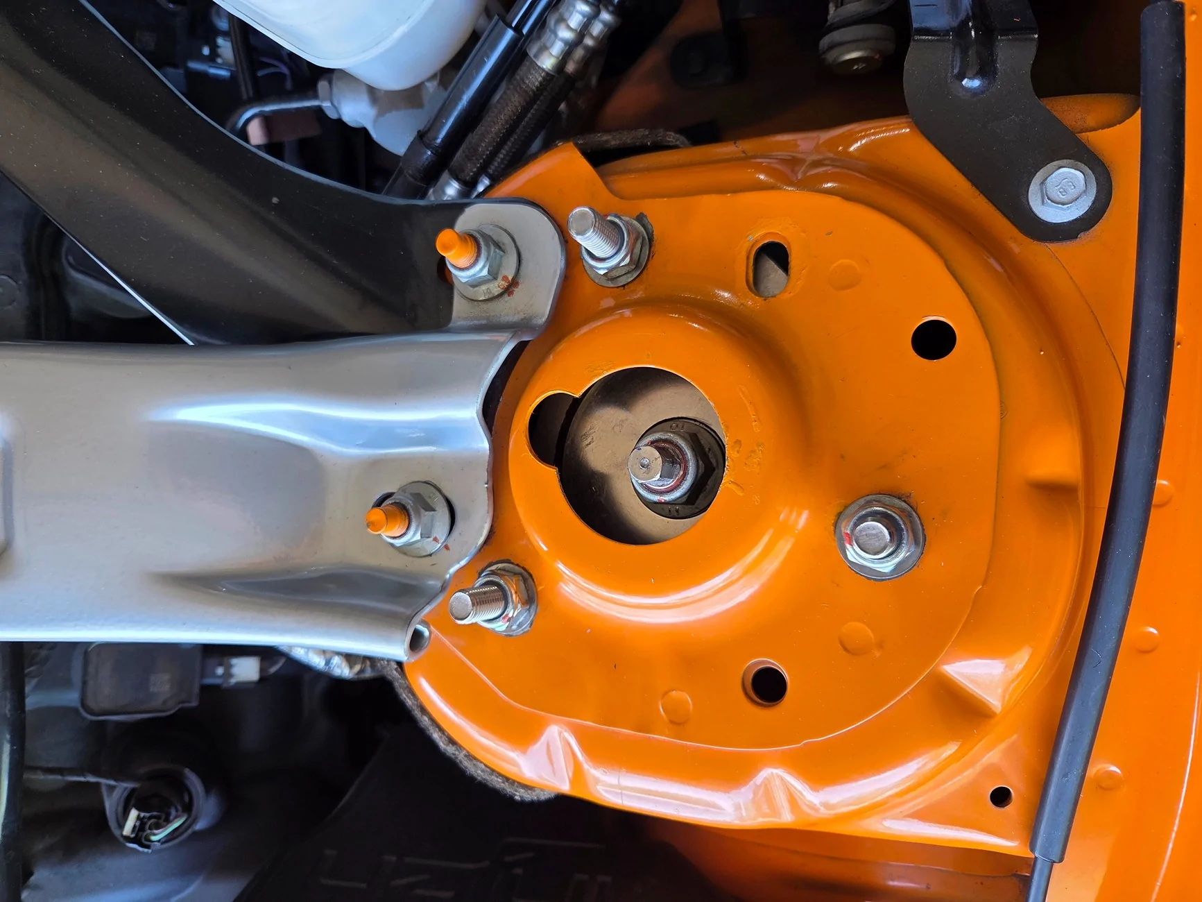
Final result: smooth and painted notch, properly located and sized. <2 photos>
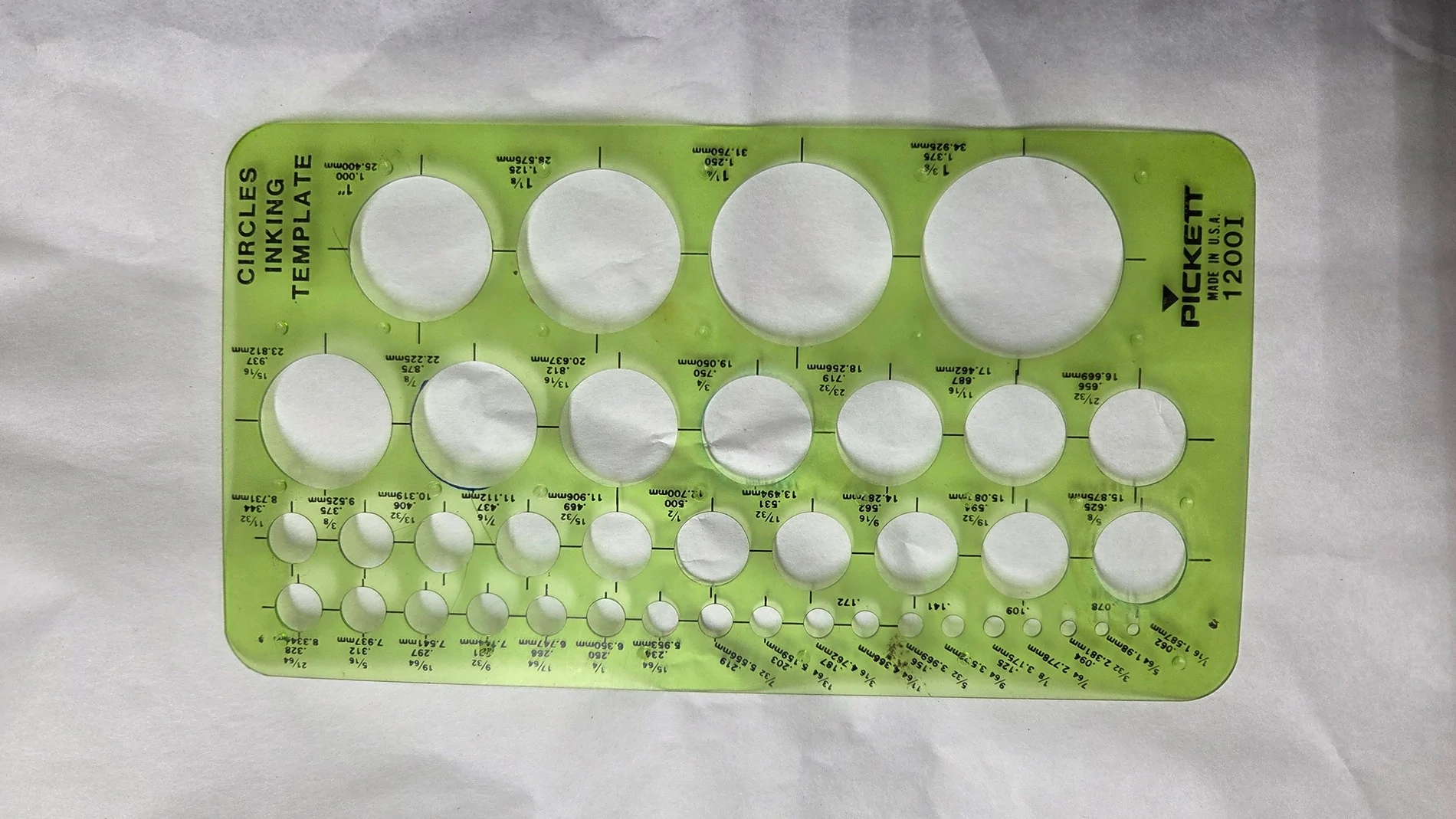
Old drawing circle template helped with marking. <photo >
Up next: Additional information unique to Steeda camber plates
First check was with loose plates for any clearance issues under the shock tower. NPF
Mockup shown for loose, uninstalled camber plates. M14-2.0 bolt and nut purchased as aid to simulate the strut shaft and to locate center of the notch. M10-1.5 plain hex nuts used for convenience over Nyloc nuts.
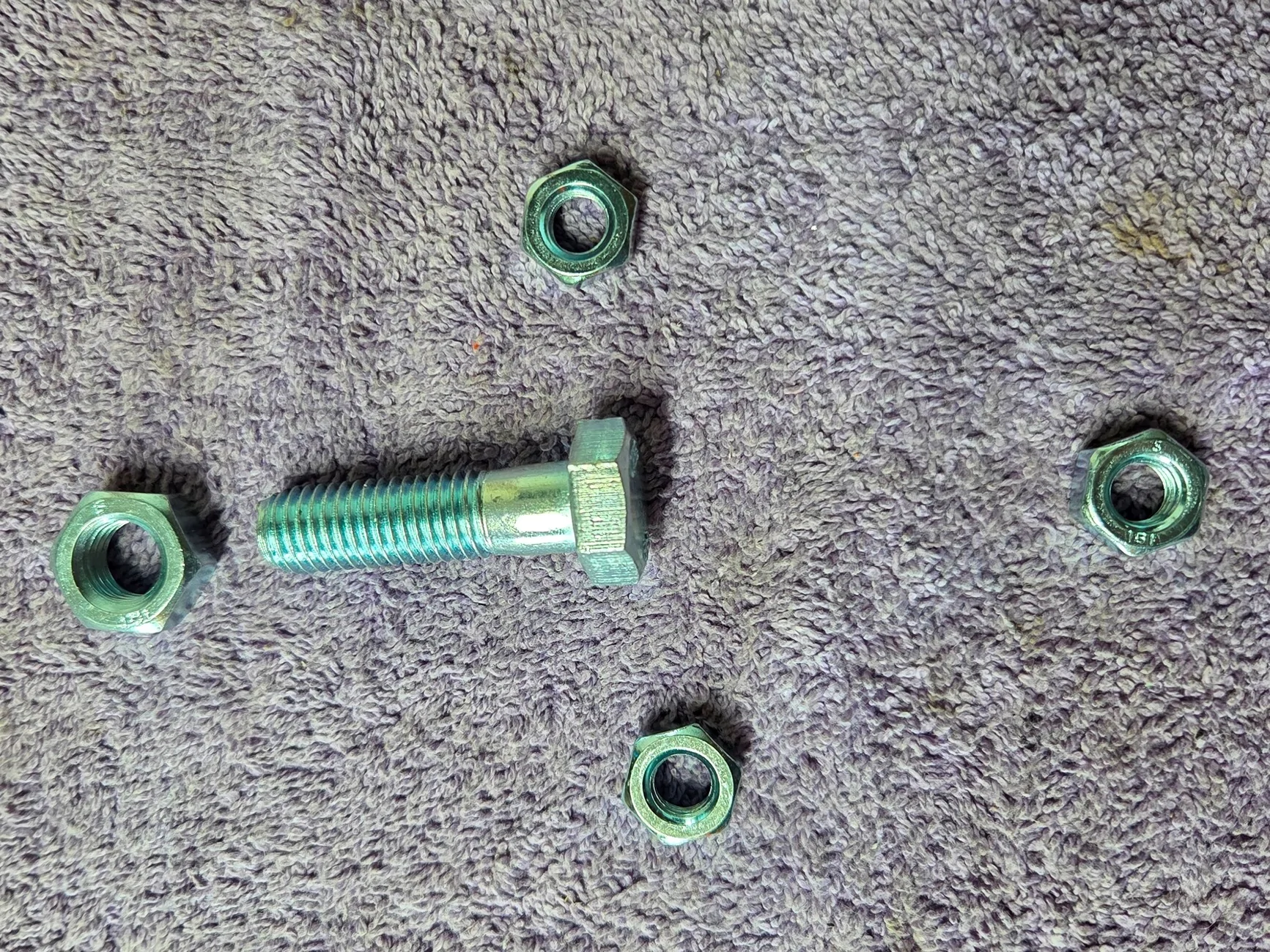
Plate secured to tower, adjusted to positive camber limit. Note the bolt is a bit outboard of the hole center. I measured +0.6° camber from OEM (at tower hole center).
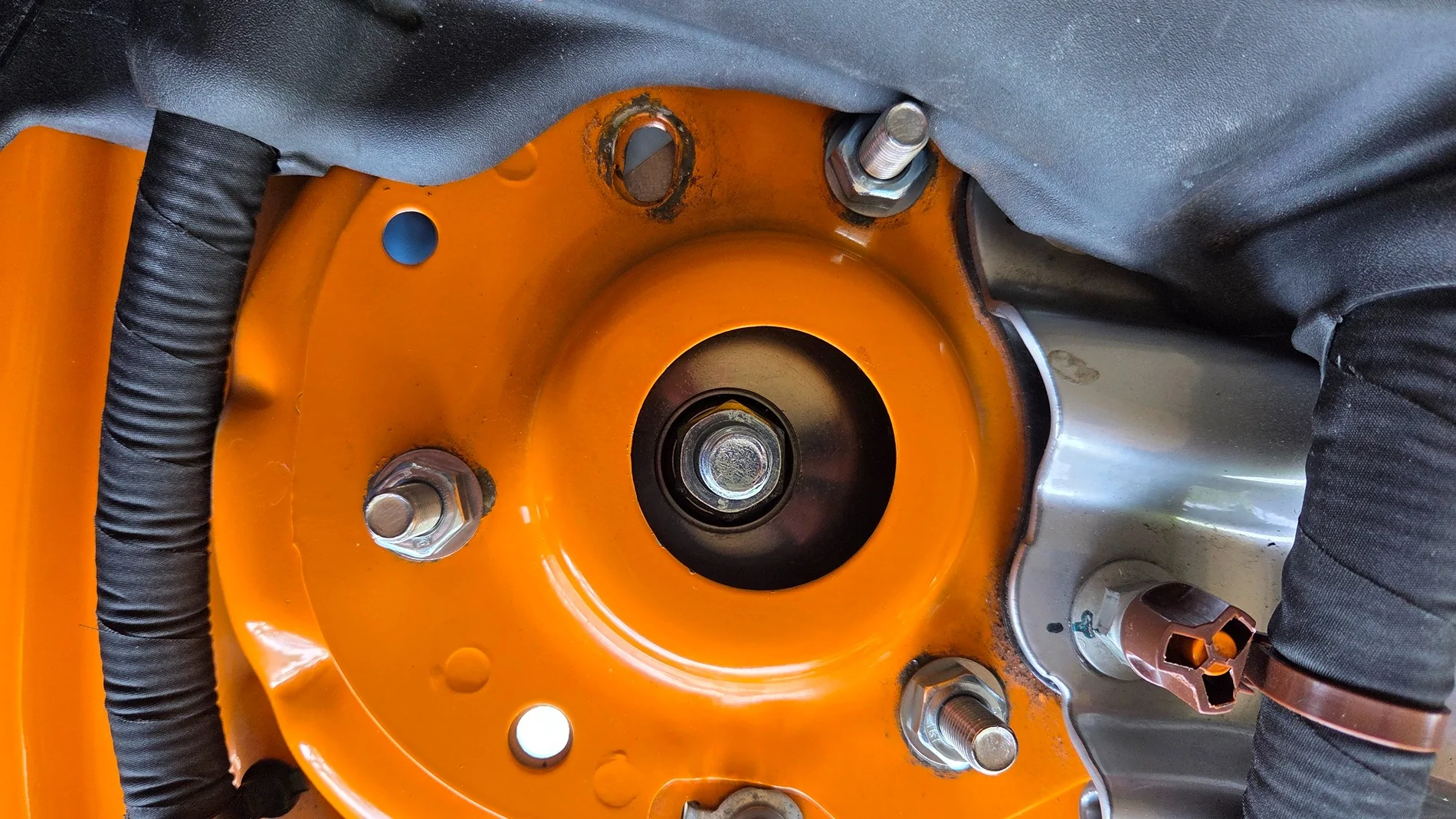
Plate adjusted to negative until bolt touches the tower hole.
Marking profile of notch.
Using Dremel cutoff wheel to remove some of the notch.
Breaking out the little triangle piece.
Holding the Dremel tool cutoff wheel at an angle to effectively remove more material and with a round profile.
5/8” round file for smoothing out the notch.
All seems well with this result.

I use a 10mm deep socket on a nutdriver handle to change camber. This photo shows that the notch clears the nutdriver. However, the car is jacked up and the wheels straight ahead.
Once the car is lowered and steering operated lock-to-lock, I discovered that the strut shaft wanders around a larger area than was provided by this initial notch size.
Ultimately, I had to re-mark with the car on the ground and steering operated lock-to-lock to determine a slightly different notch center and size. Much more filing and checking ensued. This is when I reconsidered the option of the hole saw.
Final result: smooth and painted notch, properly located and sized. <2 photos>
Old drawing circle template helped with marking. <photo >
Up next: Additional information unique to Steeda camber plates
Sponsored
Last edited: