Rodpwnz
Well-Known Member
- Joined
- Oct 14, 2019
- Threads
- 6
- Messages
- 284
- Reaction score
- 239
- Location
- SF Bay Area
- First Name
- Rod
- Vehicle(s)
- 2018 A10 PP1 401A GT
- Thread starter
- #1
Hi Everyone,
Skip to "The Project" below for the why, the how and the actual project.
I want to start by saying that I have learned a great deal through this forum and its members, so thank you to all who have provided information along the way. I would not have been able to start this, or achieve this without you.
That said, I am still a complete noob when it comes to car drivetrain modifications of this sort, and did not(still don't) have the proper tools for this project, so please bear with me on the crude and unconventional methods I use. Also, in my great wisdom, I've decided to start this write up and share my progress near what I believe to be the end.
I'll explain what I am doing and why: I bought my 2018 PP1 mustang GT with 10r80 as a daily sports car, with the expectations that it was track ready. Spoiler alert, it wasn't track ready. Many of us now know that one of the biggest issues is that the transmission overheats at 225F+. The transmission has an internal thermostat inside that starts the flow of trans fluid to the cooler at 190F, slowly opening to full flow by 210F. This OEM cooling setup has proven completely inadequate, even just casual track driving, so it only takes a few laps to hit or exceed the 225F limit. I bought and had installed a larger Mishimoto cooler in hopes to keep temps down enough for a 20 minute session, but it still wasnt near enough.
The problem lies with the incredibly high 190F OEM thermostat inside the transmission. It does not give you enough time/room until hitting the 225F limit. So I've started a project to bypass/delete the internal thermostat, and install my own external thermostat at a lower, yet safe starting temp of 160F. The reason for the 160F thermostat is that the trans does not operate well when too cold. At what exact temperature is trans performance optimal or is trans too cold, I don't know. I know that without a thermostat of some sort, the trans would not be healthy. What I do believe, is that 160F is an optimal middle ground and relatively close to the 190F OEM while giving me plenty of room/time for heat build up. Worst case scenario, if the 160F is still too high, I can swap to 140F without much hassle.
I could have taken the car to a performance shop to do all this for a couple grand or so, but I've always been the type to want to do things just to prove to myself that I can. Especially after years of seeing members in here DIY their own projects - consider me inspired. I've also recently gotten a remote job, so now I'm not commuting hours a day and don't need to rely on my car for work. BIG PLUS - I've moved from apartment to house with garage, so that was table stakes. I did not have this opportunity before, so here I am seizing my chance and taking a leap of faith with my own abilities.
This project started a couple months ago - life gets in the way: sometimes I'm just tired, waiting for parts, all the boys are online to game, fiance wants to spend some quality time, traveling during weekends, house shopping, need time to think/mull ideas over, social gatherings, whatever else. Generally, without external factors, my mental and enthusiast capacity to wrench is limited to a few hours at a time. Physically, I'm not very flexible and have a bad shoulder so those don't help either. I used to think I would be game for a Factory five kit or a real project car - grandiose and ambitious goals, but difficult realities. Who knows, after this project, maybe I actually could.
The Project
Why: Need to keep transmission under 225F
What: Custom thermostat start at 160F instead of OEM 190F
How: Bypass internal themostat, fabricate custom cooler lines and external 160F thermostat.
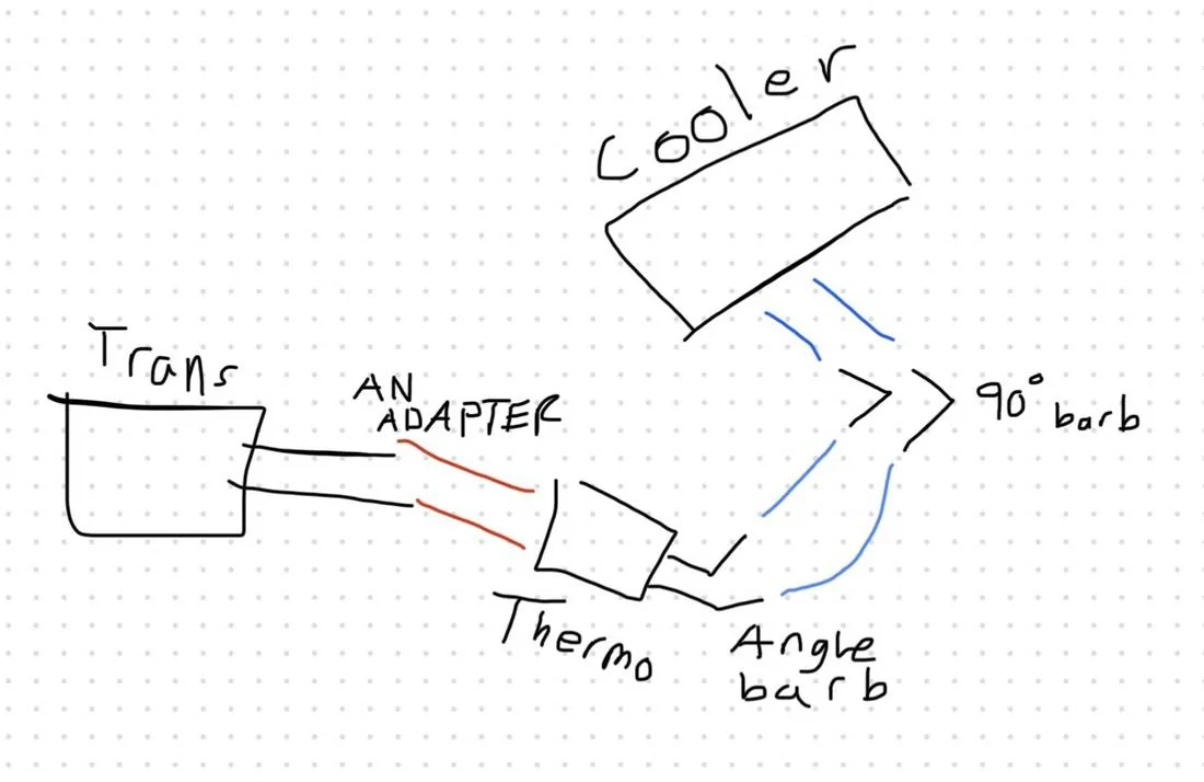
Here is a crude sketch I made of my plan below. I am still contemplating 90 degree barb at end, or if I can simply bend the rubber enough. I'm leaning bend without kink.

and here is an official diagram of trans lines and flow from trans, #2 is where the quick disconnect is and where I am making my modifications in the lines to the cooler.

Tools and items purchased/needed:
4x HF 6TON jack stands
1x HF low profile, long reach 3TON jack
1x Metal Jack pinch weld pad
4x Rubber jack stand pads
1x Improved Racing brand 165F full size/flow Thermostat(P/N: FSM165)
4x -8AN to ORB fittings
2x -8AN to 1/2 inch hard line adapter
2x -8AN to 1/2 inch straight barb
2x -8AN to 1/2 inch 45 angle barb
2x -8AN to 1/2 inch 90 angle barb
1x 10FT CPE transmission hose from Evil Energy
8x Belmetric 19mm spring clamp
1x Coyote direct 10r80 thermostatic bypass
1x LMR 10r80 fluid, gasket and filter kit
1x Fluid transfer pump with small tube
1x Wrench with socket set
1x Pipe cutter tool
1x Drill and bit set
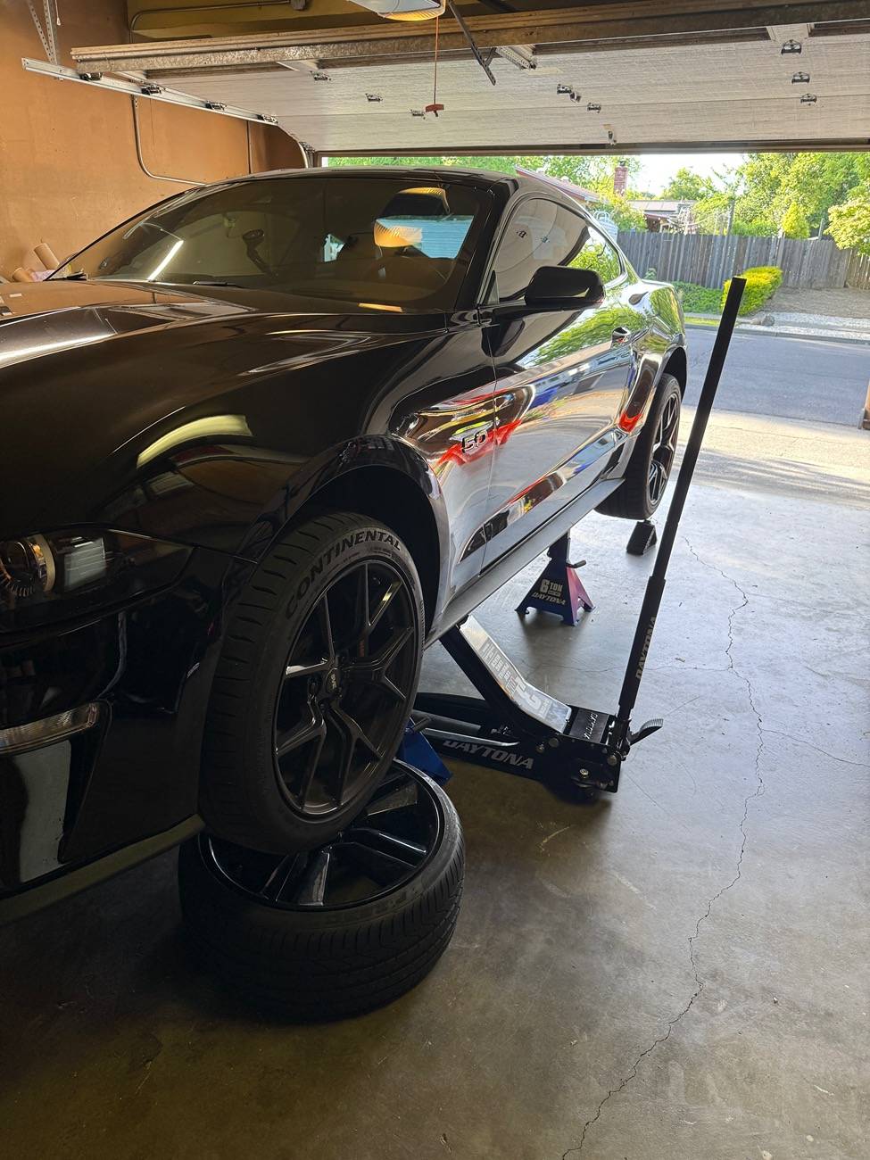
Believe it or not, I was doubting my process to jack up the car on all 4's even after reviewing videos and research online about how to do it. I jacked one side up half way, then the other all the way, and then the original side all the way up too. I tested this out multiple times. I warmed the car up to full operating temp before jacking it up for a final time, making sure to keep the car level and verifying car is secured. I still keep the jack under car as back up, plus couple spare wheels I have under the front two wheels just in case. In the beginning, I was afraid of getting completely under the car, but quickly got used to it. The 6 TON HF give me around 2 feet of clearance under the car, which is very helpful!

Got under to check trans oil levels near operating temp of 200F(it was at 175F) - the trans dipstick is positioned terribly, and it was torqued on insanely tight. I could not get it off myself...first snag on the project, so I took it to a local shop to loosen it for me. They made quick work of it. Fluid looked good in between level 5 and 6 on the dipstick.
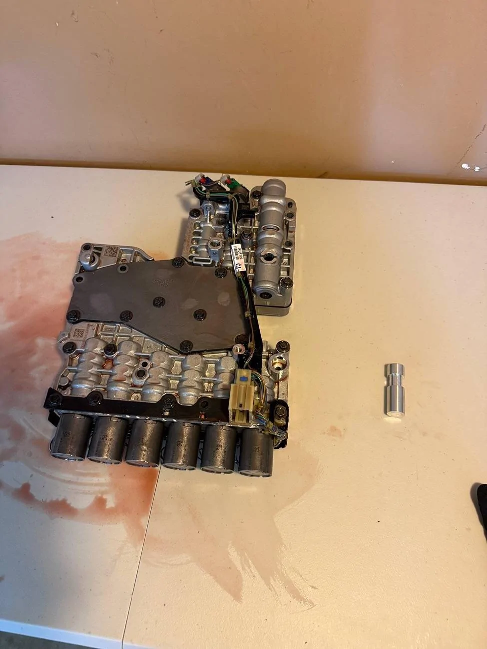
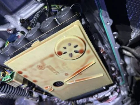
Now that dipstick is out, I tried to pump the fluid out using a fluid transfer pump through the disptick hole. Didn't work very well. I got maybe a couple quarts out, but in the end decided to unbolt the pan and drop/tilt one end to pour fluid out into oil catch. After it mostly spilled out, I unbolted the rest of the trans pan and poured the rest out. In the picture below you can see some clutch material stuck to the magnet - from what I've seen it seems normal, maybe a bit on the higher side... let me know what you think.

Then I removed the trans filter and unbolted the valve body. Took the valvebody to my work bench(Lifetime plastic folding table ) and opened it up following along with Haynes DIY manual, and a scott richardson video. I had already purchased a thermostatic bypass, you can get it from Scott's instagram or through Coyote Direct. I make it sound easy, but embarrasingly enough, whilie worrying about everything else being done right, I goofed by overtorquing the OEM etorx bolts....by a lot, to yield. With the help of local dealer, I ordered replacement bolts for $50 online - another delay. Replaced OEM overtorqued bolts with fresh new ones and at proper torque. Was a bit sketched out since the replacements are normal hex bolts, not eTorx, and they are only threaded half way despite being OEM replacment by SKU/PN ....turns out, the valve body is only threaded on the bottom half anyways! Live and learn!


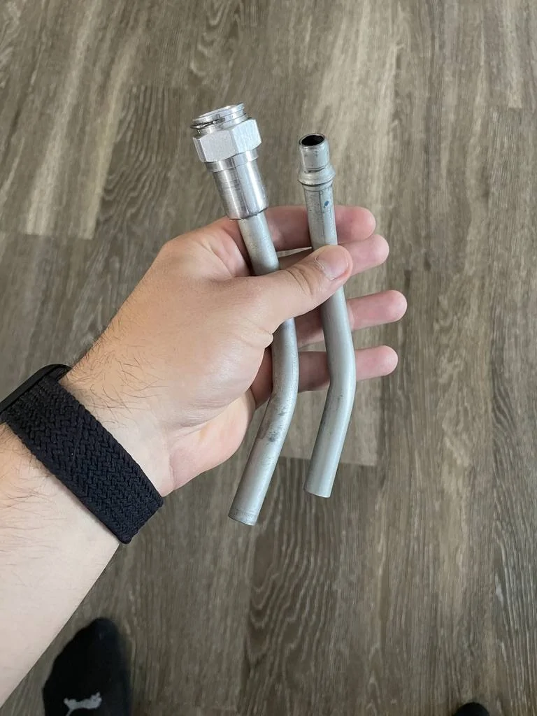
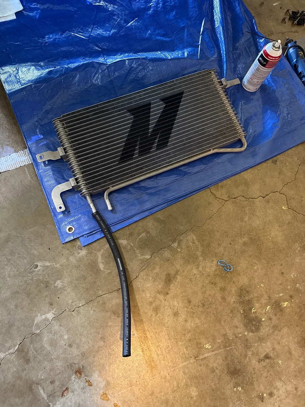
So now it was time to start removing the OEM trans lines, but instead of removing them entirely from trans case IN/OUT ports all the way to cooler, I opted to keep as much of the OEM steel hard line from trans to cooler as possible. There is a section closer of cooler lines to the front of the car and the transmission cooler that has quick disconnect attachment points for in/out steel hardlines. This quick disconnect point is also where my current mishimoto cooler uses their own hard lines to replace the OEM section to OEM cooler. When I had the mishi hard lines installed, I kept the OEM lines that were removed and had them cut so I could convert them eventually for this project.
I needed to remove the current Mishimoto hard lines from cooler and from the quick disconnect points, however due to the bends and space constraint, there was no way to effectively remove it intact without removing the trans cooler as well. First I needed to disconnect the Mishimoto cooler lines from both ends - I started with using regular pliers to hold open the spring clamps, while tugging on the rubber mishi hose connected to trans cooler. Difficult but eventually with enough muscle and cursing they came free.

That was for the rubber hose over mishi cooler barbs, I now have to remove the hard line quick disonnect points towards the trans side. I did not know how QD connects worked, but learned for this project. There is a small metal retaining clip on the larger end of the QD that holds the smaller "barb" in place inside the larger end. I used a pick to get the clip out for IN and OUT lines. Then pulled the lines apart. I had fiance help me since its a tight space and her hands are much smaller than mine. I held onto one end from below the car and she yanked the other end through top of engine bay.
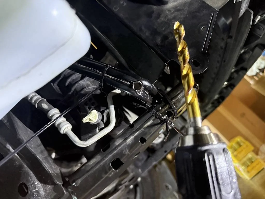
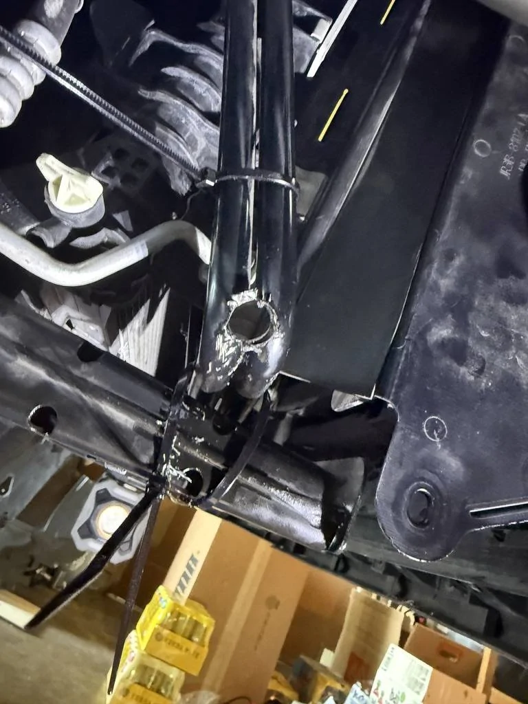
Ok great, now both ends of the mishimoto hard lines are free - back to the initial problem of it being too tight to remove the lines without removing cooler. I already had/have parts sprawled all over my garage and didnt want to add more slippery trans fluid spills and a cooler to the pile. So, after contemplating futher, I decided I would cut the hard lines at the main bend, to create two smaller, straighter pieces that I can easily remove. The hardlines are touching side by side, and welded together at points. I had a dremel with cutting discs, a hand saw, bolt cutters that are too small for 1/2 inch, and a drill with bits. Dremel with cutting disc may pose fire risk with trans fluid and sparks, hand saw is too slow and physical, and not much room to work. I decided to simply drill a hole inbetween the two, where they meet and are held together at the bend. I started with smaller bit, then slowly increased bit size until the hole had cut through most of the lines, I then used the bolt cutters to clip the slivers on the edges that were holding it together. Once separated, both slipped through gaps super easy.
Now that the Mishi lines have been removed, I can work using the original customized/cut OEM hard lines to replace it. For both OEM IN/OUT hard lines, I used a 1/2 inch hard line to -8AN adapter, then an -8AN to hose barb adapter. Then 1/2 inch CPE hose for 10 inches, which is too long for now but I will cut once I have the rest of the lines measured and finalized. I used 19mm belmetric spring clamps to keep hose on barb, they barely fit, but according to belmetric that is how tight you want them. I hope I tighted the AN fittings well enough...dont want to deal with any leaks.
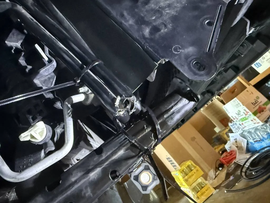
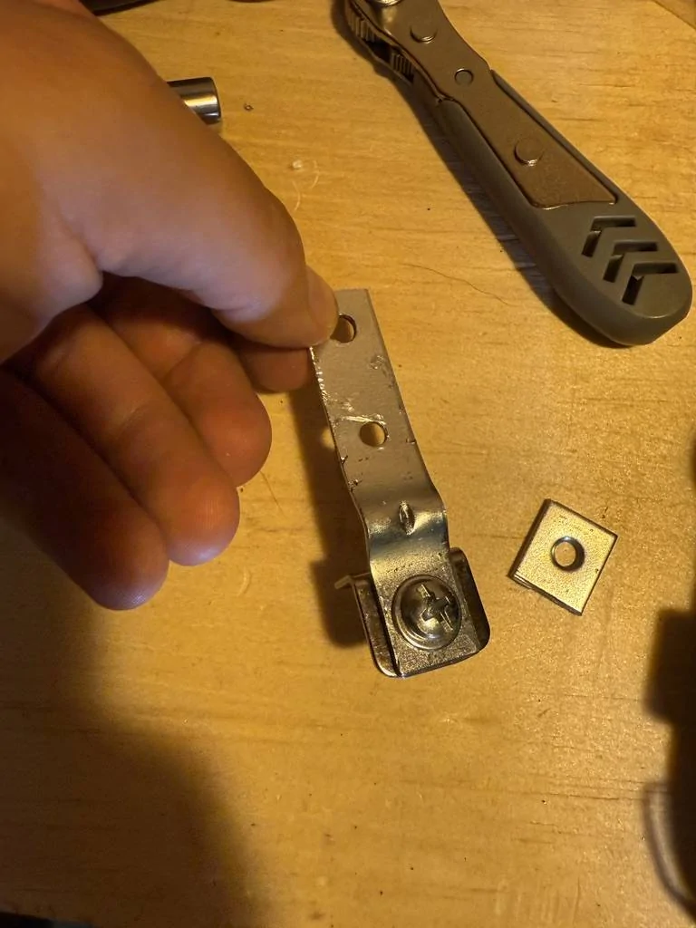
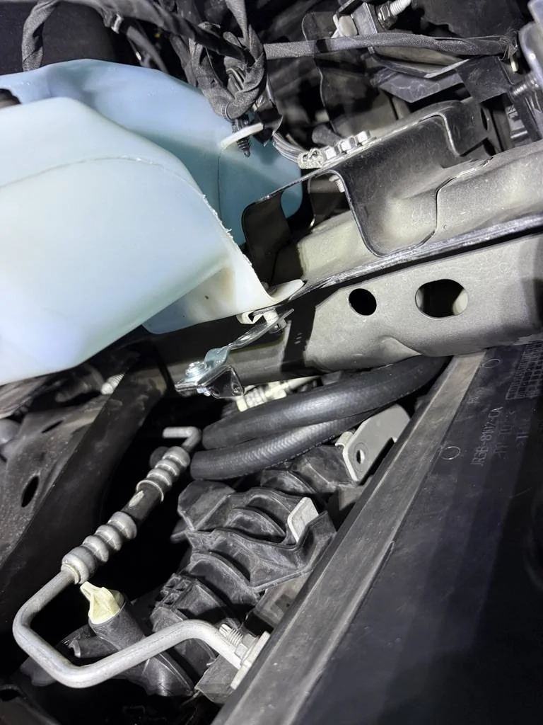
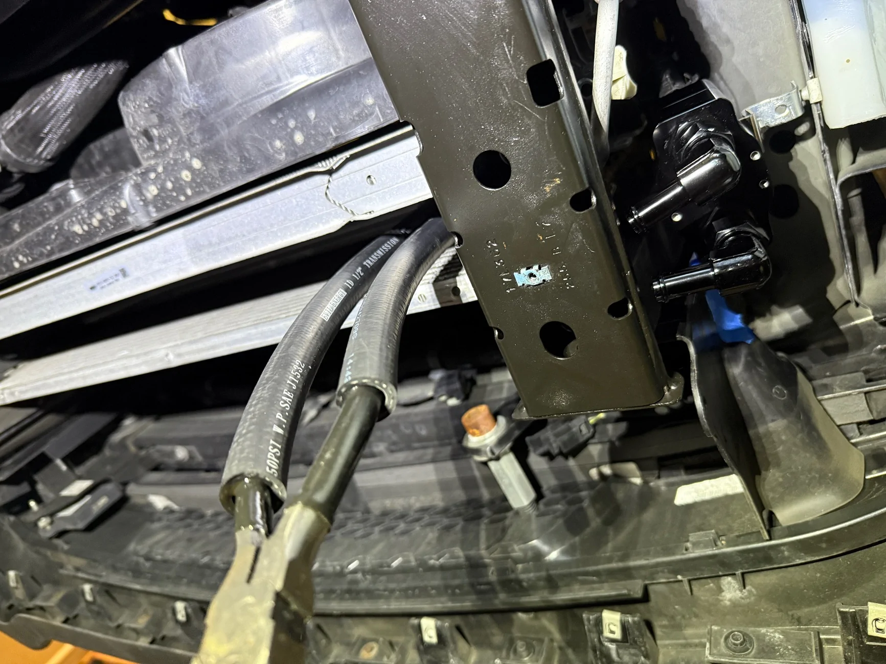
I have attached the above custom QD to AN to Hose line to the OEM QD point along the hard line, and now have to figure out where to mount the thermostatic bypass valve. I need to position it first, then fabricate a bracket....after much trial and error, I believe I've accomplished that. I've never had to cut, bend, grind and drill metal as much as I have this week! Really cool stuff to be able to say, "I fabricated that custom metal bracket". It started with home depot 90 degree zinc coated steel brackets... then I bent it straight-ish with two pliers. Then I uga buga hammered it mostly flat against my garage floor. Then I drilled one of the holes bigger to fit over an existing OEM bolt on the car to mount to. Then I cut the end a bit shorter to match the positioning and length I needed for the thermostat to sit right. Finally, I bent it all up multiple different ways out of trial and error until I finally bent it into the right shape. Behold, my creation!
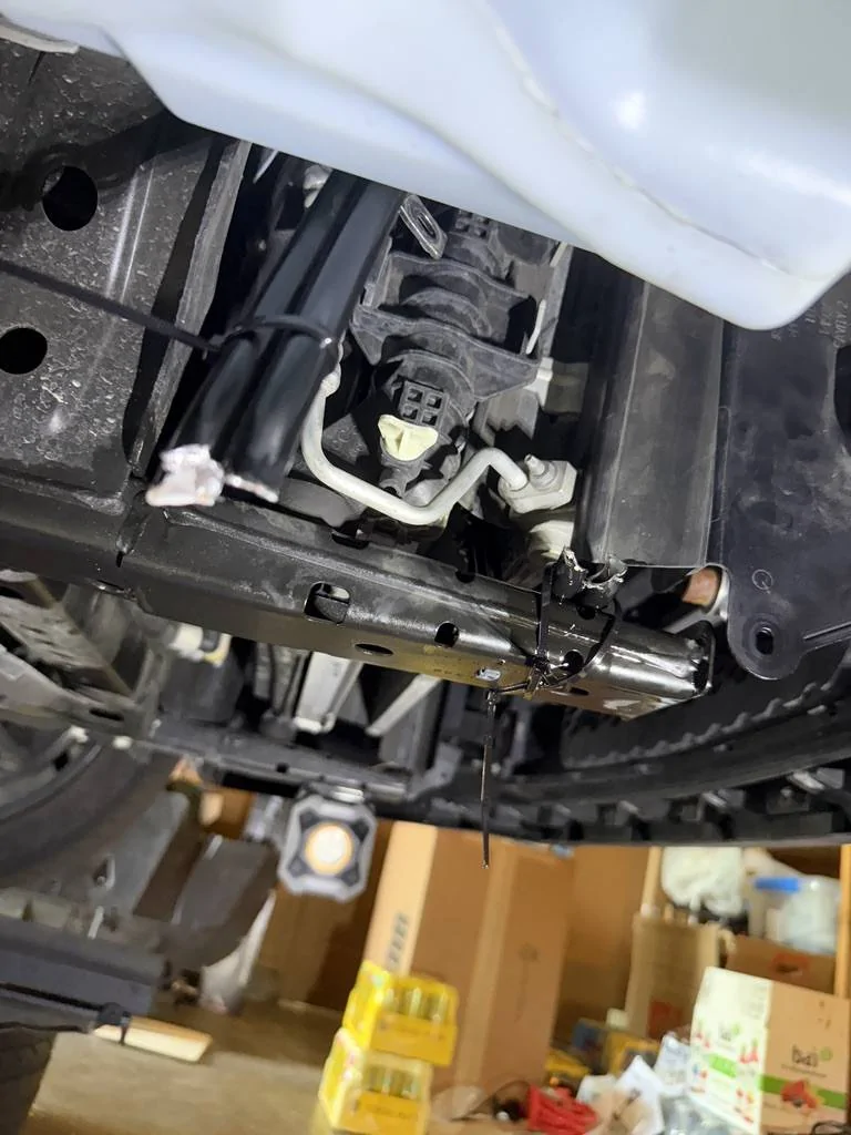
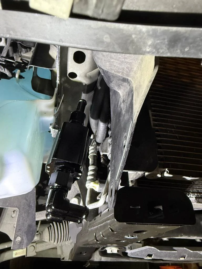
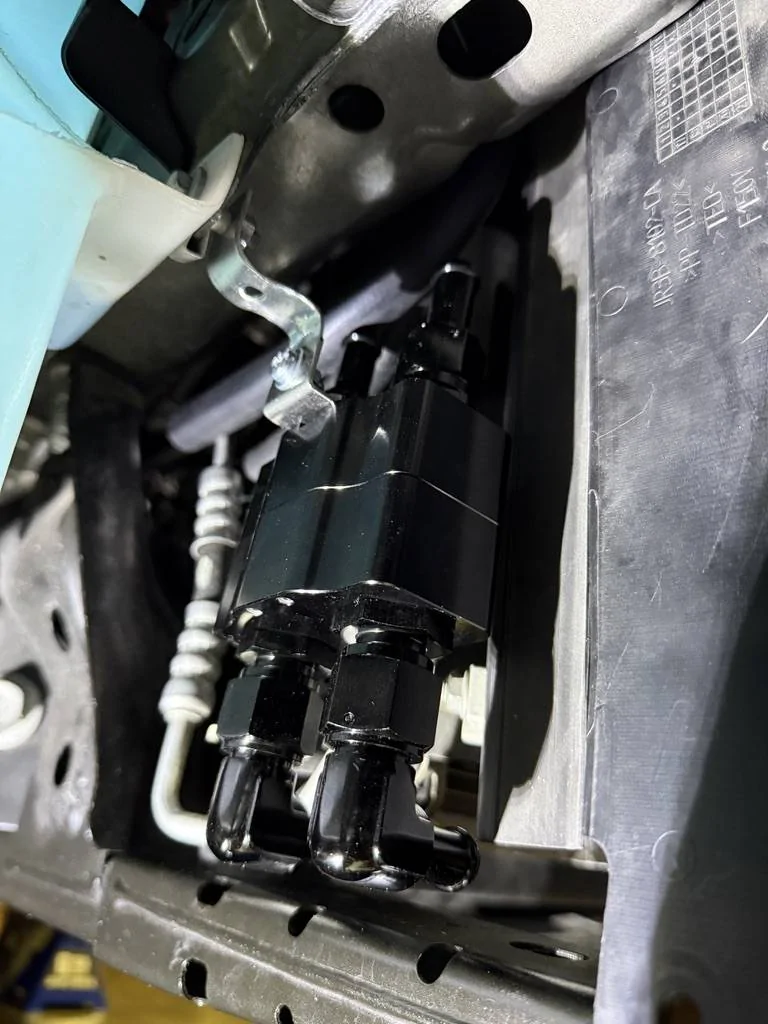
Almost there! Too long and too far out still - notice how the 90 degree barbs wont clear the frame below, and the straight barbs above and too far out. Needs to be an inch or so closer towards inside of car for hose to fit well. You can see the hoses tucked away above in the side profile picture:
And here we are now!
A few questions I have:
1. For vibrations, should I use threadlocker(Blue?) or locking washers(nord-lock)?
2. Is there anything I've missed or overlooked so far? Nothing is permanent yet and still reasonably accessible.
08/02/2025 UPDATE: Project is finished!
Picking up from the last update—once I removed the hard lines, I figured I could just pull the trans cooler to make slipping the CPE hoses onto the barbs easier. The space was just too cramped to do it while the cooler was still mounted.
Well... I was wrong. Removing the trans cooler turned into a huge pain, especially with the AC condenser in the way. I didn’t disconnect any AC lines, but had to carefully push the condenser forward after a couple hours of delicate Dremel work on a plastic tab Ford definitely could’ve designed better. Not many pics, but trust me—it sucked.
With the cooler finally out, fitting the CPE hoses was straightforward. I used rubber/CPE-safe silicone lube, softened the hose ends in hot water, and slipped them over the barbs with ease. I reused the OEM clamps (constant-tension style), but had to lightly Dremel the hose exterior to seat them properly over the underlying barb. Only using constant/spring tension clamps from Bel Metric, OEM, or Mishimoto—no worm gear clamps. If I had to do it again, I’d size the clamps 1–2mm LARGER than Bel Metric’s recommended spec.
I left the trans cooler attached hoses a little long to trim once everything’s reinstalled and I can confirm measurement/fitment. Rather than force them onto the barbs while attached to the thermostat (mission impossible), I removed the AN barb fittings from the thermo and slipped them into the hanging hoses first. Then I reinstalled and tightened them into the thermostat using two painter’s tape wrapped wrenches - MUCH EASIER!
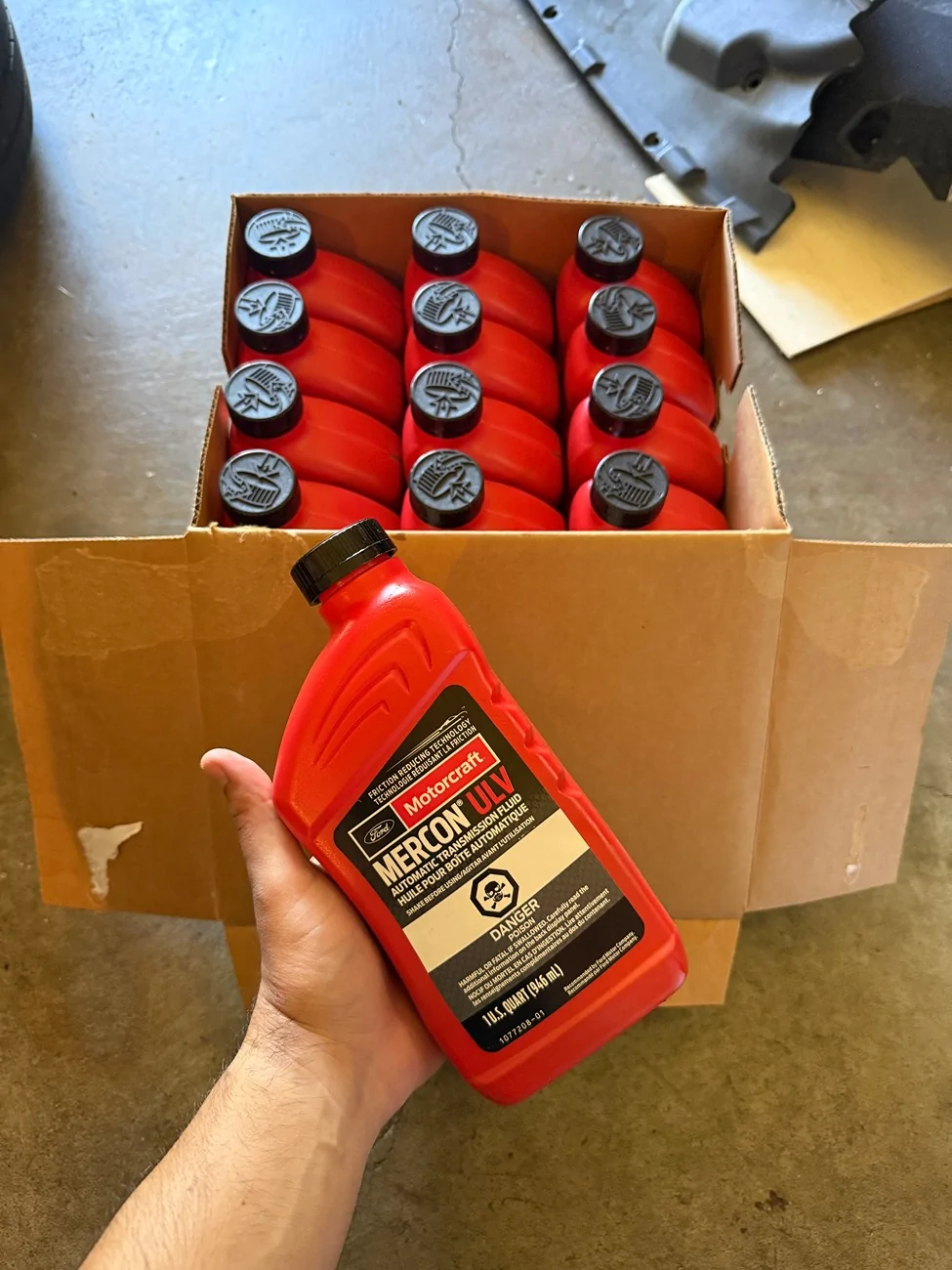
With the custom part of the project finally wrapped up, I reinstalled the transmission filter, swapped in a new gasket (wasn’t necessary, but had a spare), and refilled with Mercon ULV ATF. Spec calls for 4.8L on a pan drop, but since the cooler was empty and I had some slow drip losses over time, I went with 5.7L.
Here is the guide I'm following for 10r80 transmission fluid fill up: https://www.mustang6g.com/forums/attachments/10r80-fluid-level-disptick-info-pdf.469336/
UPDATES ADDED IN CHRONOLOGICAL ORDER TO THIS ORIGINAL THREAD/POST:
For Transmission fill up:
I torqued pan and extras to spec, and started the car. After cycling through P–N–R–D for 5-10 seconds each, I noticed a funky smell... I got under the car and saw that ATF had spilled on the cats and was lightly smoking. I checked the dipstick while it was still warming up and I was down there. I was also hearing an intermittent humming sound from trans - not sure if that was there before or not...
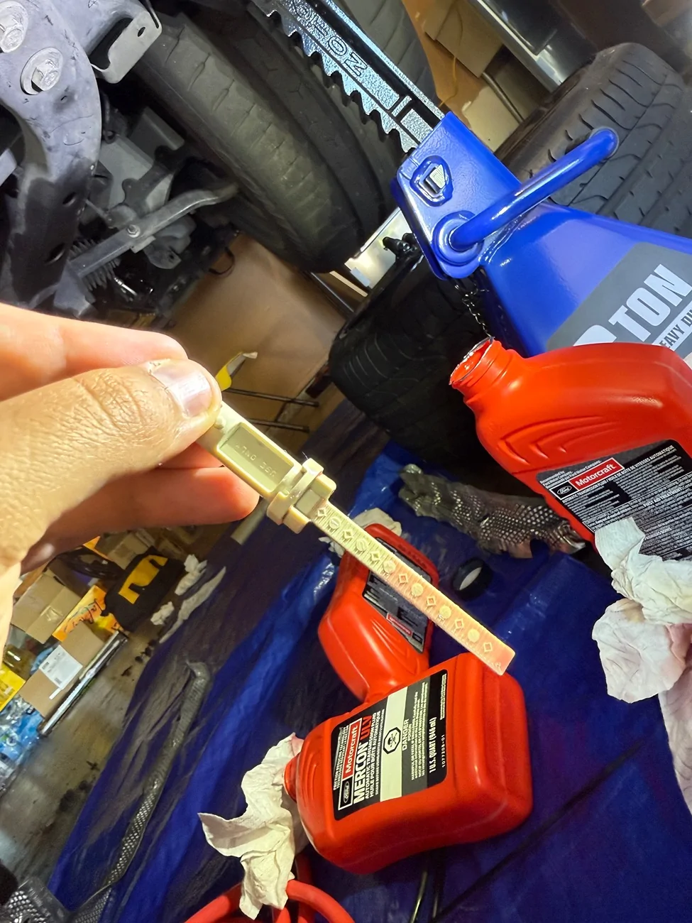
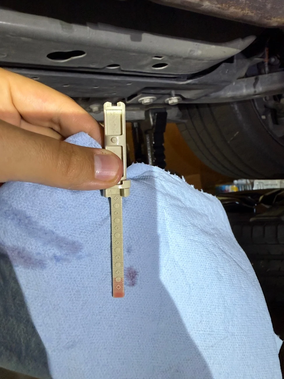
Engine at idle, trans in park. I check dipstick and it's completely dry except for maybe a bit up high where it touched some fluid at the fill hole. Here is a picture:
Still the same dipstick reading after adding another quart of ULV fluid, totaling 7QTs. I was worried I would be overfilling since Ford and Haynes manual states 5-6 QT, but after researching more, I'm seeing 7.5-10QTs from other people online. I'll keep adding quarts of fluid and monitoring dipstick reading.
My trans was also making a whirring/humming sound that I don't remember hearing before dropping the pan. Might just be that fluid is low- here is a video of sound:
Another day later:
I am now at a total of 10QTs in and still no fluid showing on dipstick with engine running, car in park. I get Fluid up to level 3 on the dipstick when engine is off. I only have 2 more QTs left and I'll be adding them to see if I can get some to show on dipstick with engine running.
The pump whirring sound is gone now, I assume it was the fluid pick up pump inside transmission trying to suck fluid but level was too low.
After some more contemplating, day gone by and added fluid:
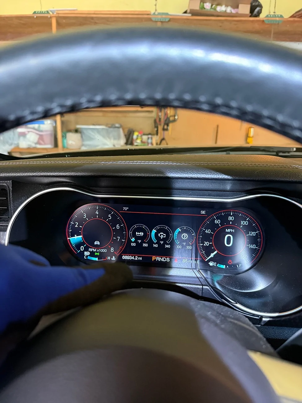
I DID IT! 11QTS of fluid! Now fluid shows on disptick level 6 while engine idle + trans cold. Just as ford requires!
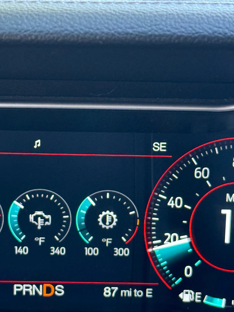
Ford procedure now states I can drive the car or brake torque(on and off 10 seconds) while in air to get trans to temp. Once at temp(200F+, 165F with my thermo), I will check fluid levels again and top up as needed.
I hope I didn’t cause any damage to trans by running engine and cycling through gear modes 5-10 seconds while super low on fluid….
I have one more QT of fluid remaining, and I think I will need it to fill empty trans lines and empty trans cooler. Maybe even another extra quart.
NEW UPDATE:
Regarding driving car, and checking fluid while hot and at temp. In my case, temp would be 165-170F since my new thermostat starts at 160F and is expected to stabilize at around 165F.
I gently drove the car around the block for 15-20 mins, checking for any leaks, fluid, sounds, smells, hard shifts, or unusual occurances. Everything was fine, car shifted amazing, car drove great(3 month old fuel), got up to around 170F stable transmission fluid temp.
I pull into garage, lift car up quickly, level it with 4 jack stands - it's 80F+ days this week and I'm sweating like a pig already. Get under and the cats are extremely hot, I'm cooking under the car and my gloves keep me safe for a few seconds at a time. Curse the ford engineers who didnt add an easier access dipstick.
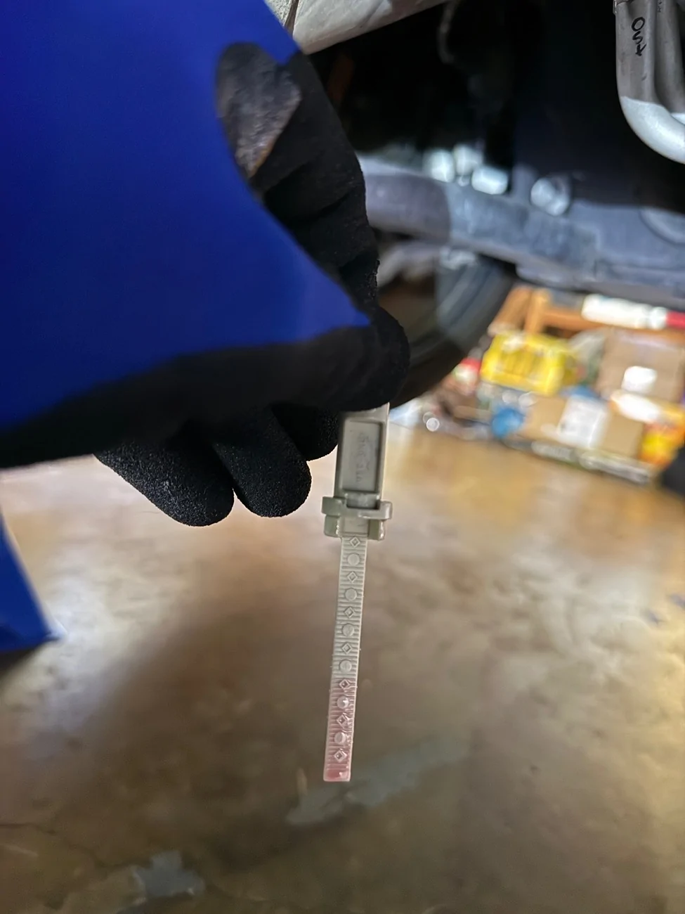
Fluid was exactly where it needed to be - between 4-5 on the dipstick, at 4.5 to be exact.
What a relief!!! Hand torqued the dipstick bolt, and bolted the rest of the undertray back on. In my excitement, over the weekend I drove the mustang over a few hundred miles to see friends and attend events. No leaks, very smooth driving/shifting, temp stayed steady around 170-175F mostly.
At highway, it was usually 170F no matter the ambient temperature(60F-85F), if I drove a little more aggressive, especially off highway, with more shifting, fluid temps would go up to around 180F temporarily.
I have a couple ideas/theories as to why the stabilization temperature of 170F-180F I'm seeing is higher than what improved racing estimated 165F stabilization temp:
1. Our 10r80 puts out SO much heat compared to a traditional automatic transmission, their estimation does not apply as accurately to 10r80.
2. I put the thermostat about 5-8 feet down the hardlines from transmission(sitting at the front of the car, next to radiator) - this causes a delay in flow and cool fluid doesn't come back as quickly as OEM setup. So temp sensor inside shows a higher reading.
I called improved racing to dig a bit deeper and they claimed my setup should see <5F delta from their 165F. So I guess, 170F is close but still a bit higher; 175F-180F is way higher.
These are not real issues in my opinion, since to be honest, I want the temps to be higher when street driving anyways. I also still get the FULL OPEN/FLOW thermostat at 180F instead of 210F like OEM, so my track temps should be cooler and with longer time under full flow cooling.
I think the only update I have left is to go to the track to fully test it out and report back results. I will say, I have been doing many WOT pulls, a couple sideways turns, and lots of normal driving miles without issues so far. I have a lot of confidence in the durability and effectivenesss of this custom cooling solution and project!
Thank you for following along, thank you for your help, thank you for your support - I would have never have taken on such a project without this community.
Update 10/24//2025: Project was an absolute SUCCESS!
At long last, I finally got the car out to a track day to test out my thermostat and transmission cooling. I am very happy with the below results!
Track: Thunderhill West loop - 2 mile CCW
Weather: Sunny
Ambient temps: 70-80F throughout day
Trans temps: 190F MAX
Diff temps: 230F MAX
Engine CHT: 230F MAX
Things to note - this was a shorter track than I'm used to and temps were lower than what I generally experienced transmission cooling issues with. I also short shifted out of habit and was generally less familiar with this track. I plan on going to Thunderhill East loop next month to try it out on a track I'm much more familiar with.
HUGE shout out to Trent Musser! I came to him a couple days before my track day with a few issues on the car and he took time away from other work to get me sorted. He spent HOURS getting me track ready, all on last minute notice to him. Now I'm not saying do this shit to him, but understand the integrity, passion and care for him to do this considering my dire situation. Without him, I would not have made this track day in time. If you're in SF bay area and want the best, I highly recommend giving him a ring. Trent Musser Motorsports: (707)-655-2909. Tell him I sent you.
Skip to "The Project" below for the why, the how and the actual project.
I want to start by saying that I have learned a great deal through this forum and its members, so thank you to all who have provided information along the way. I would not have been able to start this, or achieve this without you.
That said, I am still a complete noob when it comes to car drivetrain modifications of this sort, and did not(still don't) have the proper tools for this project, so please bear with me on the crude and unconventional methods I use. Also, in my great wisdom, I've decided to start this write up and share my progress near what I believe to be the end.
I'll explain what I am doing and why: I bought my 2018 PP1 mustang GT with 10r80 as a daily sports car, with the expectations that it was track ready. Spoiler alert, it wasn't track ready. Many of us now know that one of the biggest issues is that the transmission overheats at 225F+. The transmission has an internal thermostat inside that starts the flow of trans fluid to the cooler at 190F, slowly opening to full flow by 210F. This OEM cooling setup has proven completely inadequate, even just casual track driving, so it only takes a few laps to hit or exceed the 225F limit. I bought and had installed a larger Mishimoto cooler in hopes to keep temps down enough for a 20 minute session, but it still wasnt near enough.
The problem lies with the incredibly high 190F OEM thermostat inside the transmission. It does not give you enough time/room until hitting the 225F limit. So I've started a project to bypass/delete the internal thermostat, and install my own external thermostat at a lower, yet safe starting temp of 160F. The reason for the 160F thermostat is that the trans does not operate well when too cold. At what exact temperature is trans performance optimal or is trans too cold, I don't know. I know that without a thermostat of some sort, the trans would not be healthy. What I do believe, is that 160F is an optimal middle ground and relatively close to the 190F OEM while giving me plenty of room/time for heat build up. Worst case scenario, if the 160F is still too high, I can swap to 140F without much hassle.
I could have taken the car to a performance shop to do all this for a couple grand or so, but I've always been the type to want to do things just to prove to myself that I can. Especially after years of seeing members in here DIY their own projects - consider me inspired. I've also recently gotten a remote job, so now I'm not commuting hours a day and don't need to rely on my car for work. BIG PLUS - I've moved from apartment to house with garage, so that was table stakes. I did not have this opportunity before, so here I am seizing my chance and taking a leap of faith with my own abilities.
This project started a couple months ago - life gets in the way: sometimes I'm just tired, waiting for parts, all the boys are online to game, fiance wants to spend some quality time, traveling during weekends, house shopping, need time to think/mull ideas over, social gatherings, whatever else. Generally, without external factors, my mental and enthusiast capacity to wrench is limited to a few hours at a time. Physically, I'm not very flexible and have a bad shoulder so those don't help either. I used to think I would be game for a Factory five kit or a real project car - grandiose and ambitious goals, but difficult realities. Who knows, after this project, maybe I actually could.
The Project
Why: Need to keep transmission under 225F
What: Custom thermostat start at 160F instead of OEM 190F
How: Bypass internal themostat, fabricate custom cooler lines and external 160F thermostat.
Here is a crude sketch I made of my plan below. I am still contemplating 90 degree barb at end, or if I can simply bend the rubber enough. I'm leaning bend without kink.
and here is an official diagram of trans lines and flow from trans, #2 is where the quick disconnect is and where I am making my modifications in the lines to the cooler.

Tools and items purchased/needed:
4x HF 6TON jack stands
1x HF low profile, long reach 3TON jack
1x Metal Jack pinch weld pad
4x Rubber jack stand pads
1x Improved Racing brand 165F full size/flow Thermostat(P/N: FSM165)
4x -8AN to ORB fittings
2x -8AN to 1/2 inch hard line adapter
2x -8AN to 1/2 inch straight barb
2x -8AN to 1/2 inch 45 angle barb
2x -8AN to 1/2 inch 90 angle barb
1x 10FT CPE transmission hose from Evil Energy
8x Belmetric 19mm spring clamp
1x Coyote direct 10r80 thermostatic bypass
1x LMR 10r80 fluid, gasket and filter kit
1x Fluid transfer pump with small tube
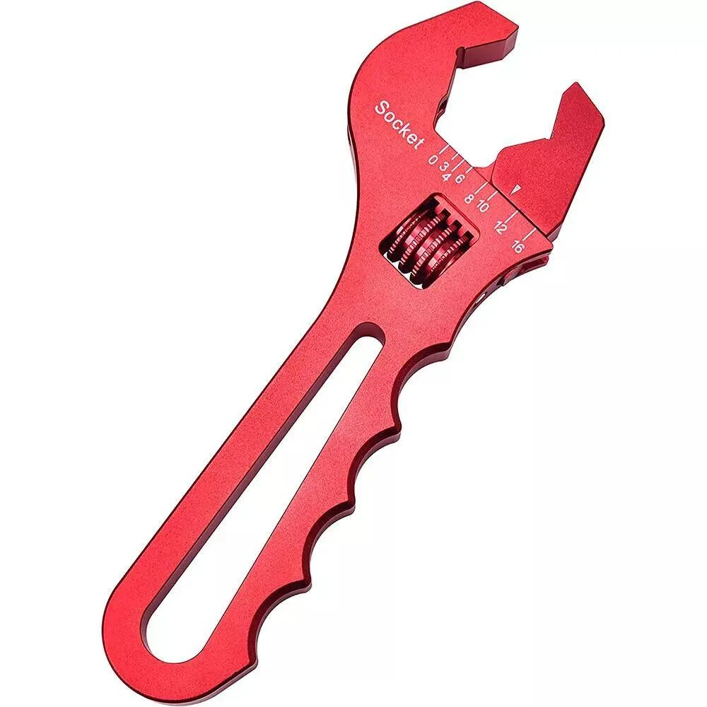
1x Wrench with socket set
1x Pipe cutter tool
1x Drill and bit set
Believe it or not, I was doubting my process to jack up the car on all 4's even after reviewing videos and research online about how to do it. I jacked one side up half way, then the other all the way, and then the original side all the way up too. I tested this out multiple times. I warmed the car up to full operating temp before jacking it up for a final time, making sure to keep the car level and verifying car is secured. I still keep the jack under car as back up, plus couple spare wheels I have under the front two wheels just in case. In the beginning, I was afraid of getting completely under the car, but quickly got used to it. The 6 TON HF give me around 2 feet of clearance under the car, which is very helpful!
Got under to check trans oil levels near operating temp of 200F(it was at 175F) - the trans dipstick is positioned terribly, and it was torqued on insanely tight. I could not get it off myself...first snag on the project, so I took it to a local shop to loosen it for me. They made quick work of it. Fluid looked good in between level 5 and 6 on the dipstick.

Now that dipstick is out, I tried to pump the fluid out using a fluid transfer pump through the disptick hole. Didn't work very well. I got maybe a couple quarts out, but in the end decided to unbolt the pan and drop/tilt one end to pour fluid out into oil catch. After it mostly spilled out, I unbolted the rest of the trans pan and poured the rest out. In the picture below you can see some clutch material stuck to the magnet - from what I've seen it seems normal, maybe a bit on the higher side... let me know what you think.
Then I removed the trans filter and unbolted the valve body. Took the valvebody to my work bench(Lifetime plastic folding table
) and opened it up following along with Haynes DIY manual, and a scott richardson video. I had already purchased a thermostatic bypass, you can get it from Scott's instagram or through Coyote Direct. I make it sound easy, but embarrasingly enough, whilie worrying about everything else being done right, I goofed by overtorquing the OEM etorx bolts....by a lot, to yield. With the help of local dealer, I ordered replacement bolts for $50 online - another delay. Replaced OEM overtorqued bolts with fresh new ones and at proper torque. Was a bit sketched out since the replacements are normal hex bolts, not eTorx, and they are only threaded half way despite being OEM replacment by SKU/PN ....turns out, the valve body is only threaded on the bottom half anyways! Live and learn!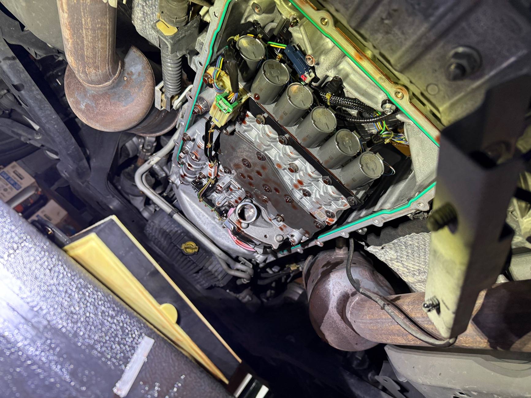


So now it was time to start removing the OEM trans lines, but instead of removing them entirely from trans case IN/OUT ports all the way to cooler, I opted to keep as much of the OEM steel hard line from trans to cooler as possible. There is a section closer of cooler lines to the front of the car and the transmission cooler that has quick disconnect attachment points for in/out steel hardlines. This quick disconnect point is also where my current mishimoto cooler uses their own hard lines to replace the OEM section to OEM cooler. When I had the mishi hard lines installed, I kept the OEM lines that were removed and had them cut so I could convert them eventually for this project.


I needed to remove the current Mishimoto hard lines from cooler and from the quick disconnect points, however due to the bends and space constraint, there was no way to effectively remove it intact without removing the trans cooler as well. First I needed to disconnect the Mishimoto cooler lines from both ends - I started with using regular pliers to hold open the spring clamps, while tugging on the rubber mishi hose connected to trans cooler. Difficult but eventually with enough muscle and cursing they came free.

That was for the rubber hose over mishi cooler barbs, I now have to remove the hard line quick disonnect points towards the trans side. I did not know how QD connects worked, but learned for this project. There is a small metal retaining clip on the larger end of the QD that holds the smaller "barb" in place inside the larger end. I used a pick to get the clip out for IN and OUT lines. Then pulled the lines apart. I had fiance help me since its a tight space and her hands are much smaller than mine. I held onto one end from below the car and she yanked the other end through top of engine bay.


Ok great, now both ends of the mishimoto hard lines are free - back to the initial problem of it being too tight to remove the lines without removing cooler. I already had/have parts sprawled all over my garage and didnt want to add more slippery trans fluid spills and a cooler to the pile. So, after contemplating futher, I decided I would cut the hard lines at the main bend, to create two smaller, straighter pieces that I can easily remove. The hardlines are touching side by side, and welded together at points. I had a dremel with cutting discs, a hand saw, bolt cutters that are too small for 1/2 inch, and a drill with bits. Dremel with cutting disc may pose fire risk with trans fluid and sparks, hand saw is too slow and physical, and not much room to work. I decided to simply drill a hole inbetween the two, where they meet and are held together at the bend. I started with smaller bit, then slowly increased bit size until the hole had cut through most of the lines, I then used the bolt cutters to clip the slivers on the edges that were holding it together. Once separated, both slipped through gaps super easy.


Now that the Mishi lines have been removed, I can work using the original customized/cut OEM hard lines to replace it. For both OEM IN/OUT hard lines, I used a 1/2 inch hard line to -8AN adapter, then an -8AN to hose barb adapter. Then 1/2 inch CPE hose for 10 inches, which is too long for now but I will cut once I have the rest of the lines measured and finalized. I used 19mm belmetric spring clamps to keep hose on barb, they barely fit, but according to belmetric that is how tight you want them. I hope I tighted the AN fittings well enough...dont want to deal with any leaks.


I have attached the above custom QD to AN to Hose line to the OEM QD point along the hard line, and now have to figure out where to mount the thermostatic bypass valve. I need to position it first, then fabricate a bracket....after much trial and error, I believe I've accomplished that. I've never had to cut, bend, grind and drill metal as much as I have this week! Really cool stuff to be able to say, "I fabricated that custom metal bracket". It started with home depot 90 degree zinc coated steel brackets... then I bent it straight-ish with two pliers. Then I uga buga hammered it mostly flat against my garage floor. Then I drilled one of the holes bigger to fit over an existing OEM bolt on the car to mount to. Then I cut the end a bit shorter to match the positioning and length I needed for the thermostat to sit right. Finally, I bent it all up multiple different ways out of trial and error until I finally bent it into the right shape. Behold, my creation!


Almost there! Too long and too far out still - notice how the 90 degree barbs wont clear the frame below, and the straight barbs above and too far out. Needs to be an inch or so closer towards inside of car for hose to fit well. You can see the hoses tucked away above in the side profile picture:

And here we are now!
A few questions I have:
1. For vibrations, should I use threadlocker(Blue?) or locking washers(nord-lock)?
2. Is there anything I've missed or overlooked so far? Nothing is permanent yet and still reasonably accessible.
08/02/2025 UPDATE: Project is finished!
Picking up from the last update—once I removed the hard lines, I figured I could just pull the trans cooler to make slipping the CPE hoses onto the barbs easier. The space was just too cramped to do it while the cooler was still mounted.

Well... I was wrong. Removing the trans cooler turned into a huge pain, especially with the AC condenser in the way. I didn’t disconnect any AC lines, but had to carefully push the condenser forward after a couple hours of delicate Dremel work on a plastic tab Ford definitely could’ve designed better. Not many pics, but trust me—it sucked.
With the cooler finally out, fitting the CPE hoses was straightforward. I used rubber/CPE-safe silicone lube, softened the hose ends in hot water, and slipped them over the barbs with ease. I reused the OEM clamps (constant-tension style), but had to lightly Dremel the hose exterior to seat them properly over the underlying barb. Only using constant/spring tension clamps from Bel Metric, OEM, or Mishimoto—no worm gear clamps. If I had to do it again, I’d size the clamps 1–2mm LARGER than Bel Metric’s recommended spec.


I left the trans cooler attached hoses a little long to trim once everything’s reinstalled and I can confirm measurement/fitment. Rather than force them onto the barbs while attached to the thermostat (mission impossible), I removed the AN barb fittings from the thermo and slipped them into the hanging hoses first. Then I reinstalled and tightened them into the thermostat using two painter’s tape wrapped wrenches - MUCH EASIER!


With the custom part of the project finally wrapped up, I reinstalled the transmission filter, swapped in a new gasket (wasn’t necessary, but had a spare), and refilled with Mercon ULV ATF. Spec calls for 4.8L on a pan drop, but since the cooler was empty and I had some slow drip losses over time, I went with 5.7L.
Here is the guide I'm following for 10r80 transmission fluid fill up: https://www.mustang6g.com/forums/attachments/10r80-fluid-level-disptick-info-pdf.469336/


UPDATES ADDED IN CHRONOLOGICAL ORDER TO THIS ORIGINAL THREAD/POST:
For Transmission fill up:
I torqued pan and extras to spec, and started the car. After cycling through P–N–R–D for 5-10 seconds each, I noticed a funky smell... I got under the car and saw that ATF had spilled on the cats and was lightly smoking. I checked the dipstick while it was still warming up and I was down there. I was also hearing an intermittent humming sound from trans - not sure if that was there before or not...
Engine at idle, trans in park. I check dipstick and it's completely dry except for maybe a bit up high where it touched some fluid at the fill hole. Here is a picture:

Still the same dipstick reading after adding another quart of ULV fluid, totaling 7QTs. I was worried I would be overfilling since Ford and Haynes manual states 5-6 QT, but after researching more, I'm seeing 7.5-10QTs from other people online. I'll keep adding quarts of fluid and monitoring dipstick reading.
My trans was also making a whirring/humming sound that I don't remember hearing before dropping the pan. Might just be that fluid is low- here is a video of sound:
Another day later:
I am now at a total of 10QTs in and still no fluid showing on dipstick with engine running, car in park. I get Fluid up to level 3 on the dipstick when engine is off. I only have 2 more QTs left and I'll be adding them to see if I can get some to show on dipstick with engine running.
The pump whirring sound is gone now, I assume it was the fluid pick up pump inside transmission trying to suck fluid but level was too low.
After some more contemplating, day gone by and added fluid:
I DID IT! 11QTS of fluid! Now fluid shows on disptick level 6 while engine idle + trans cold. Just as ford requires!
Ford procedure now states I can drive the car or brake torque(on and off 10 seconds) while in air to get trans to temp. Once at temp(200F+, 165F with my thermo), I will check fluid levels again and top up as needed.
I hope I didn’t cause any damage to trans by running engine and cycling through gear modes 5-10 seconds while super low on fluid….
I have one more QT of fluid remaining, and I think I will need it to fill empty trans lines and empty trans cooler. Maybe even another extra quart.
NEW UPDATE:
Regarding driving car, and checking fluid while hot and at temp. In my case, temp would be 165-170F since my new thermostat starts at 160F and is expected to stabilize at around 165F.
I gently drove the car around the block for 15-20 mins, checking for any leaks, fluid, sounds, smells, hard shifts, or unusual occurances. Everything was fine, car shifted amazing, car drove great(3 month old fuel), got up to around 170F stable transmission fluid temp.
I pull into garage, lift car up quickly, level it with 4 jack stands - it's 80F+ days this week and I'm sweating like a pig already. Get under and the cats are extremely hot, I'm cooking under the car and my gloves keep me safe for a few seconds at a time. Curse the ford engineers who didnt add an easier access dipstick.
Fluid was exactly where it needed to be - between 4-5 on the dipstick, at 4.5 to be exact.
What a relief!!! Hand torqued the dipstick bolt, and bolted the rest of the undertray back on. In my excitement, over the weekend I drove the mustang over a few hundred miles to see friends and attend events. No leaks, very smooth driving/shifting, temp stayed steady around 170-175F mostly.
At highway, it was usually 170F no matter the ambient temperature(60F-85F), if I drove a little more aggressive, especially off highway, with more shifting, fluid temps would go up to around 180F temporarily.
I have a couple ideas/theories as to why the stabilization temperature of 170F-180F I'm seeing is higher than what improved racing estimated 165F stabilization temp:
1. Our 10r80 puts out SO much heat compared to a traditional automatic transmission, their estimation does not apply as accurately to 10r80.
2. I put the thermostat about 5-8 feet down the hardlines from transmission(sitting at the front of the car, next to radiator) - this causes a delay in flow and cool fluid doesn't come back as quickly as OEM setup. So temp sensor inside shows a higher reading.
I called improved racing to dig a bit deeper and they claimed my setup should see <5F delta from their 165F. So I guess, 170F is close but still a bit higher; 175F-180F is way higher.
These are not real issues in my opinion, since to be honest, I want the temps to be higher when street driving anyways. I also still get the FULL OPEN/FLOW thermostat at 180F instead of 210F like OEM, so my track temps should be cooler and with longer time under full flow cooling.
I think the only update I have left is to go to the track to fully test it out and report back results. I will say, I have been doing many WOT pulls, a couple sideways turns, and lots of normal driving miles without issues so far. I have a lot of confidence in the durability and effectivenesss of this custom cooling solution and project!
Thank you for following along, thank you for your help, thank you for your support - I would have never have taken on such a project without this community.
Update 10/24//2025: Project was an absolute SUCCESS!
At long last, I finally got the car out to a track day to test out my thermostat and transmission cooling. I am very happy with the below results!
Track: Thunderhill West loop - 2 mile CCW
Weather: Sunny
Ambient temps: 70-80F throughout day
Trans temps: 190F MAX
Diff temps: 230F MAX
Engine CHT: 230F MAX
Things to note - this was a shorter track than I'm used to and temps were lower than what I generally experienced transmission cooling issues with. I also short shifted out of habit and was generally less familiar with this track. I plan on going to Thunderhill East loop next month to try it out on a track I'm much more familiar with.
HUGE shout out to Trent Musser! I came to him a couple days before my track day with a few issues on the car and he took time away from other work to get me sorted. He spent HOURS getting me track ready, all on last minute notice to him. Now I'm not saying do this shit to him, but understand the integrity, passion and care for him to do this considering my dire situation. Without him, I would not have made this track day in time. If you're in SF bay area and want the best, I highly recommend giving him a ring. Trent Musser Motorsports: (707)-655-2909. Tell him I sent you.
Sponsored
Last edited: