Sponsored

TDStuart Tuning Adventure

markmurfie

Well-Known Member
Joined
Jun 6, 2015
Threads
15
Messages
1,320
Reaction score
625
Location
Hawaii
First Name
Mark
Vehicle(s)
2015 Ford Mustang GT
So the quadratic term it spits out I use for the quadratic sd table, slope for the slope with imrc closed table, and offset with the MAP at Zero IMRC Closed table?

1719990789221-pk.png

1719990895646-7a.png

1719990987742-pb.png
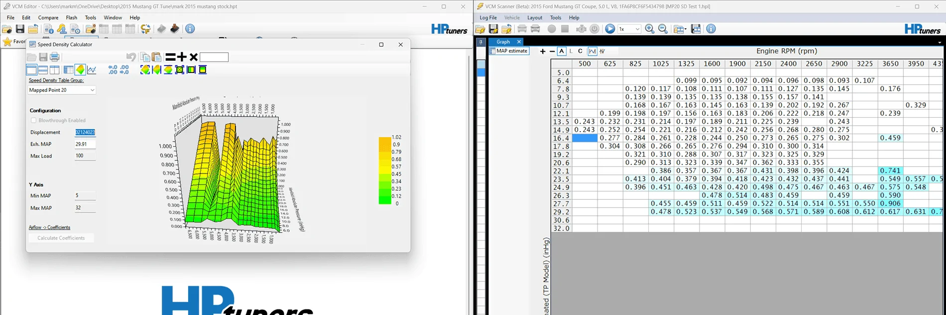
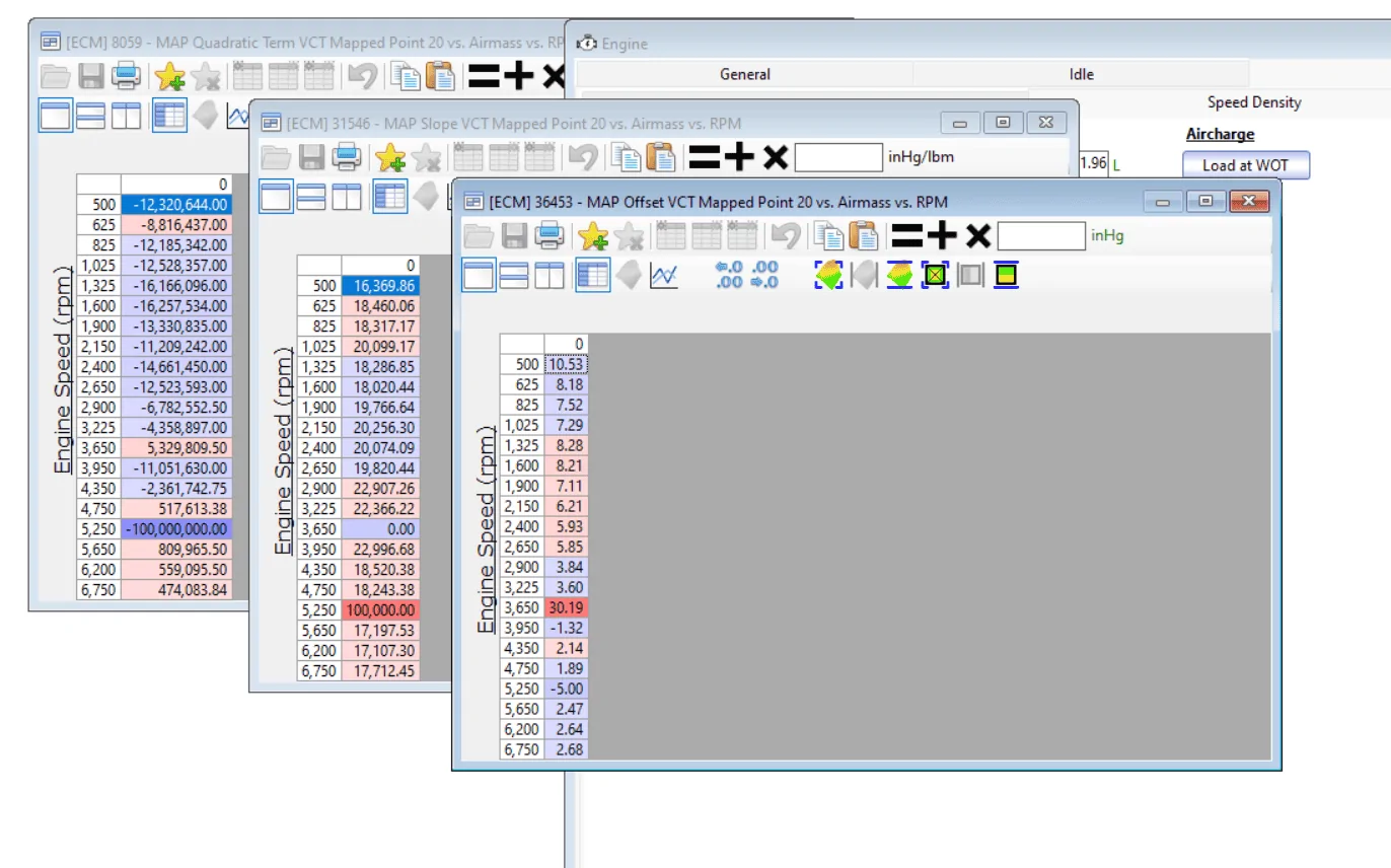
You have it correct. I format it to the way HPT displays it.

Also here are the rpm values it uses:
500
625
1025
1325
1600
1900
2900
3225
3650
3950
4750
5250
5650
6750

Should I rescale these to 8000? And for 500 would I use rpm ranges from 500-625? Or is it like 500 rpm is 0-500, 625 rpm is 500-625, etc?

Edit: I can add 6 more rpm values to expand the tables
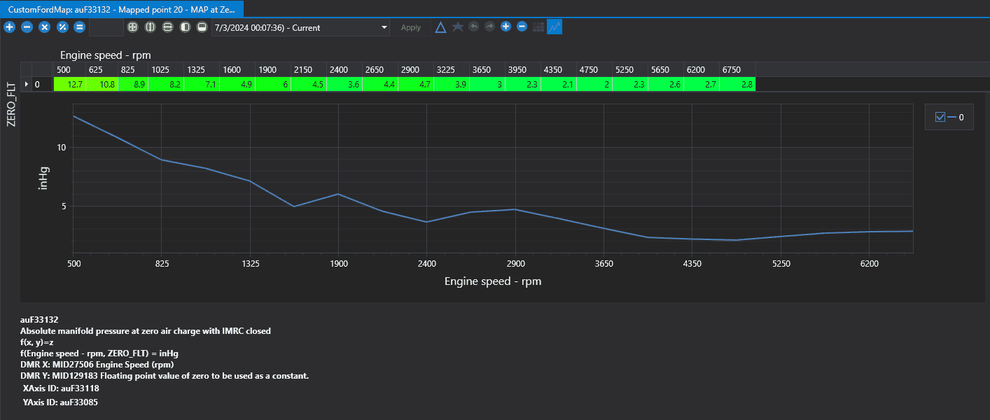
Yes now is the time to change the RPMs to what ever you want, and make it cover the RPM range you plan on using, you are going to need to tune it all anyway. Just share your tune file with the most recent changes and the logs you take on that tune file, and everyone will be kept in the loop.
Sponsored


markmurfie

Well-Known Member
Joined
Jun 6, 2015
Threads
15
Messages
1,320
Reaction score
625
Location
Hawaii
First Name
Mark
Vehicle(s)
2015 Ford Mustang GT
Should I rescale these to 8000? And for 500 would I use rpm ranges from 500-625? Or is it like 500 rpm is 0-500, 625 rpm is 500-625, etc?
500 would be used when RPMs are actually 0-500. It would then interpolate 500-625. ect.

When coming up with the coeffecients, I try to do +/-250RPM from the RPM value I have the cell populated for.

For example, 1600 I filtered out 1350-1850, but when it didnt return coeffecients I had to expand and filter 1100- 2100RPM.
 

markmurfie

Well-Known Member
Joined
Jun 6, 2015
Threads
15
Messages
1,320
Reaction score
625
Location
Hawaii
First Name
Mark
Vehicle(s)
2015 Ford Mustang GT
Then I always recommend putting your values into HPT editor, and just seeing what its calculator shows.

Even for MP20, its just bad. making a small 1% change to the high MAP cells and having it calculate the coefficients doesnt change from what I entered, so im pretty sure its happy with what I came up with. ECU should be happy with it too.
If you have ever tried entering load values into this calculator, you know how finicky it can get with values directly out of the scanner.

Screenshot 2024-07-02 221359.png
 
Last edited:

markmurfie

Well-Known Member
Joined
Jun 6, 2015
Threads
15
Messages
1,320
Reaction score
625
Location
Hawaii
First Name
Mark
Vehicle(s)
2015 Ford Mustang GT
Example of HPTs calculator being finicky straight from the log I got my coefficients from.

Airload values against estimated MAP form TB model copied into the calculator.
Air load copied into calculator.png


What it spits out when you ask it to calculate.

calculate coefficients from log load values.png


Coefficients from HPT calculator.png


It may be better if I just copied the sub 3000RPM range where the data is filled out, but it doesnt change it nearly enough.
People hate tring to figure this thing out.
 
Last edited:

Pistol_91

Well-Known Member
Joined
Oct 25, 2023
Threads
12
Messages
1,382
Reaction score
1,407
Location
Clearwater
Vehicle(s)
2020 mustang GT
Example of HPTs calculator being finicky straight from the log I got my coefficients from.

Airload values against estimated MAP form TB model copied into the calculator.
Air load copied into calculator.png


What it spits out when you ask it to calculate.

calculate coefficients from log load values.png


Coefficients from HPT calculator.png


It may be better if I just copied the sub 3000RPM range where the data is filled out, but it doesnt change it nearly enough.
People hate tring to figure this thing out.
Smooth and re calculate. X50 lol
 

Sponsored

K4fxd

Well-Known Member
Joined
Apr 2, 2020
Threads
121
Messages
13,455
Reaction score
12,262
Location
NKY
First Name
Dan
Vehicle(s)
2017 gt, 2002 FXDWG, 2008 C6,
If you set the distance tables like I showed it will lock to MP5

MP's 0-13 are IMRC closed 14-26 IMRC open

This tune only uses MP 10 for everything other than idle and WOT
MP5.3.png
 

Pistol_91

Well-Known Member
Joined
Oct 25, 2023
Threads
12
Messages
1,382
Reaction score
1,407
Location
Clearwater
Vehicle(s)
2020 mustang GT
Which brings me to wonder why are you trying to lock on MP5 and tune it at WOT since it will never be used for WOT? Makes no sense. No power is because that MP is for a closed IMRC like K4 mentioned above.
 

K4fxd

Well-Known Member
Joined
Apr 2, 2020
Threads
121
Messages
13,455
Reaction score
12,262
Location
NKY
First Name
Dan
Vehicle(s)
2017 gt, 2002 FXDWG, 2008 C6,
Snap points and lines
MP5.4.png
 

engineermike

Well-Known Member
Joined
Jul 15, 2018
Threads
31
Messages
6,189
Reaction score
6,454
Location
La
Vehicle(s)
2018 GTPP A10
Good info and that's what i was getting at about the car not having power with MP5.
It’s not supposed to have a lot of power (torque) in MP5. That’s not why MP5 exists.

I’ll decide on a good cruise mapped point to start with. MP20 seems to be okay.
MP20 is no good for cruise because imrc are open and there is no imrc closed MP at that same location. There’s a reason I suggested MP7 or 9.

Im not sure why the mapped points aren't sticking to 100% (or very close)…I know for MP5/17 log the car was probably hitting some timmed/temp vct degree limit as it seemed to change as the car ran longer. Those are easy to move out of the way.
It probably is one of the phase limit tables you’re hitting but if you aren’t going to use MP5 then the point is moot. The more important point is that you understand why you’re isolating mapped points and why it’s important the weighting needs to be near 100% before you start tuning.

Should I manually disable other mapped points?
NOOOO!!! This will force mapped point data to be used even if the cam positions don’t match the mapped point. This is the opposite of what you’re trying to accomplish. The actual cam angles need to be the same as the mapped point you’re trying to tune!
 

engineermike

Well-Known Member
Joined
Jul 15, 2018
Threads
31
Messages
6,189
Reaction score
6,454
Location
La
Vehicle(s)
2018 GTPP A10
I don't know how the blending works with numbers like 8.82 (4000rpm, 0.45 load). Does it blend between the line distance values of 20 and 21? Idk.
That is correct. This is how you would command a cam angle between two non-sequential mapped points. Like if you wanted to command a location that lies between mapped point 5 and 7, you couldn’t just command 6 because 6 might not be located between 5 and 7. But manipulating the index arrays would allow you do command something between 5 and 7.
 

Sponsored

engineermike

Well-Known Member
Joined
Jul 15, 2018
Threads
31
Messages
6,189
Reaction score
6,454
Location
La
Vehicle(s)
2018 GTPP A10
Also here are the rpm values it uses:
500

6750

Should I rescale these to 8000? And for 500 would I use rpm ranges from 500-625? Or is it like 500 rpm is 0-500, 625 rpm is 500-625, etc?

Edit: I can add 6 more rpm values to expand the tables
You want them to match the axis scales that you’re tuning. Each row in the table corresponds to a specific rpm, so the coefficients should be for that specific rpm. This is why I suggested some time back to vary the load at constant rpm, as best as you can. I’ve tried doing histograms and it has its pitfalls because the data is so dynamic. It works best if you can hold rpm constant at an existing row value and vary the pedal. You really only need 3-4 good steady-ish state loads for each rpm to gather the data needed for a pretty decent curve fit.
 

engineermike

Well-Known Member
Joined
Jul 15, 2018
Threads
31
Messages
6,189
Reaction score
6,454
Location
La
Vehicle(s)
2018 GTPP A10
Been thinking mapped point layout and considering cam specs.

Exhaust: The comp stage 3 cams add 26 deg of duration to the EVO side of the lobe and then go on to advance it and additional 4 deg. This means EVO happens a total of 30 degrees (!!!) earlier than stock and it has 4 deg less in the overlap EVC region. EVO is more influential to performance than EVC. Too early and you lose part of your power stroke, too late and you don’t have time to blow down the high cylinder pressure before starting the exhaust stroke. The EVC side is during overlap and can have some benefits of drawing the pressure negative to help pull in intake charge. That said, with an EVO that early, you’d want to generally run the exhaust cam more retarded than stock just to prevent too early an EVO, but to get the same EVO as stock you would need to add a whopping 30 to all the exhaust cam angles commanded, so like at wot your exhaust angle would be like 45 instead of the traditional 15. I saw where Lund was commanding 25 so that makes some sense to me now, but I think it would be worth exploring 35 for OP EVC. Another clue is that if you want to keep the same ECL as stock and allow the duration to be added equally to EVO and EVC then in OP you’d add 17 to the stock values, which puts you at 32-37, so we arrive back at 35. For cruise, the issue of delaying EVO becomes more important since they moved EVO so far advanced. I’d use 50 at cruise. For idle, min overlap governs so it’s 0.

Intake: Comp added 15 to IVC and 9 to the IVO side. IVC is more influential to performance. If you wanted to retain the same IVC as stock, you would subtract 15 from all the IVO values, so at cruise you’d be at 25 and it would stop retarding at 0 at wot.

That said, this is how I would arrange the mapped points:

MP0, (0/0, imrc closed): Startup only. Set the ER mapped points to MP1 to get it out of MP0 asap. If it starts fine, then this point shouldn’t need much calibration.

MP1, (20/0, imrc closed): Idle only. Copy torque, sd, and spark data from your current 20/0 mapped point into MP1 then proceed with tuning the sd model in the low speed and load region.

MP2, (25/50, imrc closed): Cruise. Set it up to use this one from very low speeds and loads up to about .6 load with 100% weight. I believe there is a mapped point already at 30/50 that you can steal the starting point data from. This one will require the most calibration as you will use it most of the time at a broader span of speeds and loads. Tune the sd model first.

MP3, (5/35, imrc closed): Transition to OP before imrc opens. Calibrate and use this one from .6-.8 load. Again, steal the starting point data from an existing nearby point.

MP4, (5/35, imrc open): Transition to OP after imrc opens. Calibrate and use this one also from .6 to .8 load. Set up the imrc to open at .7 load so the entire imrc transition is done at this cam timing.

MP5, (-20/35, imrc open): This is only used at wot in the midrange so only needs calibration from .8 to 1.1 load. I believe there is an existing mapped point there you can steal data from.

Set it up to switch to OP at .8 load and 0% throttle. This is an AND logic statement so this will ensure it switches to OP any time load is over .8. OP cam timing would he commanded on a snap line between -20/35 and 5/35.

Add snap lines:
0-1
1-2
1-3
2-3
3-4
4-5

Of course, once this is all set up, you’d still need to isolate and calibrate each point before scheduling them as you normally would.
 

K4fxd

Well-Known Member
Joined
Apr 2, 2020
Threads
121
Messages
13,455
Reaction score
12,262
Location
NKY
First Name
Dan
Vehicle(s)
2017 gt, 2002 FXDWG, 2008 C6,
Why have a 1-3 snap line?
 

engineermike

Well-Known Member
Joined
Jul 15, 2018
Threads
31
Messages
6,189
Reaction score
6,454
Location
La
Vehicle(s)
2018 GTPP A10
Why have a 1-3 snap line?
Probably not necessary but won’t hurt anything. The though is if it tries to go from optimum stability straight to optimum power then it would go from 1 to 3.
 

markmurfie

Well-Known Member
Joined
Jun 6, 2015
Threads
15
Messages
1,320
Reaction score
625
Location
Hawaii
First Name
Mark
Vehicle(s)
2015 Ford Mustang GT
Besides the fact no one has mention what to do with the IMRC distance axis's in any of these proposed changes, or in an attempt to hold them open or closed longer for tuning purposes, this reduced number of mapped points strategy doesn't cover IMRC opening and closing very well. This is why Ford doubled the mapped points in 2015+ as they couldn't just blend a few cam positions at closed IMRC to a few with open IMRC and have it come out well. The cams will have to be in motion while IMRC is in motion opening or closing, thats going to be very tough to calibrate for, if its not impossible. You want mapped points that contain the same cam angles, but the difference is IMRC open/ closed.
OR just lock them open if you want it simple.

This is what you are basically proposing. I dont think this will work out well.

Screenshot 2024-07-04 155959.png


I would expand Mikes suggestion for MP 0,1,2 and make the same angles with IMRC open 3,4,5. 6 would be an IMRC open mapped point only, but an additional one could expand the IMRC closed plane if desired. I dont think its needed tho. Them take his MP 5 angles and make it MP7, also add MP 8 (-20,0) for cam movement at OP. Its going to limited in OP mode if it doesnt have a defined point to blend with out there. Thats a total of 9 mapped points. Thats as simple as I would go with it or just reduce how much you want the cams to move around and independant of one another. I think thats the point of putting larger cams in any way to reduce how much the VCT needs to move them around.

What Mikes suggestion covers based on IMRC open(green line) vs closed (blue plane).

Mike ssuggestion.png


VS with the additional mapped points, IMRC open in the Green plane and IMRC closed in blue plane. Cams can be anywhere in the blue plane and the IMRC can open or close, and its covered. Cams can be anywhere in the green plane and its covered, including OP angles.
This would allow you to command the IMRC to open and close at what ever load you find works best. Nothing has to wait for the cams to move or vise versa, its all independant from one another.

Additional MPs simplified.png


Remeber HDFX is a kernel of weight and needs a integration domain created by the calibrated points. The absolute minimum for TI-VCT is three. Ti-VCT with IMRC is 6.

Screenshot 2024-07-04 164233.webp
Sponsored

 
Last edited:


Top