Andy13186
Well-Known Member
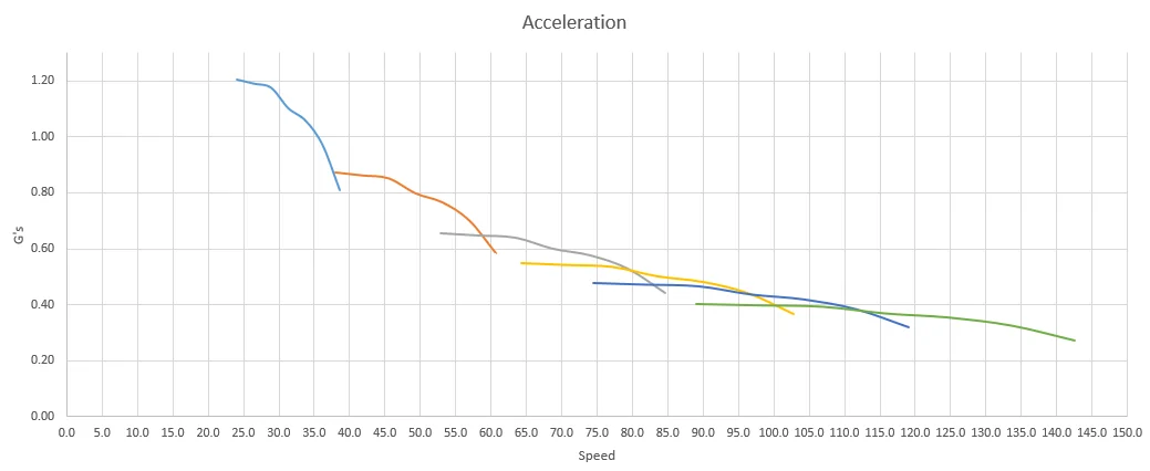
I think only the total HP, not torque, under the dyno curve between the shift points are what matters. More hp for more time means more acceleration , torque numbers dont really matter if I understand it correctly
Sponsored