Sponsored

Diff bolt bending/breakage-my take

Robottrainer

Well-Known Member
Joined
Apr 25, 2021
Threads
79
Messages
999
Reaction score
425
Location
Canada
First Name
John
Vehicle(s)
2018 Ford Escape. 2020 Jeep Cherokee. 2021 Ford Mustang GT Stage 2 Roush
Hi All,

I've been reading with interest and dismay regarding the number of diff bolt and bushing failures reported on this forum. In the grand scheme of things its probably rare, but when it happens to you and the amount of carnage it causes, it is a concern. I am about to embark on swapping out the bolts and installing either the Steeda or BMR bushing lock outs.

A little back ground. I am a Mechanical Technologist by trade. I do have a bit of structural engineering background. My brother is a Professional Mechanical Enegineer. I was discussing this situation with him at length yesterday and we came up with a take on the whole matter.

The design of this seems bent on a intents. Cost, ease of assembly and driver comfort. Its a compromise. For the average joe or joanne, they will drive for years and never give this a thought or have a problem. A combination of the cars age and the driving style will ultimately decide when the system will give up the ghost. The manufacturer hopes that its after the warranty expires.

We both looked at these failures. Both of us are convinced it isnt a shear failure but a bending/torsional failure compounded by work hardening. Shear infers that one part of the bolt is stationary (bushing) and the other is moving (diff). This would be true for a solid bushing. In most cases we are dealing with the rubber bushing and sometimes bushing lock out. No matter what you stick in the bushing, there will always be some movement, unless its solid. If it moves, together, the shear is is almost nil.

In OEM form, the bolts clamp the diff to the bushings. The more clamping force the more friction so everything moves together. What happens if the bushing hits its movement limit? The bolt could shear at that point. If you get bellow that point and you hit the yield strength of the bolt (more to do with the grade of the bolts), it will start to bend. Bend it enough times and it will break. Just like when you bend a wire repeatedly over and over. So how do you stop it.

Kelltracs solution seems to be on the right track. It relies more on massive size size (5/8" bolts on the shank) than it does bolt grade, although they do use ASTM 574 bolts. You need more force to get to the yield strength the bigger something is. You could use a hardware grad bolt if it were 2" in diameter. The only draw back I see with this is the reduced material in the front boss and rear cover after drilling. These parts were never designed for holes this big. Extreme loads, will find the weakest link. You could see a spat of broken bosses/lugs with this eventually. Time will tell.

Next option, probably more for the less intense users is the Steeda 555-4051. Their approach is different. Maybe not as effective as Kelltracs, but should work for 90% of us. This uses a fully threaded 4140 M14 bolt and nut at the front and a longer threaded bolt in the read. Having a fully threaded front bolt makes the bolt and threaded bushing insert "one piece". The nut then clapms the front diff boss to the bushing. The clamping force is lower than Kelltracs at 129 lb ft. This sytem relies on the higher yield strength and toughness of 4140 heat treated material

Another issue is slop. Too much clearance between the bolt and the bushing. Kelltrac solves this by drilling everything out to 5/8". The bolts have a closer fit. With the Steeda kit you will need to have an insert for the rear bushings. The front bushing is taken care of by having a fully threaded bolt in the insert. Probably wouldnt hurt to have an insert in the diff boss, but I havent seen any info on what size the oem hole is. Slop in these areas area killer.

Anyhow, opinion are those of the author.
Sponsored
 

WD Pro

Well-Known Member
Joined
Jan 18, 2018
Threads
132
Messages
6,798
Reaction score
13,625
Location
United Kingdom
Vehicle(s)
Lime GT
Vehicle Showcase
1
I’m reasonably confident that the cause of my breakage was poor manufacturing, and then assembly not picking it up (or turning a blind eye) :frown:

WD :like:
 

shogun32

Well-Known Member
Joined
Feb 8, 2019
Threads
92
Messages
16,223
Reaction score
14,019
Location
Northern VA
First Name
Matt
Vehicle(s)
'19 GT/PP, '23 GB Mach1, '12 Audi S5 (v8+6mt)
Vehicle Showcase
2
either the Steeda or BMR bushing lock outs.
Go whiteline for pucks. Or steedas copy of the whitline total replacement system.

My GT has WL cut out and replace at the IRS and diff. There is a low grade growl from the trans tunnel which is exacerbated by the trans front insert. Think of it as tire noise but less obnoxious.

All this rubber and bad mechanical engineering is a direct result of someone confusing a mustang design brief with one for an Accord.

Anyone want to take a bet the S650 rear is still drilled 16mm for a 14mm fastener? Ford engineering quality and attention to detail at its finest.
 
Last edited:
OP
OP
Robottrainer

Robottrainer

Well-Known Member
Joined
Apr 25, 2021
Threads
79
Messages
999
Reaction score
425
Location
Canada
First Name
John
Vehicle(s)
2018 Ford Escape. 2020 Jeep Cherokee. 2021 Ford Mustang GT Stage 2 Roush
I’m reasonably confident that the cause of my breakage was poor manufacturing, and then assembly not picking it up (or turning a blind eye) :frown:

WD :like:
That's another problem
 

80FoxCoupe

Well-Known Member
Joined
Mar 28, 2018
Threads
51
Messages
5,501
Reaction score
6,258
Location
Cincy, OH
Vehicle(s)
16 GT, 80 Fox
My car is setup for drag racing and is full weight. Im at the track alot and make tons of passes each year. At 680whp, no issues with stock bolts. At 900whp, no issues with bmr lockouts, sleeves and oem sized bolt upgrade. At 1200+whp, no issues with keltrac big bolts and keltrac/SuperPro diff bushings. Your results may vary.
 

Sponsored

OP
OP
Robottrainer

Robottrainer

Well-Known Member
Joined
Apr 25, 2021
Threads
79
Messages
999
Reaction score
425
Location
Canada
First Name
John
Vehicle(s)
2018 Ford Escape. 2020 Jeep Cherokee. 2021 Ford Mustang GT Stage 2 Roush
Go whiteline for pucks. Or steedas copy of the whitline total replacement system.

My GT has WL cut out and replace at the IRS and diff. There is a low grade growl from the trans tunnel which is exacerbated by the trans front insert. Think of it as tire noise but less obnoxious.

All this rubber and bad mechanical engineering is a direct result of someone confusing a mustang design brief with one for an Accord.

Anyone want to take a bet the S650 rear is still drilled 16mm for a 14mm fastener? Ford engineering quality and attention to detail at its finest.
If they can save a buck, get past the warranty period and satisfy 90% of the buying public its good enough
 

WD Pro

Well-Known Member
Joined
Jan 18, 2018
Threads
132
Messages
6,798
Reaction score
13,625
Location
United Kingdom
Vehicle(s)
Lime GT
Vehicle Showcase
1
That's another problem
Here is what I posted about it :

I acquired a diff cover (note to cover my arse : of a cover that I found on ebay with an identical failure mode to mine i.e. nothing to do with my warranty claim).

A little investigation seems to back up the theory I had behind my failure i.e. poor assembly rather than abuse, but I haven't sorted all the pictures out yet so I will save that for another post.

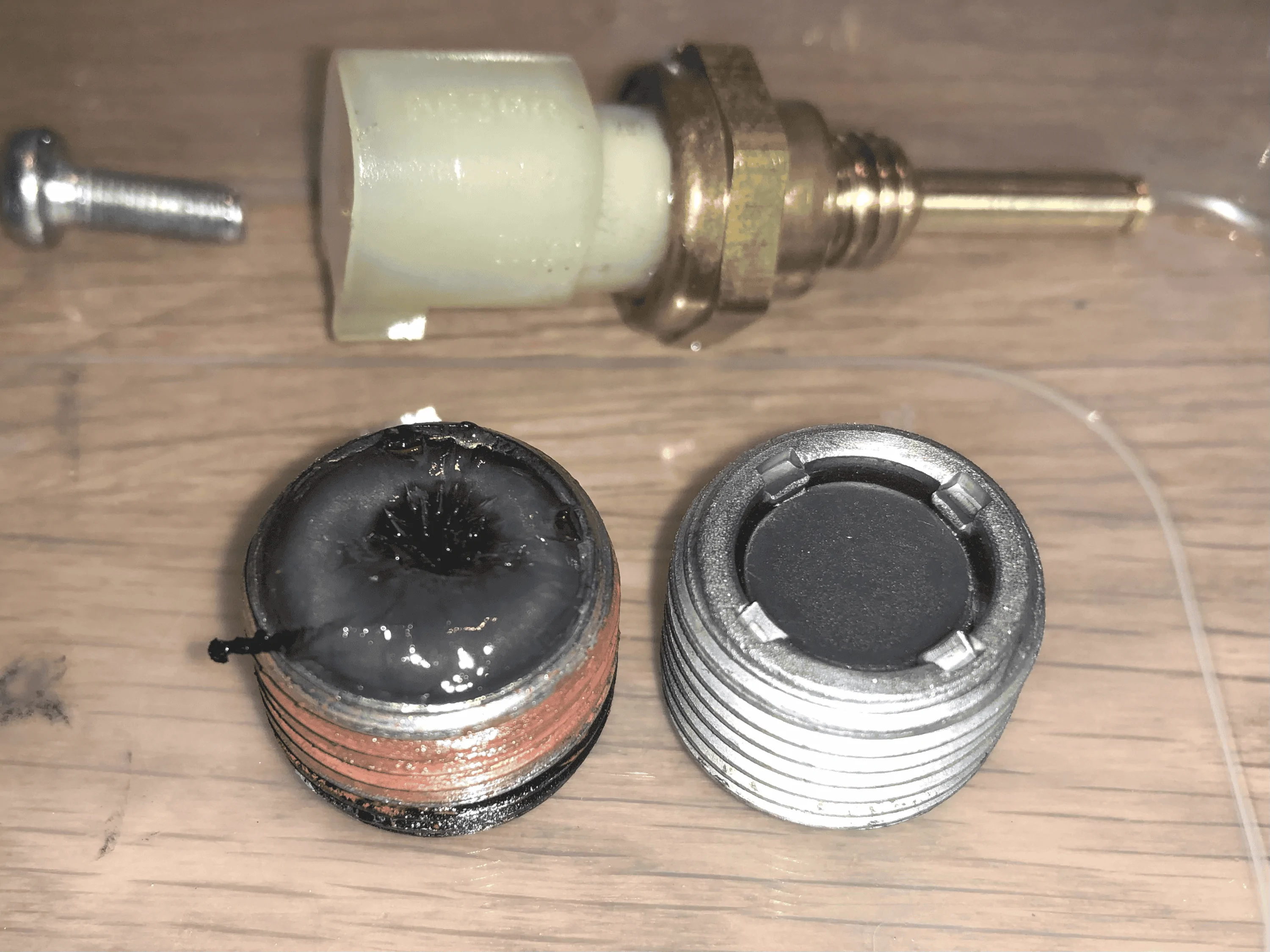
Here's the magnets though (at the same mileage as my failure -circa 2.5K of reasonably enthusiastic road miles) :

1696584353781.webp


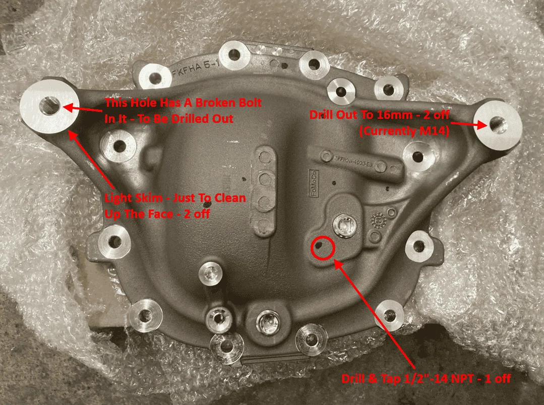
The old cover is going to get cleaned up and prepped for the M16 bolt conversion :

image.PNG


The machining work will hopefully take place over the Christmas period, and it will include the hole required to run a cooler - but initially that will just be plugged :

IMG_0940.jpg


WD :like:
Following on from the above, here are some more pictures, and my theory on the failure mode.

The witness in the euro underseal is the first thing that drew my attention (left mount / missing bolt head) :

1703751816229.jpeg


A closer look, note the vertical wear pattern from the bolt head :

1703751857433.jpeg


On the picture above, also note the wear on the bush from the bolt shank (bottom edge, closest to the camera).

Here are some more photos of the bush wear from the shank of the bolt :

1703751903353.jpeg


1703751943707.jpeg


1703751981433.jpeg


Now the Ford tech said that the remaining right hand bolt was really tight to remove, and he feared breaking that during the strip down.

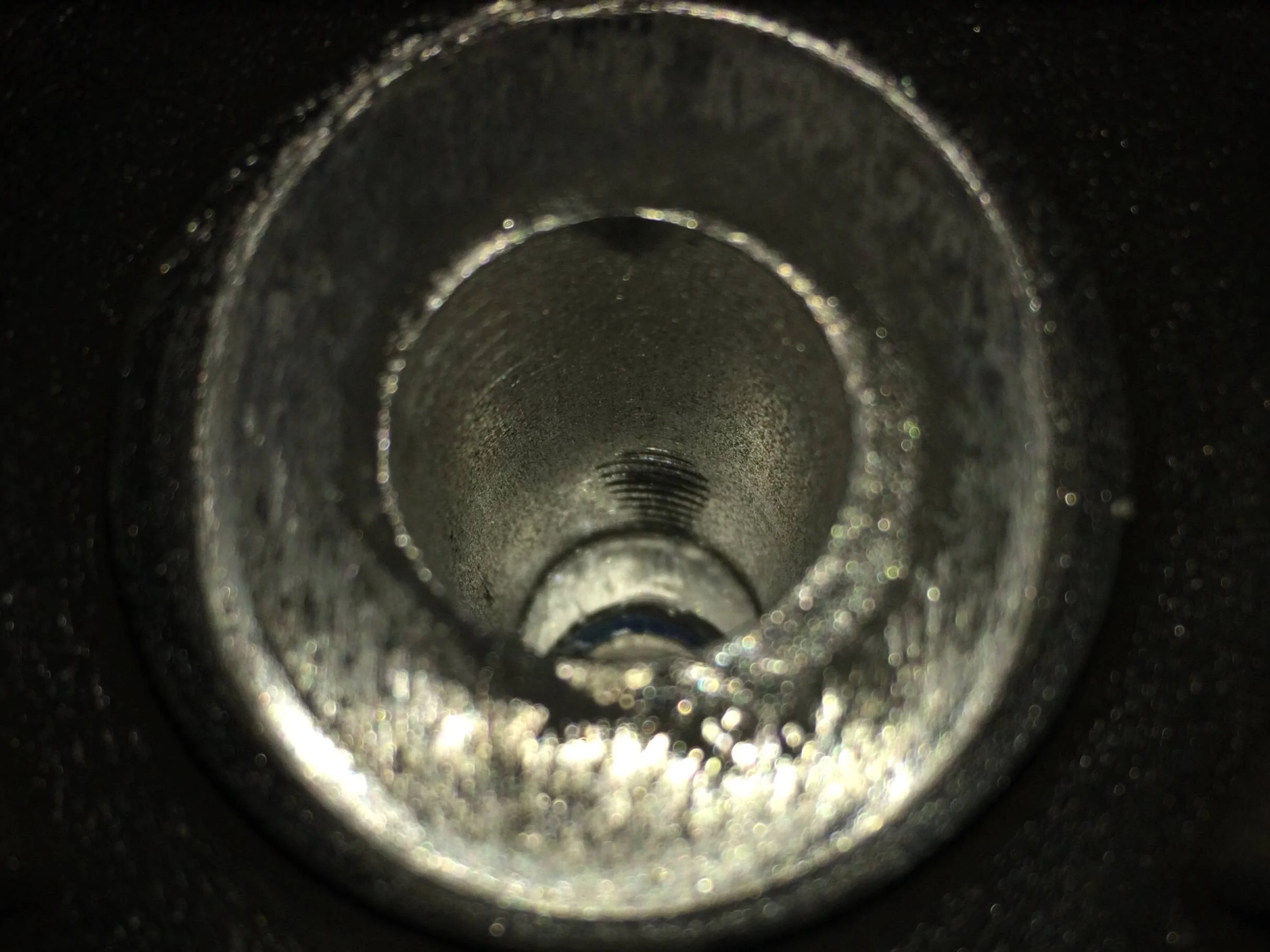
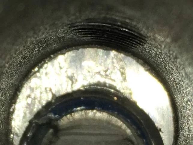
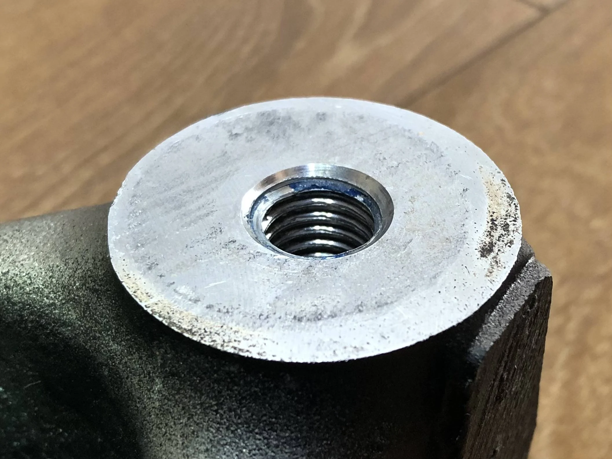
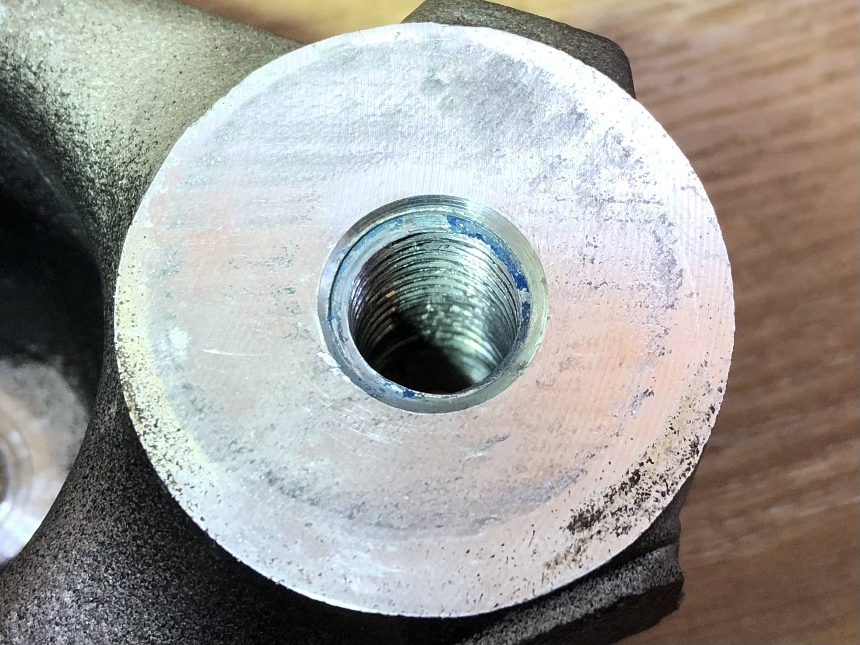
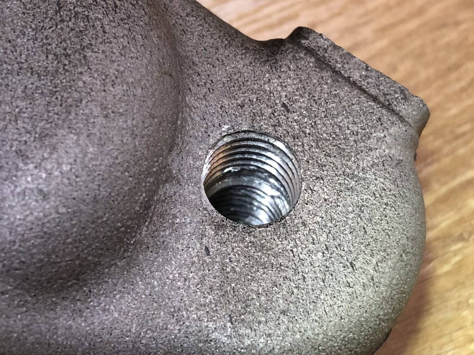
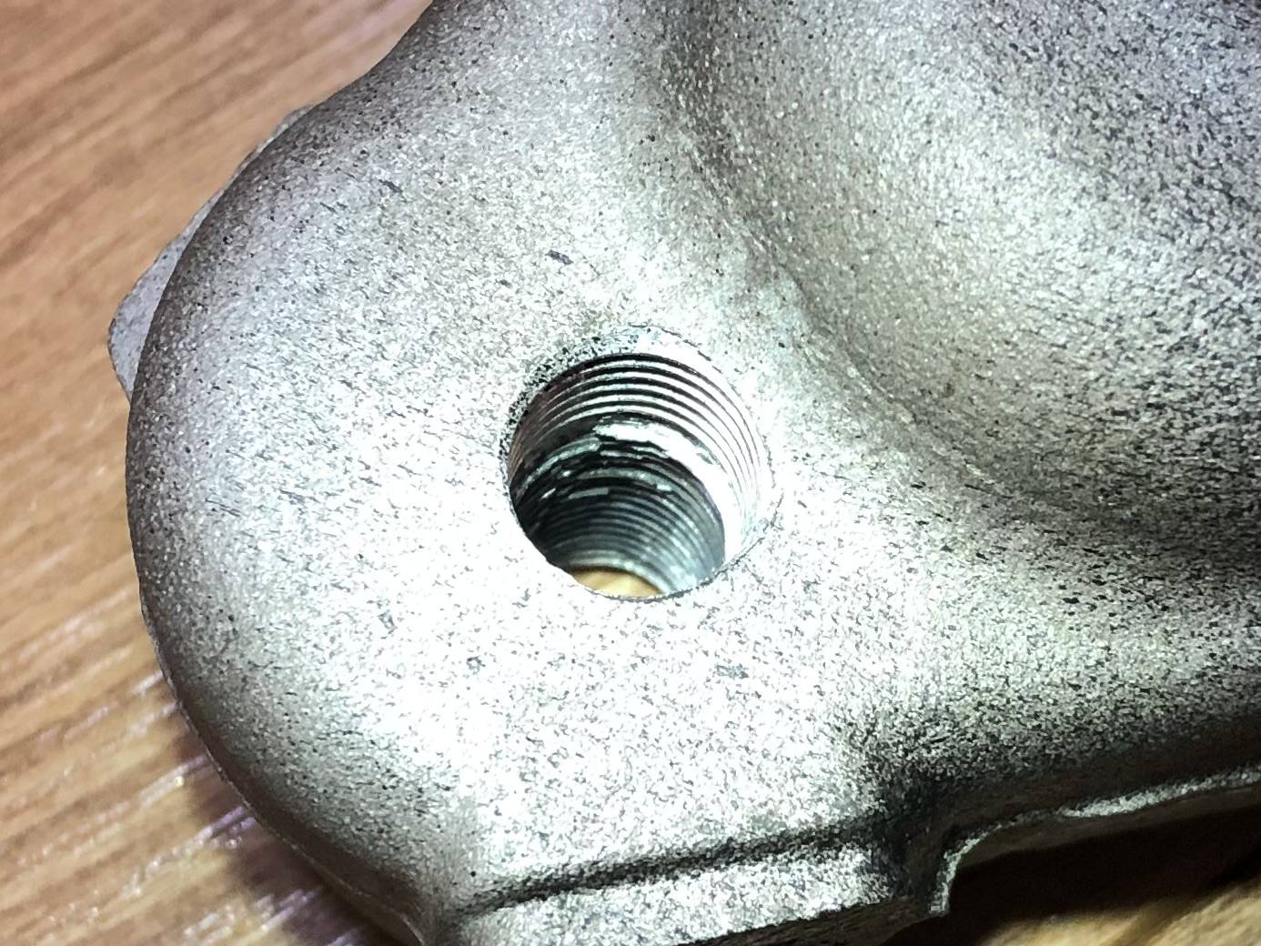
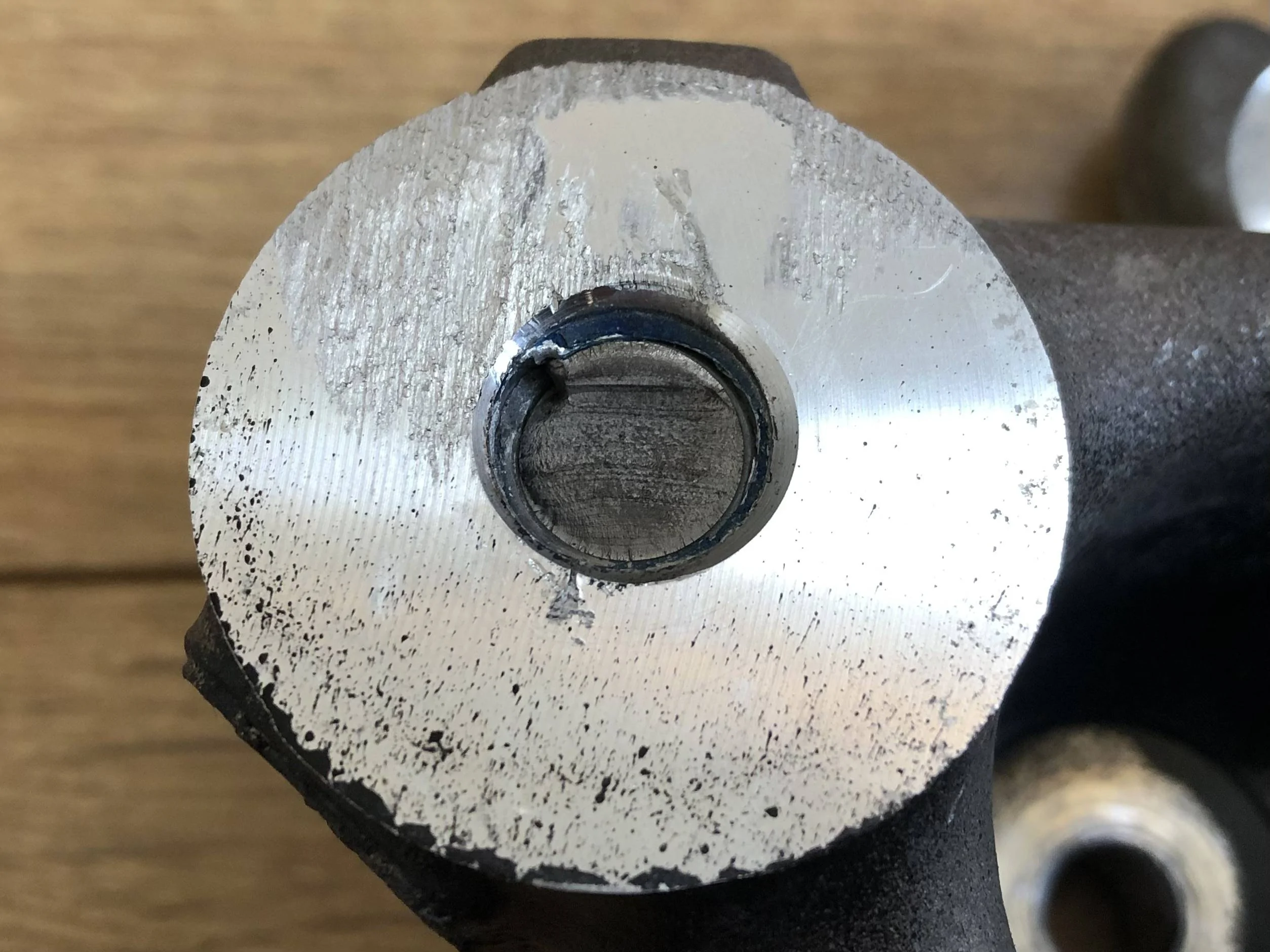
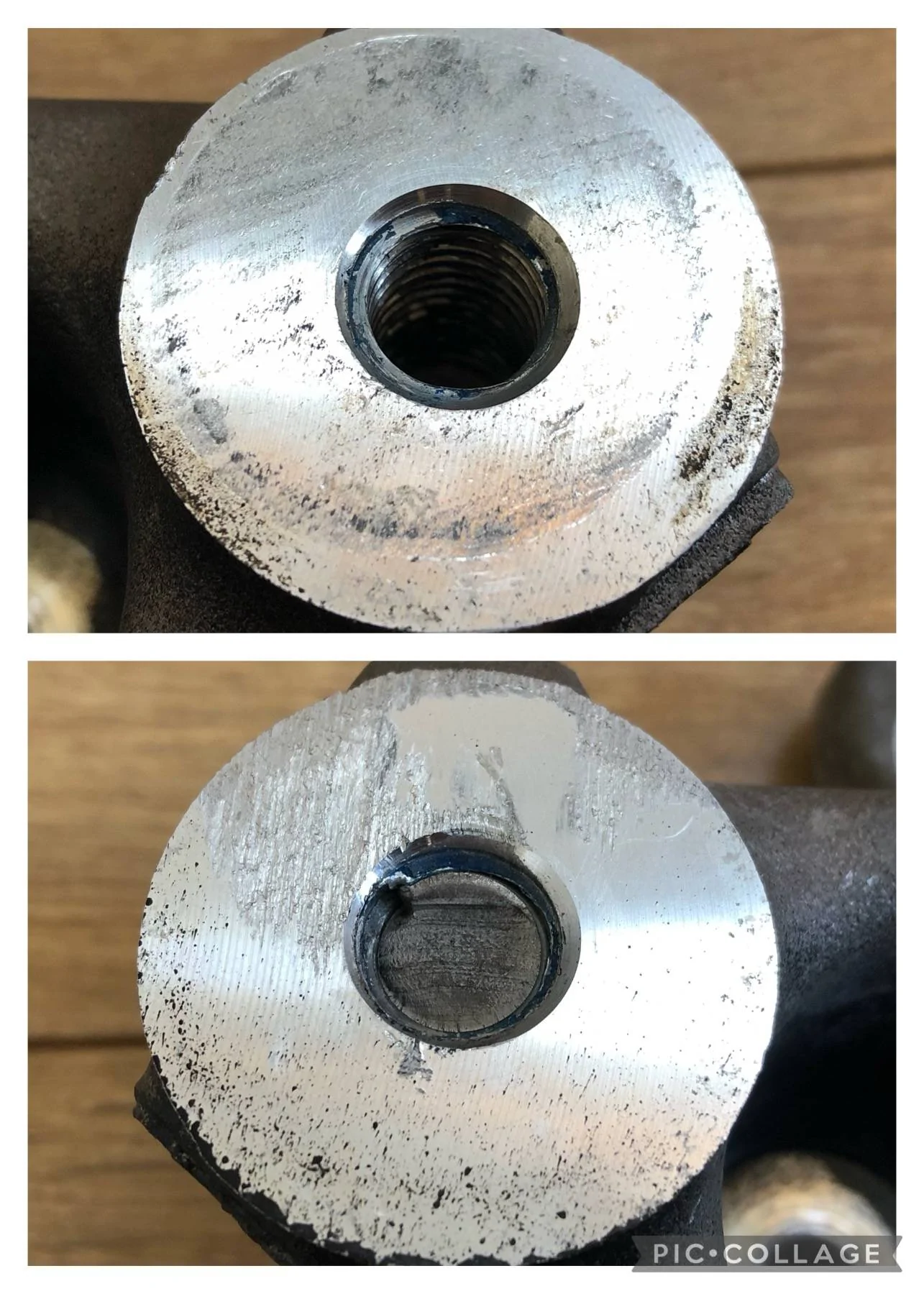
This is the right hand thread in the diff cover, remembering that this thread has only had a bolt inserted and removed once, it clearly has a damaged / cross threaded thread form :

1703752045579.jpeg


1703752073769.jpeg


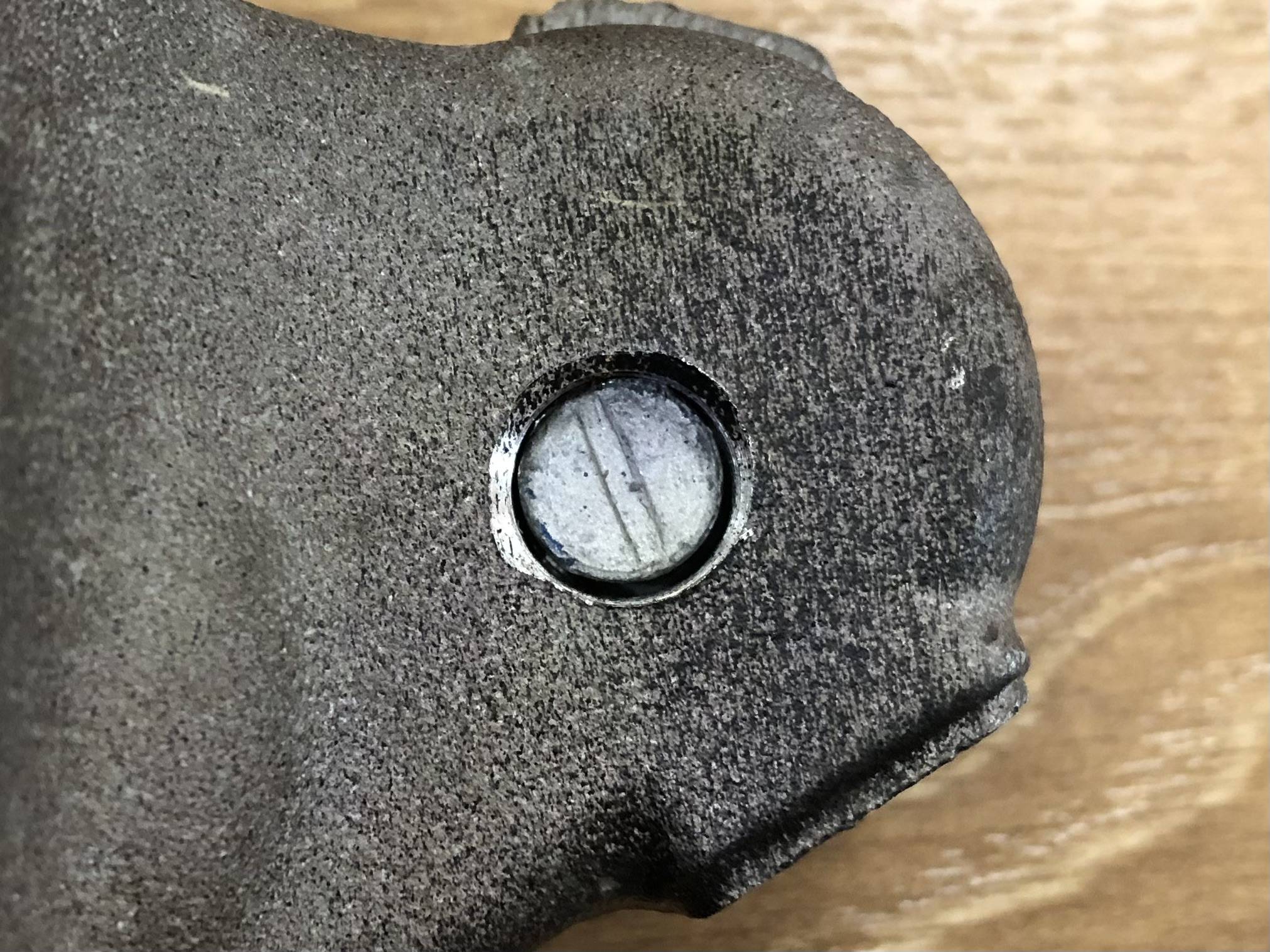
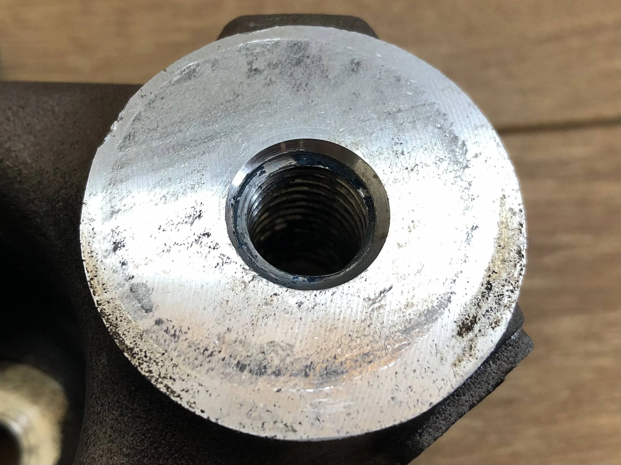
Which is really difficult to photo, but very apparent from the other side of the mount :

1703752110191.jpeg


1703752140878.jpeg


What I can’t capture on photo, is that the first 2/3rds of the thread, appear to run at a slightly different angle to the last 1/3rd.

Again not easy to capture on a photo, but the broken bolt looks offset in the bore, almost like it’s really being driven skewed into one side of the thread :

1703752169895.jpeg


To me, these next two are the most telling photos …

Here is the mounting face on the ā€˜good’ side (even though we know this side still had a suspect thread), note the witness mark where it’s been clamped tight against the subframe bush :

1703752210853.jpeg


Now compare that to the failed side, that has zero witness to being clamped, AND even has euro underseal overspray on the mating face, even though the underseal is applied after assembly :

1703752242557.jpeg


It’s very obvious on this comparison :

1703752325515.jpeg


So my unprofessional armchair conclusion :
  • Neither right or left threads were good from the factory.
  • The right thread allowed for some clamping force to the mating faces.
  • The left thread provided no clamping force to the mating faces.
  • No clamping force = all the stress through the shank of the bolt = bolt failure due to fatigue.
I’m open to, and interested in other opinions / theories, so please feel free to chime in with any alternatives :like:

WD :like:
WD :like:
 
OP
OP
Robottrainer

Robottrainer

Well-Known Member
Joined
Apr 25, 2021
Threads
79
Messages
999
Reaction score
425
Location
Canada
First Name
John
Vehicle(s)
2018 Ford Escape. 2020 Jeep Cherokee. 2021 Ford Mustang GT Stage 2 Roush
Here is what I posted about it :


WD :like:
Wow! It appears it may have gotten cross threaded from whoever assembled the cradle. With everything being automated with torque monitoring assembly, a cross threaded bolts would hit the number before enough torque was generated to clamp everything in place.
 

WD Pro

Well-Known Member
Joined
Jan 18, 2018
Threads
132
Messages
6,798
Reaction score
13,625
Location
United Kingdom
Vehicle(s)
Lime GT
Vehicle Showcase
1
With everything being automated with torque monitoring assembly, a cross threaded bolts would hit the number before enough torque was generated to clamp everything in place.
Yes, but what about the guns that count the number of turns before the number is achieved ?

When mine first broke I hit the search function and found another thread with a broken bolt. The original poster was advised it was an easy fix - just remove the broken bit of stud and reassemble with new hardware. Yet he couldn’t remove the broken bit, and he replaced the rear cover to fix it.

I got the feeling that people thought he hadn’t tried hard enough or didn’t have the right skills to remove the broken stud, but now I wonder if my experience whilst still rare, wasn’t a one off ?

Whilst I can’t defend Fords design of these components, I do wonder if ā€˜incorrect torque’ is the biggest killer, but ā€˜bad design’ steals most / all of the limelight ?

What else could explain the seemingly huge difference in people’s experience of bolt failure (with regards to power and usage), especially when you read comments like that posted by @80FoxCoupe ?

My car is setup for drag racing and is full weight. Im at the track alot and make tons of passes each year. At 680whp, no issues with stock bolts. At 900whp, no issues with bmr lockouts, sleeves and oem sized bolt upgrade. At 1200+whp, no issues with keltrac big bolts and keltrac/SuperPro diff bushings. Your results may vary.
WD :like:
 
OP
OP
Robottrainer

Robottrainer

Well-Known Member
Joined
Apr 25, 2021
Threads
79
Messages
999
Reaction score
425
Location
Canada
First Name
John
Vehicle(s)
2018 Ford Escape. 2020 Jeep Cherokee. 2021 Ford Mustang GT Stage 2 Roush
Yes, but what about the guns that count the number of turns before the number is achieved ?

When mine first broke I hit the search function and found another thread with a broken bolt. The original poster was advised it was an easy fix - just remove the broken bit of stud and reassemble with new hardware. Yet he couldn’t remove the broken bit, and he replaced the rear cover to fix it.

I got the feeling that people thought he hadn’t tried hard enough or didn’t have the right skills to remove the broken stud, but now I wonder if my experience whilst still rare, wasn’t a one off ?

Whilst I can’t defend Fords design of these components, I do wonder if ā€˜incorrect torque’ is the biggest killer, but ā€˜bad design’ steals most / all of the limelight ?

What else could explain the seemingly huge difference in people’s experience of bolt failure (with regards to power and usage), especially when you read comments like that posted by @80FoxCoupe ?


WD :like:
I know some of the robotic automation I have done with seat assembly stations the bolt runners were set to torque. They didn't consider number of turns. Typically they spin counter clockwise first to line up the bolt, then clockwise.

This isn't to say in some process the bolt runners don't do both. With a cross threat situation, the torque will hit prematurely and the bolt runner stops. There is a plus minus % to that torque point. In this situation the count won't be achieved, it should stop and alarm out.

This has so many points of failure. The cnc tooling might have threaded the cover incorrectly, however, that's more unlikely since you would have a pile of failures within a batch. Same if the bolts were defective, whether it be the threads, or the tempering process of the bolts causing the them to stretch to yield pre maturely.

Suffices to to say that something most likely went wrong in the process to lead to this situation. Probably and intermittent recurring problem. And it's the luck of the draw who gets the short straw.
 

Sponsored

WD Pro

Well-Known Member
Joined
Jan 18, 2018
Threads
132
Messages
6,798
Reaction score
13,625
Location
United Kingdom
Vehicle(s)
Lime GT
Vehicle Showcase
1
This isn't to say in some process the bolt runners don't do both. With a cross threat situation, the torque will hit prematurely and the bolt runner stops. There is a plus minus % to that torque point. In this situation the count won't be achieved, it should stop and alarm out.
Yeah I have seen both functions on front suspension assembly at JLR (maybe 25 years ago ?).

At work, on more simpler assemblies, we have some electric guns that don’t count turns, but they measure the torque as it’s screwing down. If it too much, it knows it’s cross threaded, stops, and alarms.

At one of our other facilities, they also count turns (but I guess there must be a tolerance on that to allow for initial thread engagement). Anything wrong with the torquing process or number of torques on the full assembly = no QC sticker to put on works order. No sticker on works order = no QC sign off (without a full manual check from the inspector).

We are making electrical connections, where a bad connection can lead to a ā€˜thermal incident’ (as we prefer to call them …).

WD :like:
 

bankyf

Well-Known Member
Joined
Dec 13, 2020
Threads
70
Messages
860
Reaction score
554
Location
Fredericksburg, Virginia
Vehicle(s)
2022 GT500 CFTP
Wow! It appears it may have gotten cross threaded from whoever assembled the cradle. With everything being automated with torque monitoring assembly, a cross threaded bolts would hit the number before enough torque was generated to clamp everything in place.
Nothing would surprise me. My right rear brake line connection from the body to the hose was cross threaded from the factory. Seems like a pretty critical component for a mistake like that.
 

shogun32

Well-Known Member
Joined
Feb 8, 2019
Threads
92
Messages
16,223
Reaction score
14,019
Location
Northern VA
First Name
Matt
Vehicle(s)
'19 GT/PP, '23 GB Mach1, '12 Audi S5 (v8+6mt)
Vehicle Showcase
2
can lead to a ā€˜thermal incident’
Just call them Teslas. The saying will catch on quickly.

The bus bar didn't close properly and went full Tesla.

Why is the UPS smoking? One of the batteries did a Tesla.
Sponsored


Top