HappySquirrel
W85 Whale Oil Tune
- Joined
- May 28, 2015
- Threads
- 14
- Messages
- 324
- Reaction score
- 120
- Location
- Las Vegas, NV
- First Name
- Richard
- Vehicle(s)
- 2016 Mustang EB PP CO, 97 Pathfinder 4x4
- Vehicle Showcase
- 1
- Thread starter
- #1
Hey everyone, I’m writing a guide for my Rockford Fosgate Punch 12 powered subwoofer installation. There seems to be lots of information scattered through this forum but I have yet to see a comprehensive guide that covers all the power, ground, and speaker connections with pictures in one place. I hope this helps someone.
For reference, my car has the 9-speaker system that comes standard with the premium package (no subwoofer). I also ran speaker-level inputs from my rear deck speakers to the powered sub for signal. I ran the power cable from the battery and through the grommet on the passenger side (requires removing right-front tire & plastic fender cover). I used a 4AWG amp wiring kit (probably overkill). Although this guide covers my Rockford powered sub, the install should be mostly the same for other powered subs (and even separate amps & subs) as long as they can accept speaker inputs.
Before I begin, I want to say thanks to forum members Edwin, mikes2017gt, Heinoceros, and probably some others that I can’t remember for helpful information & pictures scattered throughout this forum.
I’ll break this up into three main sections: Power Wire Install, Ground Wire Install, and Signal Wire Install
Power Wire Install
1. Remove the battery cover (held in place with 3 plastic pop-rivets). Be careful not to lose the rivets.
2. Disconnect the negative battery terminal (don’t reconnect until you’re done with all the power wiring). I recommend wrapping the terminal in a towel or something to reduce the risk of it accidentally coming in contact with the battery during the install.
3. Jack up the right-front of the car and remove the right-front wheel (make sure car is safely supported on jack stands).
4. Remove right-front plastic fender liner. This will require removing a ton of plastic pop-rivets, and there are two different sizes IIRC. I suggest using a small flat-head screwdriver and a panel tool like this: https://www.amazon.com/Cal-Hawk-Doo...1509047489&sr=8-9&keywords=panel+removal+tool
5. Run your power cable through the oval holes in the right front of the car that connect the engine bay and right fender. These holes are NOT aligned, so getting the cable through is a bit tricky, especially if you’re using the large 4AWG wire like I was. I suggest wrapping a smaller piece of wire around the end of the cable and using it to snake it through both holes if you’re having trouble. Here is a picture of the cable through the top hole for reference:

Here is a picture of the bottom hole:
It might not be a bad idea to get some grommets or some other type of insulation material to put around the oval holes to prevent the power cable’s insulation from rubbing off due to friction with the sheetmetal (I need to go back and do this).
6. Run the power cable through the large wiring harness grommet that leads into the passenger side of the cabin. With some elbow grease, you can pull the large grommet back enough to slide the cable through:
EDIT: Captdistraction has a very useful observation. You can of course go through the grommet instead of around it (not sure why I didn't think to do that): "[The] firewall grommet has a "bud" you can cut off to add a wire like this to it so you don't have to unseat it from the firewall. That raised bump can be sliced with a knife and a 4awg wire should fit nicely in it."
It should pop out underneath the glove box:
7. Run the cable underneath the trim panels along the passenger side of the cabin. You DON’T need to pop off any of the trim pieces. You can pull up on the kick panel and scuff plate trim just enough to sneak it under there (even 4AWG wire). Once you get it to the rear seat, you can slide it down into the crevice between the seat and trim and it will be concealed. At this point, you should have power cable running from your engine compartment to your trunk. Make sure you have enough cable on both ends before you start cutting and crimping.
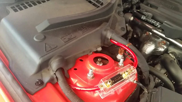
8. Lay out your fuse and hardware with the power cable near the battery. Make sure you have the right amount of cable and that you have enough clearance for the fuse (make sure it won’t hit the hood when you shut it). Measure twice, cut once!
9. Cut off part of the cable for the connection from the battery to the fuse. Strip the ends of the wire, and crimp on the proper terminals with a crimp tool (the terminals should be included with your wiring kit). Crimp then on tight and test the connection by trying to pull off the terminals. If you can pull them off by hand, it wasn’t a good crimp.
10. Strip the end of the remaining long cable and crimp on the proper terminal.
11. Attach the short wire to the positive battery terminal. I attached via the small auxiliary bolt/connection to the side of the terminal. Make sure it’s tight.
12. Attach the other end of the short cable to the fuse. Make sure it’s tight.
13. Attach the end of the long cable to the fuse. Make sure it’s tight.
14. Double check that everything is laid out like you want. Make sure the hood closes without any interference.
15. Head to the trunk. At this point, it’s probably a good idea to test fit your amp/sub in the trunk to make sure you cut the cable correctly. Cut the power cable to the proper length (don’t cut too short!).
16. Strip the end of the power cable and (if necessary) crimp on the terminal. Double check the crimp by doing a pull test. My powered sub (Rockford Punch) did not require a terminal on the amp end, so I just stripped it.
Ground Wire Install
This is the easiest part of the install. I ran my ground cable from the bracket that holds my spare tire, which I found to be easiest. This requires some sanding and purchasing a bolt from your hardware store. I’ve read that other people run the ground cable from the big bolt that secures the center of the rear seat. If you go that route, you’ll either need to find a really big terminal or wrap the wire around the bolt (I think - I didn’t go this route, so don’t quote me on that).
1. Remove everything from the spare tire area.
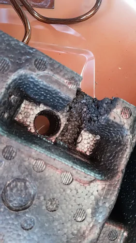
2. There are two M8 (? I think - it's been a while) threaded holes on the spare tire bracket (see picture). We will be threading into the one on the LEFT. Sand down the area around that threaded hole (see picture):

3. Run your ground cable from this area up to where your amp/sub will sit, cut the proper length (leave some slack).
4. Strip both ends. Crimp on the proper terminals (my sub didn’t require a terminal on the amp side). Do a pull test.
5. Thread an M8 bolt into the left threaded hole (the right one is where the spare tire holder threads in). You’ll need to buy this bolt from a hardware store (I think the bolt I used was 20 or 25 mm long, but I can’t remember).
6. Attach the terminal from one end of your ground cable to the bolt. Tighten the bolt down.
7. In order for the styrofoam air pump holder to clear the ground cable terminal without mashing the crap out of it, you’ll need to remove some material from it. I cut a channel out (directly over the left side where the cable will run out of) using a knife (see picture):

8. Run the other end out to where the amp will be and put everything back together.
9. At this point you can make your power connections to the amp, hook up your battery and test that your amp/sub powers up:
10. Run your power and ground cables to your amp. On my RF Punch, there is a power disconnect coupling which detaches from the amp. I detached the coupling, ran the 4AWG power and ground cables into the appropriate holes and secured the wires by turning the set screws (an allan wrench was included). Then, I popped the power disconnect coupling into the amp (it is keyed to insert only one way).
11. Carefully reconnect the negative battery terminal.
12. Turn on your car and check that the amp lights up (obviously, you won’t have sound until you’ve completed the signal wiring).
13. Replace the battery cover and reinstall the pop-rivets.
14. If you haven’t already done so, reinstall the right-front fender liner and pop rivets, reinstall the right-front wheel, lower the car and torque your lug nuts.
Signal Wires Install
I spliced off the rear deck speaker wires for my signal. You can choose other methods for signal, and if you’re planning on doing a full system and/or running a 4 or 5-channel amp for the rest of your speakers, then you should probably go ahead and find a way to run RCAs for your system. But if you’re just planning on installing a single powered sub or sub & amp, then this is probably your easiest route. I did NOT need or use a line-out converter (LOC). I did need extra speaker wire (included in my amp wiring kit) to bridge the gap between the rear speaker wiring and the subwoofer harness.
Before I begin, here is the color coding for the rear speaker wiring (thank you forum member Edwin). I suggest writing this down and leaving space next to each one to write the color code of the corresponding Amp wiring harness wires (they will not match - refer to your amp’s instructions):
EDIT: Boggus says "You can catch the same rear speaker wires from under the rear seat, easier since you won’t have to hang upside down."
2. One by one, carefully identify each of the four speaker wires that you need (see color code above) and pull it away from its paired wire as much as possible (the left & right wires for each speaker are twisted around each other).
3. Strip away part of the wire’s insulation (I think I took off about 1-inch - maybe less). I used automatic wire strippers. Whatever you use, be careful as the wires are a rather small wire gauge. Don’t cut the wire. Also, after you do the splice on one wire from each speaker wire pair, try to do the splice on the other wire from the pair farther down the line, that is not right next to the first wire’s splice (this will make it easier).
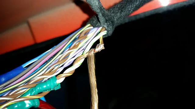
4. Splice new speaker wire onto each existing speaker wire. I soldered the new wires on (I’m sure there are other ways to go about it that don’t require soldering). I wrapped the stripped end of a new speaker wire around the exposed Ford speaker wire:
I then soldered them together (I don’t recommend tinning the new wire first, as that will make it near impossible to wrap it around the existing Ford wire):
5. Wrap the soldered connection with electrical tape:

6. If you plan on using the 12V switch wire to signal your amp to turn off and on, then repeat steps 2 through 5 for that wire. Be careful not to break the wire, as it’s thin and it is used to signal the rear camera IIRC.
7. Prepare to connect the wires to your amp’s wiring harness. I suggest thoroughly marking and documenting everything before proceeding. Write down the color codes of the Ford wires you spliced, and the colors of the added speaker wires (if they aren’t color coded then use tape or something to mark them), and the color codes of the amp harness wires. Make sure everything lines up on paper (left+ to left+, left- to left-, etc.). Double check all your connections before starting each one!
8. If necessary, cut your amp’s wiring harness. My Rockford Punch sub had RCA’s on the end of the harness, which needed to be cut off when using speaker level inputs. I cut the harness as close to the RCAs as possible, separated the wires a bit near the end, and stripped away some insulation. (If you’re using another amp/sub, you might not have a wiring harness to deal with - it might be as easy as connecting your new speaker wires right up to the amp.)
9. After you’ve triple-checked each wire pairing, connect the speaker signal wires to the amp harness wires. I soldered them and wrapped with electrical tape. I’m sure other methods would suffice.
10. Plug in your wiring harness (if applicable).
11. Turn on your car and test that the amp/sub works.
12. Tidy everything up: wrap up the black wiring cover around the original speaker wires, position/velcro your sub in place, cover your wires with wiring loom, yadda yadda.
13. If installing the RF Punch sub, attach the volume/gain remote and run it under the driver’s side trim panels just like you did with the power cable on the passenger side (this will be much easier, as the wire is smaller).
14. Adjust your gain, crossover frequency, etc. Enjoy.
For reference, my car has the 9-speaker system that comes standard with the premium package (no subwoofer). I also ran speaker-level inputs from my rear deck speakers to the powered sub for signal. I ran the power cable from the battery and through the grommet on the passenger side (requires removing right-front tire & plastic fender cover). I used a 4AWG amp wiring kit (probably overkill). Although this guide covers my Rockford powered sub, the install should be mostly the same for other powered subs (and even separate amps & subs) as long as they can accept speaker inputs.
Before I begin, I want to say thanks to forum members Edwin, mikes2017gt, Heinoceros, and probably some others that I can’t remember for helpful information & pictures scattered throughout this forum.
I’ll break this up into three main sections: Power Wire Install, Ground Wire Install, and Signal Wire Install
Power Wire Install
1. Remove the battery cover (held in place with 3 plastic pop-rivets). Be careful not to lose the rivets.
2. Disconnect the negative battery terminal (don’t reconnect until you’re done with all the power wiring). I recommend wrapping the terminal in a towel or something to reduce the risk of it accidentally coming in contact with the battery during the install.
3. Jack up the right-front of the car and remove the right-front wheel (make sure car is safely supported on jack stands).
4. Remove right-front plastic fender liner. This will require removing a ton of plastic pop-rivets, and there are two different sizes IIRC. I suggest using a small flat-head screwdriver and a panel tool like this: https://www.amazon.com/Cal-Hawk-Doo...1509047489&sr=8-9&keywords=panel+removal+tool
5. Run your power cable through the oval holes in the right front of the car that connect the engine bay and right fender. These holes are NOT aligned, so getting the cable through is a bit tricky, especially if you’re using the large 4AWG wire like I was. I suggest wrapping a smaller piece of wire around the end of the cable and using it to snake it through both holes if you’re having trouble. Here is a picture of the cable through the top hole for reference:

Here is a picture of the bottom hole:

It might not be a bad idea to get some grommets or some other type of insulation material to put around the oval holes to prevent the power cable’s insulation from rubbing off due to friction with the sheetmetal (I need to go back and do this).
6. Run the power cable through the large wiring harness grommet that leads into the passenger side of the cabin. With some elbow grease, you can pull the large grommet back enough to slide the cable through:
EDIT: Captdistraction has a very useful observation. You can of course go through the grommet instead of around it (not sure why I didn't think to do that): "[The] firewall grommet has a "bud" you can cut off to add a wire like this to it so you don't have to unseat it from the firewall. That raised bump can be sliced with a knife and a 4awg wire should fit nicely in it."

It should pop out underneath the glove box:

7. Run the cable underneath the trim panels along the passenger side of the cabin. You DON’T need to pop off any of the trim pieces. You can pull up on the kick panel and scuff plate trim just enough to sneak it under there (even 4AWG wire). Once you get it to the rear seat, you can slide it down into the crevice between the seat and trim and it will be concealed. At this point, you should have power cable running from your engine compartment to your trunk. Make sure you have enough cable on both ends before you start cutting and crimping.
8. Lay out your fuse and hardware with the power cable near the battery. Make sure you have the right amount of cable and that you have enough clearance for the fuse (make sure it won’t hit the hood when you shut it). Measure twice, cut once!
9. Cut off part of the cable for the connection from the battery to the fuse. Strip the ends of the wire, and crimp on the proper terminals with a crimp tool (the terminals should be included with your wiring kit). Crimp then on tight and test the connection by trying to pull off the terminals. If you can pull them off by hand, it wasn’t a good crimp.
10. Strip the end of the remaining long cable and crimp on the proper terminal.
11. Attach the short wire to the positive battery terminal. I attached via the small auxiliary bolt/connection to the side of the terminal. Make sure it’s tight.

12. Attach the other end of the short cable to the fuse. Make sure it’s tight.
13. Attach the end of the long cable to the fuse. Make sure it’s tight.
14. Double check that everything is laid out like you want. Make sure the hood closes without any interference.
15. Head to the trunk. At this point, it’s probably a good idea to test fit your amp/sub in the trunk to make sure you cut the cable correctly. Cut the power cable to the proper length (don’t cut too short!).
16. Strip the end of the power cable and (if necessary) crimp on the terminal. Double check the crimp by doing a pull test. My powered sub (Rockford Punch) did not require a terminal on the amp end, so I just stripped it.
Ground Wire Install
This is the easiest part of the install. I ran my ground cable from the bracket that holds my spare tire, which I found to be easiest. This requires some sanding and purchasing a bolt from your hardware store. I’ve read that other people run the ground cable from the big bolt that secures the center of the rear seat. If you go that route, you’ll either need to find a really big terminal or wrap the wire around the bolt (I think - I didn’t go this route, so don’t quote me on that).
1. Remove everything from the spare tire area.
2. There are two M8 (? I think - it's been a while) threaded holes on the spare tire bracket (see picture). We will be threading into the one on the LEFT. Sand down the area around that threaded hole (see picture):

3. Run your ground cable from this area up to where your amp/sub will sit, cut the proper length (leave some slack).
4. Strip both ends. Crimp on the proper terminals (my sub didn’t require a terminal on the amp side). Do a pull test.
5. Thread an M8 bolt into the left threaded hole (the right one is where the spare tire holder threads in). You’ll need to buy this bolt from a hardware store (I think the bolt I used was 20 or 25 mm long, but I can’t remember).
6. Attach the terminal from one end of your ground cable to the bolt. Tighten the bolt down.
7. In order for the styrofoam air pump holder to clear the ground cable terminal without mashing the crap out of it, you’ll need to remove some material from it. I cut a channel out (directly over the left side where the cable will run out of) using a knife (see picture):
8. Run the other end out to where the amp will be and put everything back together.
9. At this point you can make your power connections to the amp, hook up your battery and test that your amp/sub powers up:
10. Run your power and ground cables to your amp. On my RF Punch, there is a power disconnect coupling which detaches from the amp. I detached the coupling, ran the 4AWG power and ground cables into the appropriate holes and secured the wires by turning the set screws (an allan wrench was included). Then, I popped the power disconnect coupling into the amp (it is keyed to insert only one way).
11. Carefully reconnect the negative battery terminal.
12. Turn on your car and check that the amp lights up (obviously, you won’t have sound until you’ve completed the signal wiring).
13. Replace the battery cover and reinstall the pop-rivets.
14. If you haven’t already done so, reinstall the right-front fender liner and pop rivets, reinstall the right-front wheel, lower the car and torque your lug nuts.
Signal Wires Install
I spliced off the rear deck speaker wires for my signal. You can choose other methods for signal, and if you’re planning on doing a full system and/or running a 4 or 5-channel amp for the rest of your speakers, then you should probably go ahead and find a way to run RCAs for your system. But if you’re just planning on installing a single powered sub or sub & amp, then this is probably your easiest route. I did NOT need or use a line-out converter (LOC). I did need extra speaker wire (included in my amp wiring kit) to bridge the gap between the rear speaker wiring and the subwoofer harness.
Before I begin, here is the color coding for the rear speaker wiring (thank you forum member Edwin). I suggest writing this down and leaving space next to each one to write the color code of the corresponding Amp wiring harness wires (they will not match - refer to your amp’s instructions):
White-Green: Left speaker Positive
Brown-Yellow: Left speaker Negative
Brown-White: Right speaker Positive
Brown-Blue: Right speaker Negative
Blue-White (smaller gauge): 12V Switched (for telling your amp when to shut off)
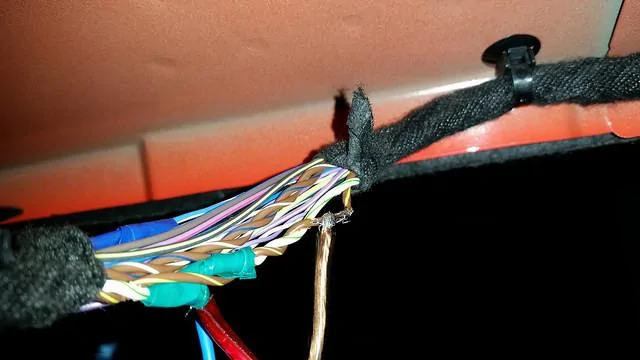
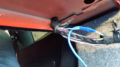
1. Expose the wires in the rear deck speaker wire harness. You can find this harness leading to the right rear speaker. It’s easiest to expose the wires before the harness splits off in a Y (closer to the rear seat). It’s easier if you pull out the plastic pop-connector thing that holds the harness to the sheet metal. Then, pull apart the black wire covering with your fingers. It will come apart:Brown-Yellow: Left speaker Negative
Brown-White: Right speaker Positive
Brown-Blue: Right speaker Negative
Blue-White (smaller gauge): 12V Switched (for telling your amp when to shut off)

EDIT: Boggus says "You can catch the same rear speaker wires from under the rear seat, easier since you won’t have to hang upside down."
2. One by one, carefully identify each of the four speaker wires that you need (see color code above) and pull it away from its paired wire as much as possible (the left & right wires for each speaker are twisted around each other).
3. Strip away part of the wire’s insulation (I think I took off about 1-inch - maybe less). I used automatic wire strippers. Whatever you use, be careful as the wires are a rather small wire gauge. Don’t cut the wire. Also, after you do the splice on one wire from each speaker wire pair, try to do the splice on the other wire from the pair farther down the line, that is not right next to the first wire’s splice (this will make it easier).
4. Splice new speaker wire onto each existing speaker wire. I soldered the new wires on (I’m sure there are other ways to go about it that don’t require soldering). I wrapped the stripped end of a new speaker wire around the exposed Ford speaker wire:
I then soldered them together (I don’t recommend tinning the new wire first, as that will make it near impossible to wrap it around the existing Ford wire):
5. Wrap the soldered connection with electrical tape:
6. If you plan on using the 12V switch wire to signal your amp to turn off and on, then repeat steps 2 through 5 for that wire. Be careful not to break the wire, as it’s thin and it is used to signal the rear camera IIRC.
7. Prepare to connect the wires to your amp’s wiring harness. I suggest thoroughly marking and documenting everything before proceeding. Write down the color codes of the Ford wires you spliced, and the colors of the added speaker wires (if they aren’t color coded then use tape or something to mark them), and the color codes of the amp harness wires. Make sure everything lines up on paper (left+ to left+, left- to left-, etc.). Double check all your connections before starting each one!
8. If necessary, cut your amp’s wiring harness. My Rockford Punch sub had RCA’s on the end of the harness, which needed to be cut off when using speaker level inputs. I cut the harness as close to the RCAs as possible, separated the wires a bit near the end, and stripped away some insulation. (If you’re using another amp/sub, you might not have a wiring harness to deal with - it might be as easy as connecting your new speaker wires right up to the amp.)
9. After you’ve triple-checked each wire pairing, connect the speaker signal wires to the amp harness wires. I soldered them and wrapped with electrical tape. I’m sure other methods would suffice.
10. Plug in your wiring harness (if applicable).
11. Turn on your car and test that the amp/sub works.
12. Tidy everything up: wrap up the black wiring cover around the original speaker wires, position/velcro your sub in place, cover your wires with wiring loom, yadda yadda.

13. If installing the RF Punch sub, attach the volume/gain remote and run it under the driver’s side trim panels just like you did with the power cable on the passenger side (this will be much easier, as the wire is smaller).
14. Adjust your gain, crossover frequency, etc. Enjoy.
Sponsored
Last edited:
