OGJET
Member
Hi Mike, yes but I can’t upload hpl files to this forum.I started to look at these but it's very hard in Excel. Do you have hpl logs?
Sponsored
Hi Mike, yes but I can’t upload hpl files to this forum.I started to look at these but it's very hard in Excel. Do you have hpl logs?
Looks like I'm wrong. I used to be able to convert but I forgot what I did.if you have SCT it will open the excel file and make it usable. It's called live link.

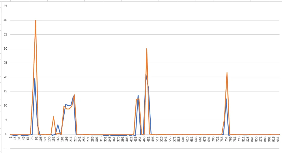
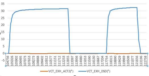
many thanks for your pictures, i tried something similar today and got thisi added all items from forscan regarding VCT, recorded a datalog, exported a csv, imported into excel, added graph of desired exhaust angle vs actual exhaust angle.


That is a great overview of how it all works.Whew, man that’s a lot.
The park position is 0 intake and 0 exhaust. The intake cams can advance 20 and retard 30 from there. The exhaust can only retard 50 and not advance. Negative is advance and positive is retard. There are 5 different cam schedules (disabled, emissions reduction, optimum stability, optimum fuel economy, optimum drivability, and optimum power). Various parameters determine what cam schedule is being used, but it’s mainly load and speed.
At idle they move to 20 intake, 0 exhaust which has very little overlap. At cruise they move to about 30, 50 (intake, exhaust), retarding both the maximum amount to extend the power stroke and reduce pumping losses. As load and speed increase the cams start moving towards the optimum power positions. At wot in optimum power, the intake starts fully advanced (-20) then retards to +10 as rpm rises. Exhaust stays in the 15 - 20 deg range.
There is a commanded and actual cam position for all 4 cams and it can be logged. You can also log error and phaser solenoid duty-cycle for all 4. Note that if any cam isn’t following commanded close enough then the pcm will use and report the more erroneous position of the two for BOTH, which makes no sense but that’s how it is. Also, if it gets bad enough it will disable vct. Total area under the error curve over time will eventually accumulate and it will throw a DTC, but this could take a while.
There are 4 phaser solenoids. These push on a shuttle valve in each cam. The shuttle valve directs oil to the advance or retard side of the phaser actuator. The Gen 2 phasers react very quickly as opposed to the slower ecoboost and Gen 3 exhaust phasers.
The pcm measures the cam position and compares to commanded. There is a feed-forward lookup then feedback PID portion of control to reduce the error down to less than the deadband. A resultant duty cycle is sent to the phaser solenoid.
In the pcm, ~13 different possible cam position combinations are defined and the engine is fully calibrated to run at any load and speed and any combination of cam timings. Each combination is called a mapped point. To further complicate things, each cam position combination is also fully calibrated to run with the imrc open or closed. So basically, something like 26 full engine calibrations exist in your pcm. The torque, speed density, borderline spark timing, and mbt are fully defined for each of the 26 mapped points. I’m sure you’re wondering by now why this is important to understand.….
The way it works is the pcm commands a position through a mapped point command, or between two mapped points. It doesn’t assume the cams are exactly where it commanded them to go. So at all times it is independently measuring the cam (and imrc) positions and using actual positions to determine which mapped point engine calibration data to use (how it interpolates is a whole other rabbit hole). Therefore, the (torque, sd, and timing) calibration data is for whatever the actual cam positions are, not what they are supposed to be. What this means is that the engine should “drive” almost completely normal even if the cams aren’t following commanded at all. In fact, I’ve electronically locked the cams in many different positions and drove around. The only time you could sense a difference was at idle and wot.
if you post logs I’ll look at them. Log Vct schedule and see if it’s going “disabled” (I suspect it is). It can go disabled for a number of reasons. You should also log the cam angles and cam solenoid duty cycles.I have some hpl logs if you would be able to look at them?
Any help would be much appreciated!
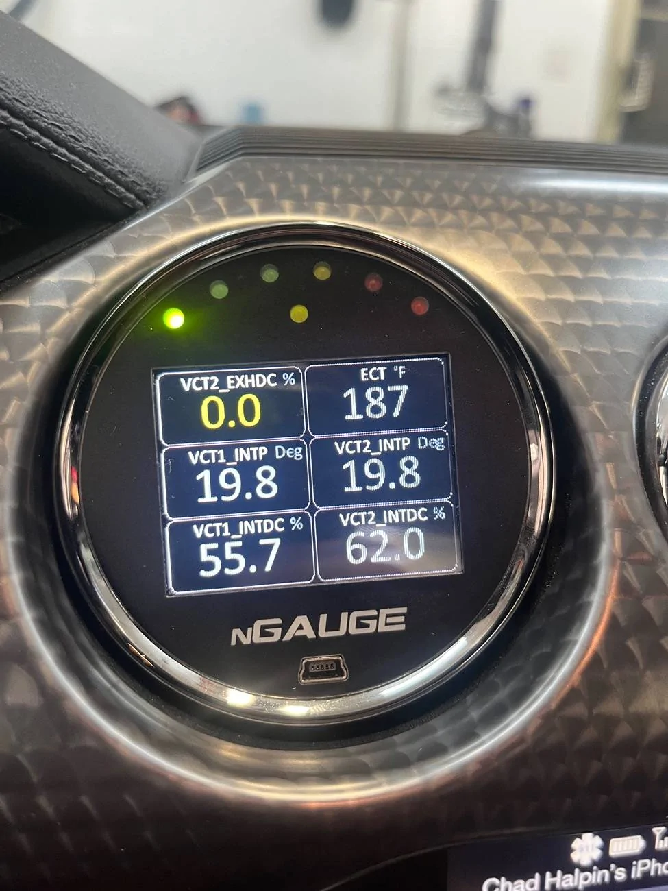
Thank you for the detailed write up. I’m monitoring VCT Intake Duty cycle on the pass and driversWhew, man that’s a lot.
The park position is 0 intake and 0 exhaust. The intake cams can advance 20 and retard 30 from there. The exhaust can only retard 50 and not advance. Negative is advance and positive is retard. There are 5 different cam schedules (disabled, emissions reduction, optimum stability, optimum fuel economy, optimum drivability, and optimum power). Various parameters determine what cam schedule is being used, but it’s mainly load and speed.
At idle they move to 20 intake, 0 exhaust which has very little overlap. At cruise they move to about 30, 50 (intake, exhaust), retarding both the maximum amount to extend the power stroke and reduce pumping losses. As load and speed increase the cams start moving towards the optimum power positions. At wot in optimum power, the intake starts fully advanced (-20) then retards to +10 as rpm rises. Exhaust stays in the 15 - 20 deg range.
There is a commanded and actual cam position for all 4 cams and it can be logged. You can also log error and phaser solenoid duty-cycle for all 4. Note that if any cam isn’t following commanded close enough then the pcm will use and report the more erroneous position of the two for BOTH, which makes no sense but that’s how it is. Also, if it gets bad enough it will disable vct. Total area under the error curve over time will eventually accumulate and it will throw a DTC, but this could take a while.
There are 4 phaser solenoids. These push on a shuttle valve in each cam. The shuttle valve directs oil to the advance or retard side of the phaser actuator. The Gen 2 phasers react very quickly as opposed to the slower ecoboost and Gen 3 exhaust phasers.
The pcm measures the cam position and compares to commanded. There is a feed-forward lookup then feedback PID portion of control to reduce the error down to less than the deadband. A resultant duty cycle is sent to the phaser solenoid.
In the pcm, ~13 different possible cam position combinations are defined and the engine is fully calibrated to run at any load and speed and any combination of cam timings. Each combination is called a mapped point. To further complicate things, each cam position combination is also fully calibrated to run with the imrc open or closed. So basically, something like 26 full engine calibrations exist in your pcm. The torque, speed density, borderline spark timing, and mbt are fully defined for each of the 26 mapped points. I’m sure you’re wondering by now why this is important to understand.….
The way it works is the pcm commands a position through a mapped point command, or between two mapped points. It doesn’t assume the cams are exactly where it commanded them to go. So at all times it is independently measuring the cam (and imrc) positions and using actual positions to determine which mapped point engine calibration data to use (how it interpolates is a whole other rabbit hole). Therefore, the (torque, sd, and timing) calibration data is for whatever the actual cam positions are, not what they are supposed to be. What this means is that the engine should “drive” almost completely normal even if the cams aren’t following commanded at all. In fact, I’ve electronically locked the cams in many different positions and drove around. The only time you could sense a difference was at idle and wot.
Thanks. A little background... I was getting Code P0340 and P0344. I replaced the Pass side intake cam phaser and the codes went away. The thing I can not understand is before I replaced the phaser, the Pass side intake cam always showed a duty cycle reading of 5%- 8% above the drivers side intake cam. After replacement, they seem to have switched and the drivers side is now consistently 5%-8% higher.I wouldn’t worry about that unless it sets a code or can’t control cam timing.
Are you getting any codes?I have the same issue as above. Mine can happen at WOT or part throttle. It falls flat on its face, VCT goes disabled, Lean condition and Fuel trims through the roof. My tuner is asking about grounding issues but I have double checked all. I'd be interested to see what eveyone finds out. Thanks! PSB
No codes and they recover right away, if I don’t let off it goes into a cycle of stumbles. Most of mine are between 4-5k.Are you getting any codes?
When you lean off the throttle, do the duty cycles resume? Or do they park at zero until you shut off the car and restart?
I don't know what the Duty Cycles % supposed to be at, but when I'm WOT they jump to either 0% or 80% but there's no difference in power. As soon as I lean off they go back to around 55%-65%. Everything feels normal.No codes and they recover right away, if I don’t let off it goes into a cycle of stumbles. Most of mine are between 4-5k.
