ShatterPoints
Well-Known Member
- Joined
- Apr 22, 2020
- Threads
- 3
- Messages
- 141
- Reaction score
- 115
- Location
- Austin Texas
- First Name
- James
- Vehicle(s)
- 2017 GT350
- Thread starter
- #1
A few people expressed interest in my suspension project based on some initial info I have posted previously. I will document my project here for those who may like to follow along, or use it as inspiration for their own tastes.
As a note I do not want to bash any aftermarket product, or anyone's decision to choose what they choose. If you are part of stance nation, cool, if you like stiff rides, cool, if you disagree with me cool. I am not here to tell you how you need to do things.
With that out of the way I called to get info about the s550 chassis and the gt350 specifically:
Steeda, BMR, and Cortex racing all gave me lots of their time and I would encourage people to start with these vendors for good info and a good experience. The only negative experience I had was talking with vorshlag, I will leave it at that.
The factory rear spring MR is 0.50:1
The factory rear shock MR is 0.70:1
With the cortex control arms the MR is increased to 0.77:1 - with coilovers the spring MR becomes the same.
I have spoken about flat ride in the past, when I first heard about it I thought it was BS. After lots of reading it turned out to be a valid configuration pioneered by GM. Lots of cars employ flatride today including the GT350 in its stock form that is why we run a stiffer spring in the rear, the very low rear spring MR of 0.50:1 allows us to run the 914lbs rear spring and not spin like a top. In short the idea is that as the car hits a bump there is a phase delay between the front and rear of the car. In order to address this delay the rear of the car must oscillate at a higher rate than the front. The tire, spring, shock, and linkage all contribute to the total ride rate for either end. This is expressed by undampened and dampened frequencies. So like a OEM, I chose to focus on a ride frequency to target front and rear. This number is ultimately meaningless. However it is the way to quantify the changes made to the car. (https://www.drtuned.com/tech-ramblings/2017/10/2/spring-rates-suspension-frequencies)
" For rough road operation spring rates are very important. It is necessary to take advantage of all of the suspension travel to keep the wheels on the ground as much as possible. If a flat ride (that is, the car lands flat after crossing a bump) is desired the spring rates must be adjusted to give slightly higher undamped natural frequency on the rear than on the front, i.e., approximately 10% stiffer on the rear. This often is not possible because of the high front spring rates required for front roll stiffness. " -Milliken RCVD
The OEM frequencies for the gt350 (non R) is ~1.35hz front and 1.55hz rear
Based on past experience I decided I'd like to increase overall stiffness expressed by the increased frequencies to a target of 2.0hz front and 2.2hz rear. This roughly maintains the factory split and I am hoping the overall balance to the car. I am also looking to maintain OE ride height as I do not have aerodynamic grip, I can afford to let the chassis move a bit more freely in order to gain mechanical grip.
I highly recommend this entire site be read a few times over. Lots of good info here:
http://farnorthracing.com/autocross_secrets6.html
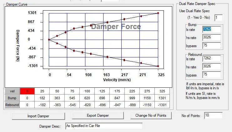
So with the springs chosen for the desired frequencies I need to obtain shocks that are able to dampen the bump/rebound with said springs. Using resources like milliken & milliken among the info posted above I plotted out a damper curve that I will result from custom valving performed on 2 way adjustable dampers.
These are my current plots, there is some small revision I will be making for a more flat blow off for a more digressive curve. I have not decided if I am happy with what I have right now.


I have calculated:
66lbs/in = critical damping for the front
72lbs/in = critical damping for the rear
I have settled on a low speed damping rate of 0.62 or 62% of critical for the front you can do the quick maths like so:
182/.025= 7280 (convert from si to imperial) 7280*.2214*.0254 = 41.49
41.49lbs/66lbs = .62
For the rear I have about 11% less damping so a low speed rate of 54% This is to accompany the higher spring rate and to control the weight transfer to the front under braking or other maneuvers. LESS damping = a faster damper = a tighter car (within reason of course)
I have chosen 3inches per second as my bypass or knee / transition point. The reasoning is a large majority of city driving and even tarmac racing for that matter the shock experiences 2-4 inches per second. A digressive damper is desirable so that you can have sufficient low speed damping but then an amount of blow off for pot holes, kerbs, or bumps. The blow off to less damping saves on the shock's lifespan while allowing for the chassis to not become out of shape over a moderate bump.
Like I said the jury is still out on the high speed section... I will update as I make up my mind where I want to start.
**I mistakenly posted the incomplete thread**
I'll roll with it and continue updating it
You will notice that I have a force matched damper curve. That means my bump and rebound are identical. It is perfectly fine to do this for a street car, and as I am learning takes some additional understanding to employ on a track car. The general rule is that cars with heavier sprung masses you want 2:1 or even 3:1 rebound to bump ratios. Rebound controls sprung mass, bump controls unsprung mass. This will result in a harsher ride when COMBINED with lowering your car from OE. This is because ANY bias in the R:B ratio will cause jacking. For rebound biased setups the end of the car will jack down onto the bump stops which act as an infinite spring rate. The opposite for bump biased setups, you will jack the end UP or cause it to launch over bumps. This of course happens over a series of bumps, OR a single large impulse.
With softer springs you can close the rebound to bump ratios as the bump setting is basically an inline spring with the rest of the system. Drivers also usually prefer the feeling of an over-dampened roll mode and so to combat that I will possibly be adding a larger front sway bar to balance that out. I have heard from a couple engineers that the 350 has terminal understeer and there is not a lot that can be done about that. It is an inherent "feature" of the chassis.
After having driven a car with force matched dampers I am inclined to believe that a slight rebound bias would be best for how I like the car to feel. I am not even sure what it would translate to around a track. I will find out in December when I get out to COTA. I will data log the OEM setup, repeat this a few times and then switch to my custom setup and data log some more.
--more to come.
As a note I do not want to bash any aftermarket product, or anyone's decision to choose what they choose. If you are part of stance nation, cool, if you like stiff rides, cool, if you disagree with me cool. I am not here to tell you how you need to do things.
With that out of the way I called to get info about the s550 chassis and the gt350 specifically:
Steeda, BMR, and Cortex racing all gave me lots of their time and I would encourage people to start with these vendors for good info and a good experience. The only negative experience I had was talking with vorshlag, I will leave it at that.
The above post was when I was looking at a spring change while maintaining the factory spring position. I was able to find a vendor (cortex racing) who sells aftermarket rear control arms which modify the mounting point for the shock, allowing us to fit conventional round end/ hole equipped shocks. They also sell magnaride delete kits.As far as springs which fit the stock location, only the steeda spring comes close with their 800/1280 dual rate. If I go coilover then swift 24k springs will be what I have to go with in the rear. I have asked the guys at vorshlag and they will sell a magnaride delete kit for the gt350. Its like $400 but ¯\_(ツ)_/¯
Motion ratios for struts are very close to 1:1 (typical is 0.98:1) Our cars have front struts. The spring is coiled over the strut and so its MR for the front is the same. This simplifies any sort of calculations needed to be performed. **To that end, I fully expect to have to pay to revise, or perform the revision myself with appropriate tooling as nailing something like this on the first try... well... doesn't happen.Back with an update for the route I am going. I found a vendor who sells magneride delete kits as well as they will custom valve a set of shocks for me.
I will be relocating the rear spring for a true coilover, this will mean the spring and shock motion ratio will be the same. The front does not change since they are struts to begin with. The rear shock MR is 0.77, so I will be using 450lbs springs front and 750lbs springs rear. I can make a separate thread discussing the valving I will be targeting for damping if anyone is interested.
The factory rear spring MR is 0.50:1
The factory rear shock MR is 0.70:1
With the cortex control arms the MR is increased to 0.77:1 - with coilovers the spring MR becomes the same.
I have spoken about flat ride in the past, when I first heard about it I thought it was BS. After lots of reading it turned out to be a valid configuration pioneered by GM. Lots of cars employ flatride today including the GT350 in its stock form that is why we run a stiffer spring in the rear, the very low rear spring MR of 0.50:1 allows us to run the 914lbs rear spring and not spin like a top. In short the idea is that as the car hits a bump there is a phase delay between the front and rear of the car. In order to address this delay the rear of the car must oscillate at a higher rate than the front. The tire, spring, shock, and linkage all contribute to the total ride rate for either end. This is expressed by undampened and dampened frequencies. So like a OEM, I chose to focus on a ride frequency to target front and rear. This number is ultimately meaningless. However it is the way to quantify the changes made to the car. (https://www.drtuned.com/tech-ramblings/2017/10/2/spring-rates-suspension-frequencies)
" For rough road operation spring rates are very important. It is necessary to take advantage of all of the suspension travel to keep the wheels on the ground as much as possible. If a flat ride (that is, the car lands flat after crossing a bump) is desired the spring rates must be adjusted to give slightly higher undamped natural frequency on the rear than on the front, i.e., approximately 10% stiffer on the rear. This often is not possible because of the high front spring rates required for front roll stiffness. " -Milliken RCVD
The OEM frequencies for the gt350 (non R) is ~1.35hz front and 1.55hz rear
Based on past experience I decided I'd like to increase overall stiffness expressed by the increased frequencies to a target of 2.0hz front and 2.2hz rear. This roughly maintains the factory split and I am hoping the overall balance to the car. I am also looking to maintain OE ride height as I do not have aerodynamic grip, I can afford to let the chassis move a bit more freely in order to gain mechanical grip.
I highly recommend this entire site be read a few times over. Lots of good info here:
http://farnorthracing.com/autocross_secrets6.html
So with the springs chosen for the desired frequencies I need to obtain shocks that are able to dampen the bump/rebound with said springs. Using resources like milliken & milliken among the info posted above I plotted out a damper curve that I will result from custom valving performed on 2 way adjustable dampers.
These are my current plots, there is some small revision I will be making for a more flat blow off for a more digressive curve. I have not decided if I am happy with what I have right now.

I have calculated:
66lbs/in = critical damping for the front
72lbs/in = critical damping for the rear
I have settled on a low speed damping rate of 0.62 or 62% of critical for the front you can do the quick maths like so:
182/.025= 7280 (convert from si to imperial) 7280*.2214*.0254 = 41.49
41.49lbs/66lbs = .62
For the rear I have about 11% less damping so a low speed rate of 54% This is to accompany the higher spring rate and to control the weight transfer to the front under braking or other maneuvers. LESS damping = a faster damper = a tighter car (within reason of course)
I have chosen 3inches per second as my bypass or knee / transition point. The reasoning is a large majority of city driving and even tarmac racing for that matter the shock experiences 2-4 inches per second. A digressive damper is desirable so that you can have sufficient low speed damping but then an amount of blow off for pot holes, kerbs, or bumps. The blow off to less damping saves on the shock's lifespan while allowing for the chassis to not become out of shape over a moderate bump.
Like I said the jury is still out on the high speed section... I will update as I make up my mind where I want to start.
**I mistakenly posted the incomplete thread**
I'll roll with it and continue updating it
You will notice that I have a force matched damper curve. That means my bump and rebound are identical. It is perfectly fine to do this for a street car, and as I am learning takes some additional understanding to employ on a track car. The general rule is that cars with heavier sprung masses you want 2:1 or even 3:1 rebound to bump ratios. Rebound controls sprung mass, bump controls unsprung mass. This will result in a harsher ride when COMBINED with lowering your car from OE. This is because ANY bias in the R:B ratio will cause jacking. For rebound biased setups the end of the car will jack down onto the bump stops which act as an infinite spring rate. The opposite for bump biased setups, you will jack the end UP or cause it to launch over bumps. This of course happens over a series of bumps, OR a single large impulse.
With softer springs you can close the rebound to bump ratios as the bump setting is basically an inline spring with the rest of the system. Drivers also usually prefer the feeling of an over-dampened roll mode and so to combat that I will possibly be adding a larger front sway bar to balance that out. I have heard from a couple engineers that the 350 has terminal understeer and there is not a lot that can be done about that. It is an inherent "feature" of the chassis.
After having driven a car with force matched dampers I am inclined to believe that a slight rebound bias would be best for how I like the car to feel. I am not even sure what it would translate to around a track. I will find out in December when I get out to COTA. I will data log the OEM setup, repeat this a few times and then switch to my custom setup and data log some more.
--more to come.
Sponsored
Last edited: