- Joined
- Mar 15, 2017
- Threads
- 18
- Messages
- 609
- Reaction score
- 336
- Location
- St. Louis, MO
- First Name
- Sam
- Vehicle(s)
- 2016 GT Premium PP
- Thread starter
- #1
This is a work in progress. I will add more pictures in weeks after posting this guide.
This guide overviews how to install the Active Exhaust from the 2018 Mustang to your 2015-2017 Mustang GT. You CAN in theory install these on your V6 or EcoBoost but different and extra modification must be done and it may not be a cut and clamp install like it is for the GT. If someone decided to install on an EcoBoost or V6 I will happily update this guide with your instructions if you chose to provide them.
This is by FAR the least expensive active exhaust possible. Total cost for me was under $450 doing all the work myself.
This DOES NOT FUNCTION like the factory 2018 active exhaust. It is not actuated in the instrument cluster or with driving modes. You manually control these with a switch. If you have a 2018 mustang you may be able to add the factory control but it has not been tried. If you want to try this please PM me and we can work out how to do it.
Note: This mod requires cutting of the stock rear valance which looks really bad. You either need to install a new valance or the 2018 Mustang rear bumper for a factory like finish. I’m waiting to see if these fit correctly under the Roush valance. They will not fit with the GT350 valance unless you modify it.
Big shout out to @Bsmith181992 AKA Ben Smith if you have seen him on one of the many Mustang Facebook pages. He helped me a ton in this and pioneered this swap. I just perfected it Just a note – this is how I installed everything. Ben may have done it slightly differently. There are many minor things you could do differently.
To preface this, you need minor electrical skills. It requires some soldering. You can also send me the valves and I can outfit them for you. PM me if you want to take advantage of this service.
Required tools:
-Dremel and plastic cutting bit
-Soldering iron and solder (unless getting valves from me)
-Assorted sockets
-Sawzall if installing mufflers yourself
-Fish tape (optional but makes it much easier)
-Interior removal tools (optional)
Required supplies:
-22 gauge minimum 16 gauge maximum high temp silicone wire. You’ll need at least 25’ maybe more. You only need a short run of the high temp wire but one 25’ roll * may * be enough.
-High temp silicone sealant
-Heat tape wrap – I used Tesa brand
-DPDT polarity reversing switch ON-OFF-ON
-Micro (ATC) Add-A-Fuse and 2A or 3A fuse.
-Small self tapping screw (optional but easy way to ground)
-Assorted electrical connectors (unless you want to solder everything)
-DC-DC Converter (100% optional to slow down motor speed)
Step 1: Order the Mufflers (and other parts)
Go to your local dealer and order:
JR3Z-5230-FA
JR3Z-5230-FB
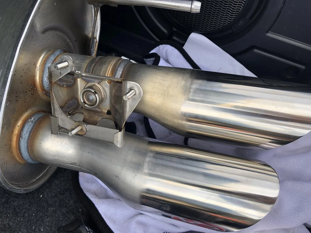
I was able to get them for $185 each plus tax. You can order them online but shipping will be very expensive. The mufflers include part of the piping to the resonator and the valves. It is an all in one piece.
It took about a week for mine to come in but your results may vary depending how many orders there are for them.

Step 2: Mod the Motors
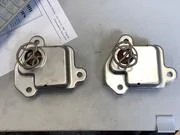
Once you get your new mufflers its time to mod the motors! Remove the motors by removing the 3 nuts on each motor. You can discard the wire hanging bracket or keep it if you want to zip tie your wires to it. I personally did not use it.
Remove the clip and heat shield on each motor. Remove the 3 metal inserts from the mounting holes on the motors.


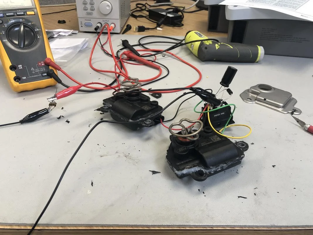
The scary part is cutting open the motors. You now need to carefully dremel the motors open. Be super cautious about cutting too deep. You must cut through the mounting holes and one side of the mount will break off. This is OK.
Once they are opened remove the circuit board by carefully prying up carefully. Try not to bed the pins too badly.
Solder one wire onto each one of the left pins going to the motor. I then soldered the other end of the wire to pins 1 and 4 on the motor. The polarity is not important. However, you need to make sure you wire both motors the same. If you don’t one motor will open while the other one closes.
Once that is finished make sure the gears line up correctly and close both sides of the case. I recommend clipping wires onto the two pins and testing the motor function with a battery while holding the case closed. Reverse the polarity and try again to make sure it goes both ways. If it works seal it up with silicone and let it sit overnight.
Next solder wires to the pins in the connector. Make sure they are long enough to make it into the trunk. The left muffler should be about 3-5’ right 2-3’. This step is kind of difficult. You’ll need a soldering iron with a smaller tip then most soldering guns. Once you solder the wire I recommend filling it up with silicone. It is important this wire is silicone due to the high temps from the exhaust. You really don’t want the insulation to melt through and short.
Install heat wrap tape all the way from the connector to about 3-4 feet up the wire. You want the wire to make it into the car with the tape on it. It will not only protect it from heat but also debris and cuts.
After the connector is dry re-install the motors on the mufflers. Note: If the valves won’t line up right move the motor position slightly with a battery.
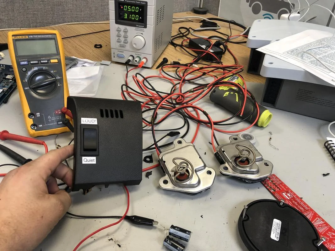
Step 3: Setup the Switch
I ordered this switch but you can use any DPDT ON-OFF-ON polarity reversing switch: https://amzn.to/2EVs8Nr
You’ll need to decide where you want to place the switch. Ben decided to use the little piece of trim with the interior temp sensor on it and I decided that was a good place too. Remove it by pulling straight out on it. You may need to move the steering wheel to get a better grip. Release the retaining strap and electrical connector for the air temp sensor.
I measured the switch area and marked it on the tirm piece. I then drilled a hole and used a routing tool on my dremel to make a hole large enough for the switch. Once your hole is the right size you just push it through.

You can either use the crimp connectors or solder wires directly to the switch. Up to you. You need a wire to go from the interior fuse box to the switch and the one to ground. It does not matter which set of pins connect to the power and which to motors but I recommend using the crossover pins for the motors.
I added a DC-DC converter here as well. The reason for this is at 12-15V the motors move SUPER fast. They open and close in less then a second.
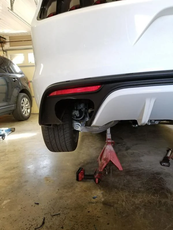
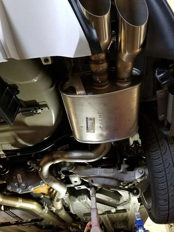
Step 4: Install the Mufflers
Skip this step if you want and just cut your valance and have an exhaust shop install them. Otherwise follow the steps below.
This is honestly pretty easy. You need either two 2.5” band clamps or two 2.5” couplers and 4 2.5” clamps. These are easy to get at any parts store. Seems that NAPA only carries the band clamps though.
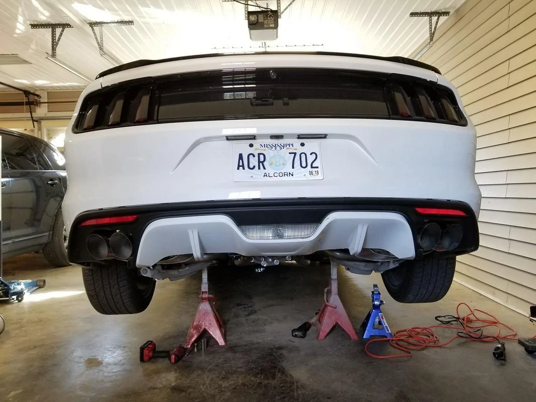
Put the car in the air and set the mufflers underneath the current ones. Look at the hanger position and be sure to line that up along with the pipes. You can then see about how you need to cut the rear valance. Use a plastic cutting wheel and carefully cut the valance to try and match the new tips. Look at the pics to see how Ben did it and I recommend learning from his mistakes and cutting them slightly differently. Mine look even worse then his so I’m not going to bother posting the pics.
Next, measure the length from the inside of the end of the pipe. These can be slightly different from the factory. Then measure the same length on your stock pipe and mark it. If using a band clamp cut it just slightly longer if using the coupler cut it a decent amount longer. Don’t cut it too short. It is a lot easier to make a second cut then add another piece of pipe. I had to make 2 cuts on one side. You will need to use a 13mm socket to remove the rear hangers. This makes it quite a bit easier to remove the exhaust. Drop the old mufflers out and put the hanger on the new muffler.
Push the muffler into the rear hanger and then either slide the pipes together if using a coupler or put your band clamp on. You may have to pull on the old exhaust to get it to line up for the coupler. Be sure to get the front hanger installed and tightened back down!

Step 5: Run the wires
On the passenger side there is a small round plug near the very rear of the car. Pop it out. Put a hole in it with a screwdriver or pen or something similar. Doesn’t need to be cut through. Stick your 4 wires from both motors through the hole and push all your extra wire up into the trunk and pop the plug back in. Be sure to zip tie the wires to whatever you can to make sure they don’t rub on anything.
Once in the trunk you can run the wire however you want. I recommend splicing the two wires together at this point. I just used T-Taps to connect the two. This way you only run two wires instead of 4 to the swtich. Since I have no spare tire I just ran it straight through the around to the left side of the trunk to make its way up the drivers side of the car.
Remove the back seat by pushing the clip in under the middle of each seat. The seat then pulls straight up. Lower the back seats and get the wire under the carpet. Be sure it won’t get pinched by the seats moving up and down.
Pull the middle trim off of the driver side foot rail area. Pull straight up. Also pull the lower left dash trim off. Pull straight out to remove. Run the wire through the trim that extends from the rear drivers side to the seat. Then run it all the way up under the dash how you’d like. Run the wire across the lower side of the kick panel and pull it out where the switch will go. Be sure to zip tie it under the kick panel so it doesn’t fall and get in the way of your feet.
Next, run a power wire from the passenger side fuse box. It is in the right side of the passenger footwell. Remove the cover by pulling out and up. I put my add-a-fuse near the top left of the box on a 7.5A fuse. This was a switched power fuse that only enables the motors when the ignition is on. If you want you can use a different circuit. Be sure to put a smaller 1A (if using DC-DC converter) or 2A fuse (if using full 12v power) in your circuit.
Note: The reason we use a small fuse is to keep the motors from burning out. If your switch gets stuck somehow the motors combined will bind and pull over 1A current. After a while of this binding the fuse will blow. If the motors are able to continuously draw power indefinitely they will burn out. The fuse of course is also for safety incase of short circuiting.
The ground proved to be a tad harder then I expected. You can look around and add it to another body ground or T-Tap into a ground wire that’s big enough (22GA or larger). I just used a self tapping screw and screwed right into the metal under the kick panel. Easy and effective. Used a crimp ring terminal to get back to the switch.
Step 6 (optional): Install a DC-DC converter.
I have a switcher design I engineered and build myself that’s multipurpose. It takes a 9-20v input and has a 0.8-6v output. I set it to 4.3V and added a flyback diode and 1mF 6.3V capacitor. If adding a DCDC converter the large capacitor is required for cold temp starting of the motors. A flyback diode is recommended due to the inductive load of the motor suddenly switching off. It allows the current to flow back into the motor and use that inductive energy instead of sending it back into the converter. I’m happy to sell these converters. PM if interested. I have never had one fail. I’ve had the cheap Chinese converters fail after mere months of use. These have been tried and tested for over a year in outdoor applications with constant current demand.
The converter will have the power and ground to the car and then the output of it will go to the middle pins on the switch. The motors still go directly to the polarity reversing outside pins of the switch. This substantially lowers the speed at which the motors operate and can give you finer control over them. It may also increase the life of the motors – though I don’t think their life will be a problem due to the limited use they get.
I put these motors with switch and my DC DC converter in a temperature chamber at -30ºF and the motors still started and functioned both ways. Temperature is not an issue.
Step 7: Button Everything Up and Test!
Once all of your wires are connected plug the temp sensor back in and push your trim piece back in. Make sure all of your wires are zip tied and out of the way.
Test the motors and make sure they work! If they don’t be 100% sure the switch is getting power. A standard multimeter will work. If you run into other issues feel free to PM me.
This guide overviews how to install the Active Exhaust from the 2018 Mustang to your 2015-2017 Mustang GT. You CAN in theory install these on your V6 or EcoBoost but different and extra modification must be done and it may not be a cut and clamp install like it is for the GT. If someone decided to install on an EcoBoost or V6 I will happily update this guide with your instructions if you chose to provide them.
This is by FAR the least expensive active exhaust possible. Total cost for me was under $450 doing all the work myself.
This DOES NOT FUNCTION like the factory 2018 active exhaust. It is not actuated in the instrument cluster or with driving modes. You manually control these with a switch. If you have a 2018 mustang you may be able to add the factory control but it has not been tried. If you want to try this please PM me and we can work out how to do it.
Note: This mod requires cutting of the stock rear valance which looks really bad. You either need to install a new valance or the 2018 Mustang rear bumper for a factory like finish. I’m waiting to see if these fit correctly under the Roush valance. They will not fit with the GT350 valance unless you modify it.
Big shout out to @Bsmith181992 AKA Ben Smith if you have seen him on one of the many Mustang Facebook pages. He helped me a ton in this and pioneered this swap. I just perfected it
Just a note – this is how I installed everything. Ben may have done it slightly differently. There are many minor things you could do differently.To preface this, you need minor electrical skills. It requires some soldering. You can also send me the valves and I can outfit them for you. PM me if you want to take advantage of this service.
Required tools:
-Dremel and plastic cutting bit
-Soldering iron and solder (unless getting valves from me)
-Assorted sockets
-Sawzall if installing mufflers yourself
-Fish tape (optional but makes it much easier)
-Interior removal tools (optional)
Required supplies:
-22 gauge minimum 16 gauge maximum high temp silicone wire. You’ll need at least 25’ maybe more. You only need a short run of the high temp wire but one 25’ roll * may * be enough.
-High temp silicone sealant
-Heat tape wrap – I used Tesa brand
-DPDT polarity reversing switch ON-OFF-ON
-Micro (ATC) Add-A-Fuse and 2A or 3A fuse.
-Small self tapping screw (optional but easy way to ground)
-Assorted electrical connectors (unless you want to solder everything)
-DC-DC Converter (100% optional to slow down motor speed)
Step 1: Order the Mufflers (and other parts)
Go to your local dealer and order:
JR3Z-5230-FA
JR3Z-5230-FB
I was able to get them for $185 each plus tax. You can order them online but shipping will be very expensive. The mufflers include part of the piping to the resonator and the valves. It is an all in one piece.
It took about a week for mine to come in but your results may vary depending how many orders there are for them.

Step 2: Mod the Motors
Once you get your new mufflers its time to mod the motors! Remove the motors by removing the 3 nuts on each motor. You can discard the wire hanging bracket or keep it if you want to zip tie your wires to it. I personally did not use it.
Remove the clip and heat shield on each motor. Remove the 3 metal inserts from the mounting holes on the motors.

The scary part is cutting open the motors. You now need to carefully dremel the motors open. Be super cautious about cutting too deep. You must cut through the mounting holes and one side of the mount will break off. This is OK.
Once they are opened remove the circuit board by carefully prying up carefully. Try not to bed the pins too badly.
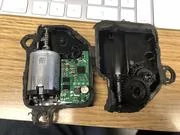
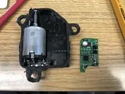
Solder one wire onto each one of the left pins going to the motor. I then soldered the other end of the wire to pins 1 and 4 on the motor. The polarity is not important. However, you need to make sure you wire both motors the same. If you don’t one motor will open while the other one closes.

Once that is finished make sure the gears line up correctly and close both sides of the case. I recommend clipping wires onto the two pins and testing the motor function with a battery while holding the case closed. Reverse the polarity and try again to make sure it goes both ways. If it works seal it up with silicone and let it sit overnight.
Next solder wires to the pins in the connector. Make sure they are long enough to make it into the trunk. The left muffler should be about 3-5’ right 2-3’. This step is kind of difficult. You’ll need a soldering iron with a smaller tip then most soldering guns. Once you solder the wire I recommend filling it up with silicone. It is important this wire is silicone due to the high temps from the exhaust. You really don’t want the insulation to melt through and short.
Install heat wrap tape all the way from the connector to about 3-4 feet up the wire. You want the wire to make it into the car with the tape on it. It will not only protect it from heat but also debris and cuts.
After the connector is dry re-install the motors on the mufflers. Note: If the valves won’t line up right move the motor position slightly with a battery.
Step 3: Setup the Switch
I ordered this switch but you can use any DPDT ON-OFF-ON polarity reversing switch: https://amzn.to/2EVs8Nr
You’ll need to decide where you want to place the switch. Ben decided to use the little piece of trim with the interior temp sensor on it and I decided that was a good place too. Remove it by pulling straight out on it. You may need to move the steering wheel to get a better grip. Release the retaining strap and electrical connector for the air temp sensor.
I measured the switch area and marked it on the tirm piece. I then drilled a hole and used a routing tool on my dremel to make a hole large enough for the switch. Once your hole is the right size you just push it through.

You can either use the crimp connectors or solder wires directly to the switch. Up to you. You need a wire to go from the interior fuse box to the switch and the one to ground. It does not matter which set of pins connect to the power and which to motors but I recommend using the crossover pins for the motors.
I added a DC-DC converter here as well. The reason for this is at 12-15V the motors move SUPER fast. They open and close in less then a second.

Step 4: Install the Mufflers
Skip this step if you want and just cut your valance and have an exhaust shop install them. Otherwise follow the steps below.
This is honestly pretty easy. You need either two 2.5” band clamps or two 2.5” couplers and 4 2.5” clamps. These are easy to get at any parts store. Seems that NAPA only carries the band clamps though.
Put the car in the air and set the mufflers underneath the current ones. Look at the hanger position and be sure to line that up along with the pipes. You can then see about how you need to cut the rear valance. Use a plastic cutting wheel and carefully cut the valance to try and match the new tips. Look at the pics to see how Ben did it and I recommend learning from his mistakes and cutting them slightly differently. Mine look even worse then his so I’m not going to bother posting the pics.
Next, measure the length from the inside of the end of the pipe. These can be slightly different from the factory. Then measure the same length on your stock pipe and mark it. If using a band clamp cut it just slightly longer if using the coupler cut it a decent amount longer. Don’t cut it too short. It is a lot easier to make a second cut then add another piece of pipe. I had to make 2 cuts on one side. You will need to use a 13mm socket to remove the rear hangers. This makes it quite a bit easier to remove the exhaust. Drop the old mufflers out and put the hanger on the new muffler.
Push the muffler into the rear hanger and then either slide the pipes together if using a coupler or put your band clamp on. You may have to pull on the old exhaust to get it to line up for the coupler. Be sure to get the front hanger installed and tightened back down!

Step 5: Run the wires
On the passenger side there is a small round plug near the very rear of the car. Pop it out. Put a hole in it with a screwdriver or pen or something similar. Doesn’t need to be cut through. Stick your 4 wires from both motors through the hole and push all your extra wire up into the trunk and pop the plug back in. Be sure to zip tie the wires to whatever you can to make sure they don’t rub on anything.
Once in the trunk you can run the wire however you want. I recommend splicing the two wires together at this point. I just used T-Taps to connect the two. This way you only run two wires instead of 4 to the swtich. Since I have no spare tire I just ran it straight through the around to the left side of the trunk to make its way up the drivers side of the car.
Remove the back seat by pushing the clip in under the middle of each seat. The seat then pulls straight up. Lower the back seats and get the wire under the carpet. Be sure it won’t get pinched by the seats moving up and down.
Pull the middle trim off of the driver side foot rail area. Pull straight up. Also pull the lower left dash trim off. Pull straight out to remove. Run the wire through the trim that extends from the rear drivers side to the seat. Then run it all the way up under the dash how you’d like. Run the wire across the lower side of the kick panel and pull it out where the switch will go. Be sure to zip tie it under the kick panel so it doesn’t fall and get in the way of your feet.
Next, run a power wire from the passenger side fuse box. It is in the right side of the passenger footwell. Remove the cover by pulling out and up. I put my add-a-fuse near the top left of the box on a 7.5A fuse. This was a switched power fuse that only enables the motors when the ignition is on. If you want you can use a different circuit. Be sure to put a smaller 1A (if using DC-DC converter) or 2A fuse (if using full 12v power) in your circuit.
Note: The reason we use a small fuse is to keep the motors from burning out. If your switch gets stuck somehow the motors combined will bind and pull over 1A current. After a while of this binding the fuse will blow. If the motors are able to continuously draw power indefinitely they will burn out. The fuse of course is also for safety incase of short circuiting.
The ground proved to be a tad harder then I expected. You can look around and add it to another body ground or T-Tap into a ground wire that’s big enough (22GA or larger). I just used a self tapping screw and screwed right into the metal under the kick panel. Easy and effective. Used a crimp ring terminal to get back to the switch.
Step 6 (optional): Install a DC-DC converter.
I have a switcher design I engineered and build myself that’s multipurpose. It takes a 9-20v input and has a 0.8-6v output. I set it to 4.3V and added a flyback diode and 1mF 6.3V capacitor. If adding a DCDC converter the large capacitor is required for cold temp starting of the motors. A flyback diode is recommended due to the inductive load of the motor suddenly switching off. It allows the current to flow back into the motor and use that inductive energy instead of sending it back into the converter. I’m happy to sell these converters. PM if interested. I have never had one fail. I’ve had the cheap Chinese converters fail after mere months of use. These have been tried and tested for over a year in outdoor applications with constant current demand.
The converter will have the power and ground to the car and then the output of it will go to the middle pins on the switch. The motors still go directly to the polarity reversing outside pins of the switch. This substantially lowers the speed at which the motors operate and can give you finer control over them. It may also increase the life of the motors – though I don’t think their life will be a problem due to the limited use they get.
I put these motors with switch and my DC DC converter in a temperature chamber at -30ºF and the motors still started and functioned both ways. Temperature is not an issue.
Step 7: Button Everything Up and Test!
Once all of your wires are connected plug the temp sensor back in and push your trim piece back in. Make sure all of your wires are zip tied and out of the way.
Test the motors and make sure they work! If they don’t be 100% sure the switch is getting power. A standard multimeter will work. If you run into other issues feel free to PM me.
Sponsored