GregO
Well-Known Member
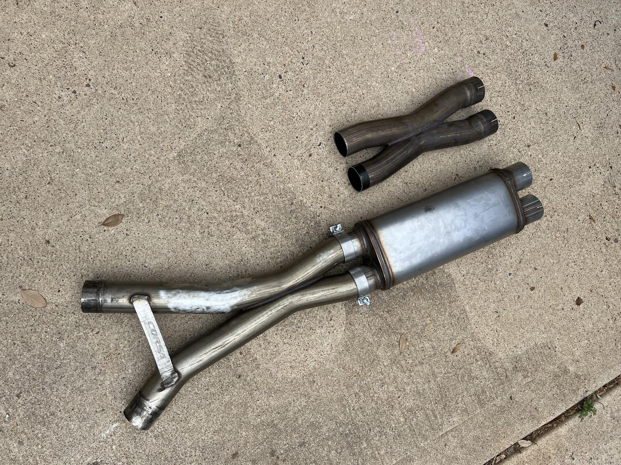
There’s a simple explanation on the flow difference.
The straight pipe isn’t expanded on the air draw through end whereas the muffler has both ends expanded for slip connections.
If the 18” straight tube had both ends expanded exactly like the muffler the air flow measurement would be nearly identical.
Just my observation.
Sponsored