OP
OP
mikes2017gt
Well-Known Member
- Joined
- Feb 21, 2017
- Threads
- 64
- Messages
- 999
- Reaction score
- 343
- Location
- San Antonio, TX
- Vehicle(s)
- 17 GT Prem M/T 3.55
- Thread starter
- #91
Was a busy family weekend, and I only had a few hours today to work on it, but I made progress.
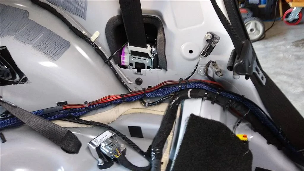
Power cable is run to the back. Zip-tied to factory loom. I just noticed that I missed a spot with the Tessa tape. Sloppy-ass work! ;)

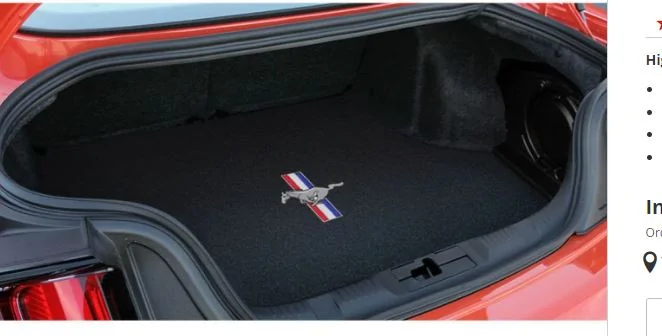
Based on how I'm running my wiring and trying to keep power cables away from signal cables, I decided to drop it down into the spare tire well here. My old 4-gauge was run this way too, but it was thinner, obviously. I'm not worried about the cable being damaged here. I threw cases of water in my trunk all the time and never had a problem w/the 4-ga in this location. The trunk floor sits on top of this, and it's padded underneath anyway. Cable will be A-OK.
I ran it around the well with zip tie bases. The white wire is the speaker wire going to the Stealthbox.
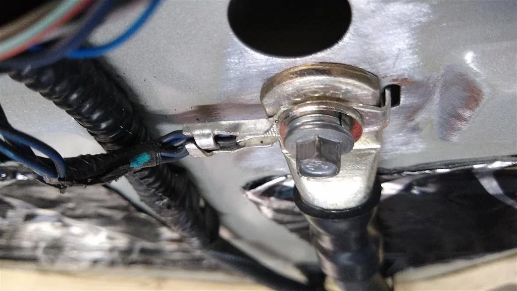
Got the ground cable installed. Was going to go with the spare tire hold down, but discovered that the height of the ring terminal + washers + bolt was too high and hitting the underside of the amp rack. I could dish out the bottom of the rack and will if this doesn't work. This is a factory ground point. Note the paint is ground off. There is a 1/4" steel washer and split-washer under the head of the factory bolt. It's on there solidly and the ring terminal is nice and flush on the panel. The sheet metal is a little thin for my liking, but it's a factory ground point and others have used it successfully, so I'll give it a shot.
Power and ground will come up through the amp rack right about where the two cables cross in this pic.
As I had to put the amp rack in the well anyway to make sure my power/ground cables were run out of it's way, I couldn't resist snapping a pic. First time the completed rack has ever actually been in the car! The covers are not on the amps in this pic. They're safely stored away for now.
I also got the tweeter wire run from the passenger side to the driver's side. This was a PITA. The carpet seems to have been installed before the dashboard was b/c the carpet runs under the dash/on top of the tranny tunnel and you can't get under it. I tried. But the wire is run, duct-taped down and out of harm's way. Also put the side panels back on the console, so that's completely back together.
If things go as planned, tomorrow I'll finally hear all this stuff make some noise. I have to solder the tweeter leads to the tweeter speaker harness, and then just run signal and speaker wires to the trunk. To say I'm anxious is an understatement. This build has been in the works for a lot longer than I'll admit.
I'm debating removing the factory amp, but probably will. I've got two big speaker harnesses and the RCAs that I'll have to ensure are well-secured and out of the way. Removing the amp should give me some more room and hopefully free up a few tie-down points for zip ties. Even with the driver's kick panel removed, it's still really difficult to see up there where the amp is.
I was looking at the pile of interior panels and started thinking "Do I remember what goes back in first?" Not sure I do but I'll figure it out. LOL!
Power cable is run to the back. Zip-tied to factory loom. I just noticed that I missed a spot with the Tessa tape. Sloppy-ass work! ;)

Based on how I'm running my wiring and trying to keep power cables away from signal cables, I decided to drop it down into the spare tire well here. My old 4-gauge was run this way too, but it was thinner, obviously. I'm not worried about the cable being damaged here. I threw cases of water in my trunk all the time and never had a problem w/the 4-ga in this location. The trunk floor sits on top of this, and it's padded underneath anyway. Cable will be A-OK.

I ran it around the well with zip tie bases. The white wire is the speaker wire going to the Stealthbox.

Got the ground cable installed. Was going to go with the spare tire hold down, but discovered that the height of the ring terminal + washers + bolt was too high and hitting the underside of the amp rack. I could dish out the bottom of the rack and will if this doesn't work. This is a factory ground point. Note the paint is ground off. There is a 1/4" steel washer and split-washer under the head of the factory bolt. It's on there solidly and the ring terminal is nice and flush on the panel. The sheet metal is a little thin for my liking, but it's a factory ground point and others have used it successfully, so I'll give it a shot.

Power and ground will come up through the amp rack right about where the two cables cross in this pic.

As I had to put the amp rack in the well anyway to make sure my power/ground cables were run out of it's way, I couldn't resist snapping a pic. First time the completed rack has ever actually been in the car! The covers are not on the amps in this pic. They're safely stored away for now.

I also got the tweeter wire run from the passenger side to the driver's side. This was a PITA. The carpet seems to have been installed before the dashboard was b/c the carpet runs under the dash/on top of the tranny tunnel and you can't get under it. I tried. But the wire is run, duct-taped down and out of harm's way. Also put the side panels back on the console, so that's completely back together.

If things go as planned, tomorrow I'll finally hear all this stuff make some noise. I have to solder the tweeter leads to the tweeter speaker harness, and then just run signal and speaker wires to the trunk. To say I'm anxious is an understatement. This build has been in the works for a lot longer than I'll admit.
I'm debating removing the factory amp, but probably will. I've got two big speaker harnesses and the RCAs that I'll have to ensure are well-secured and out of the way. Removing the amp should give me some more room and hopefully free up a few tie-down points for zip ties. Even with the driver's kick panel removed, it's still really difficult to see up there where the amp is.
I was looking at the pile of interior panels and started thinking "Do I remember what goes back in first?" Not sure I do but I'll figure it out. LOL!

Sponsored
Last edited: