
Sponsored

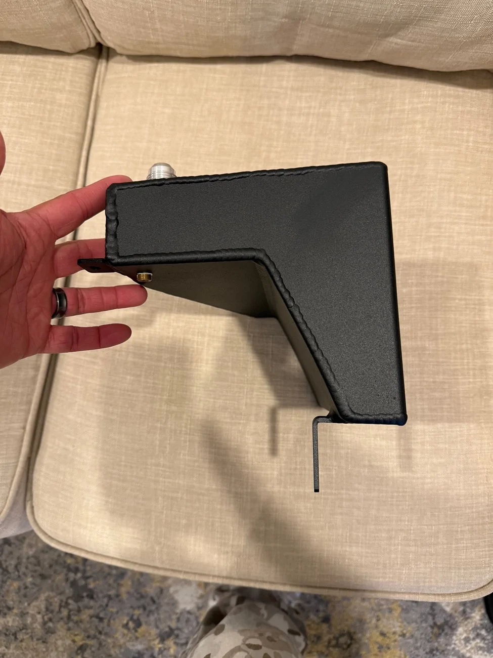
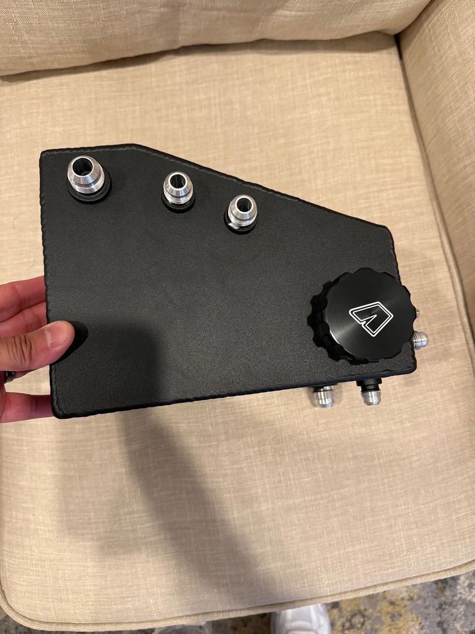
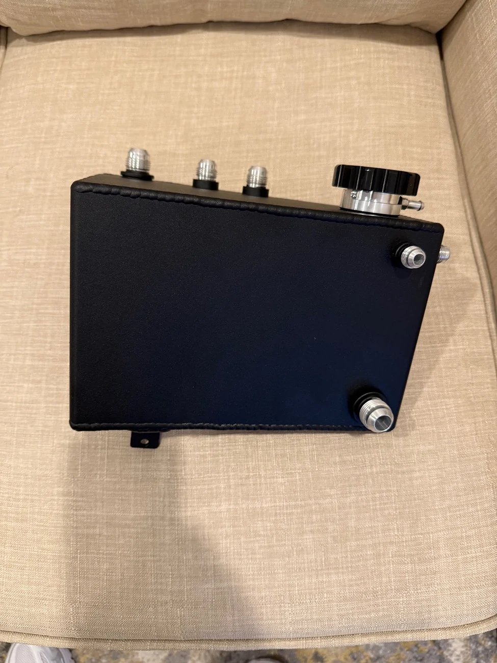
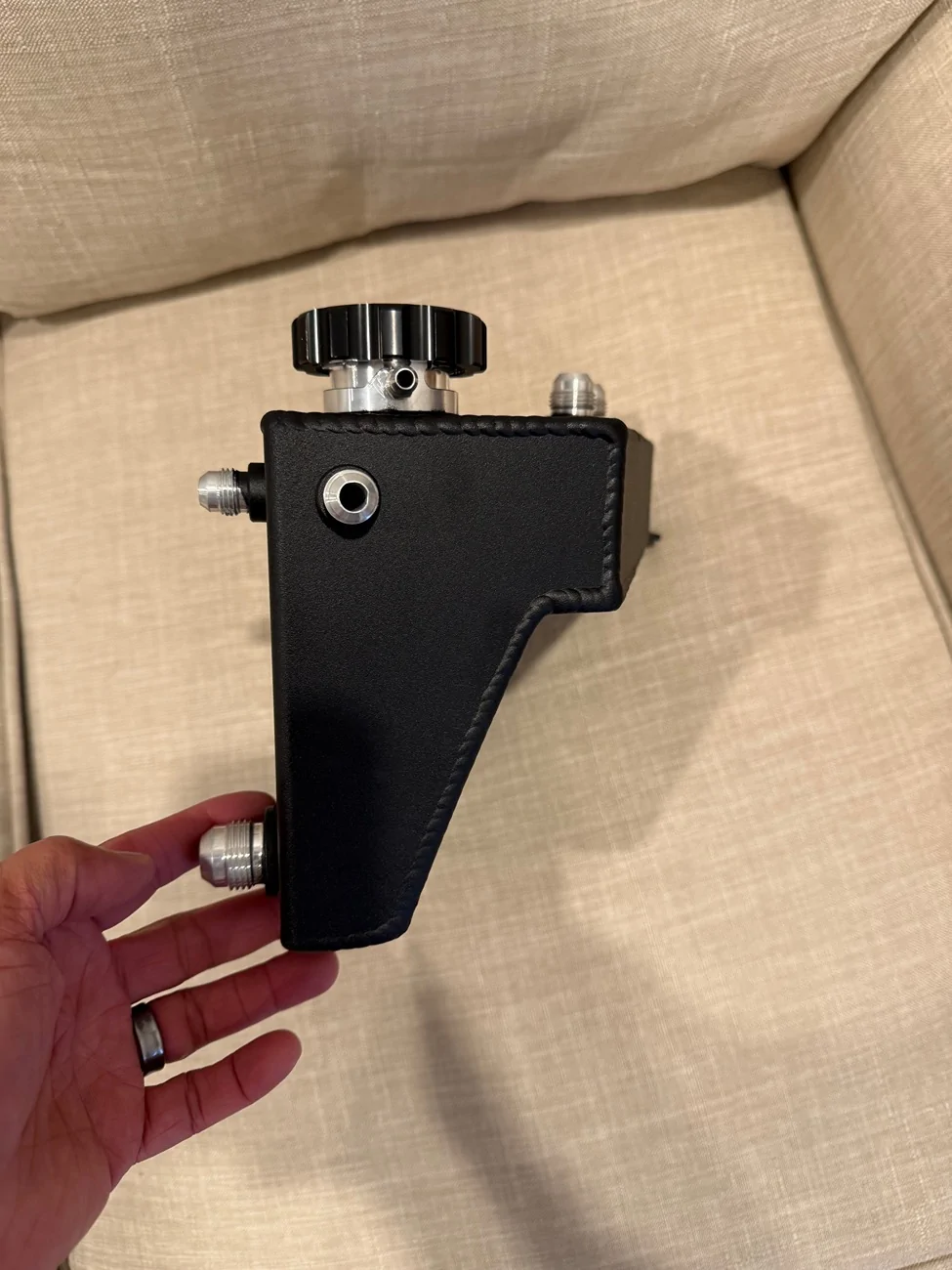
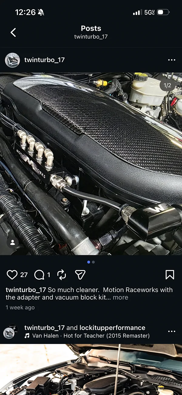
Motion Raceworks Coyote Mechanical Water Pump AN Fitting Kit

OP
OP
16RPG_Turbo

16RPG_Turbo

Well-Known Member
Joined
Jul 25, 2025
Threads
21
Messages
189
Reaction score
263
Location
Houston, TX.
First Name
Josh
Vehicle(s)
2016 Ford Mustang GT
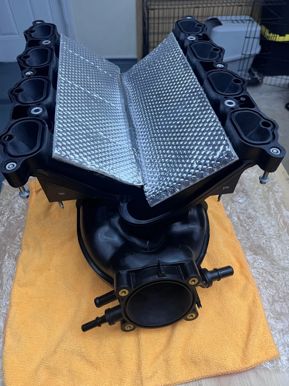
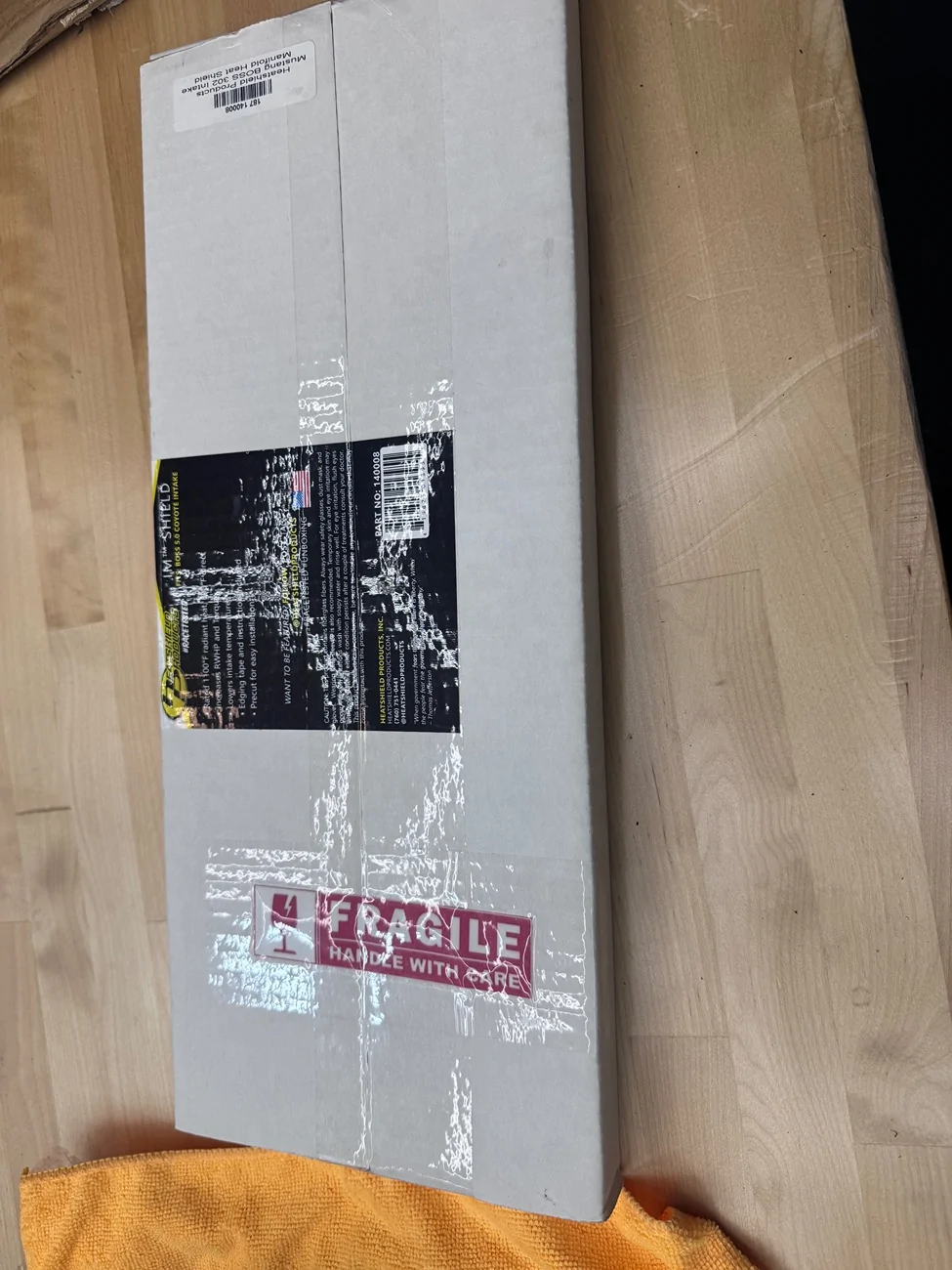
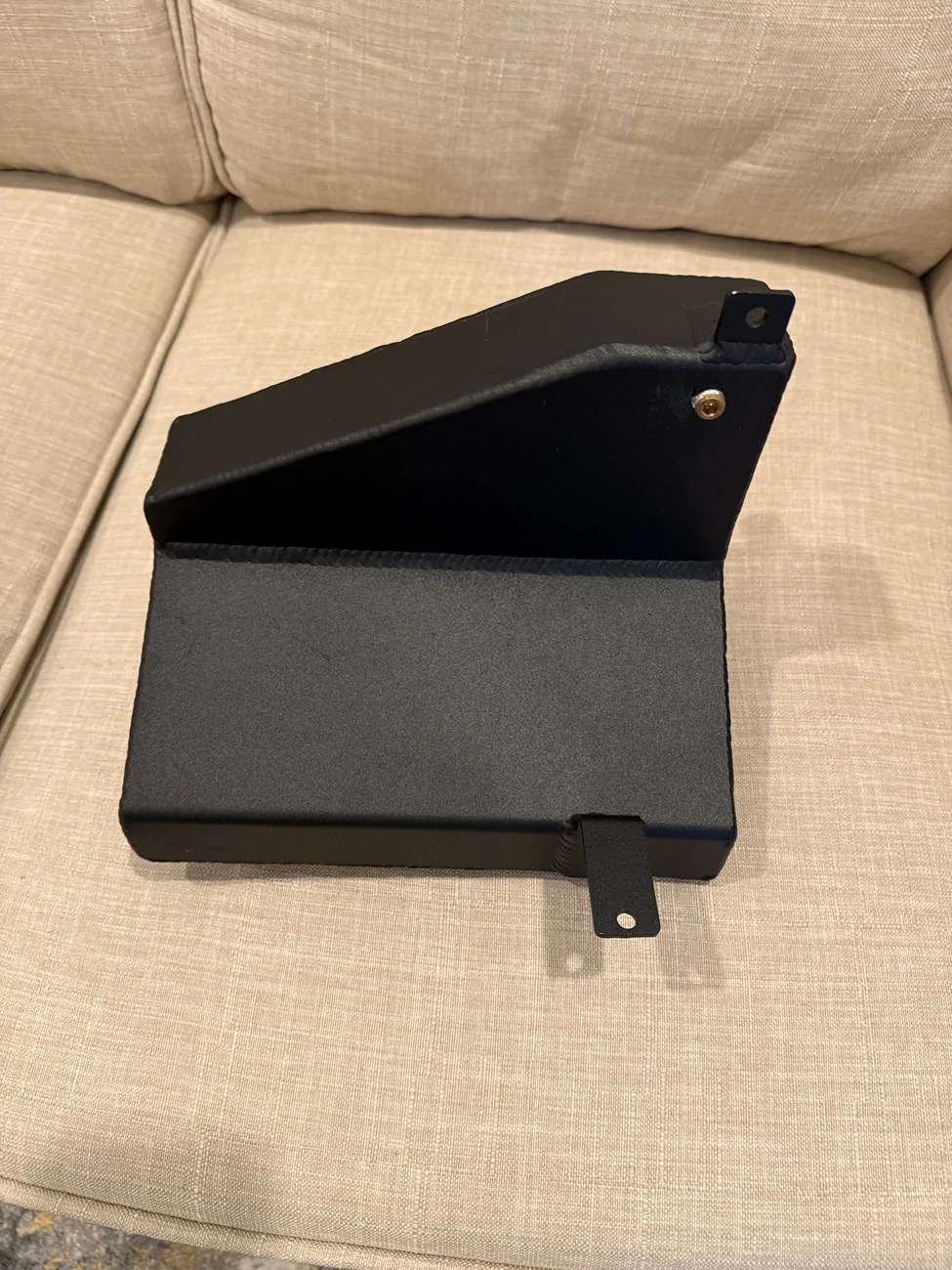
I just got done adding heat shield to the bottom of my Boss 302 manifold, but there is still a ton of room under there.

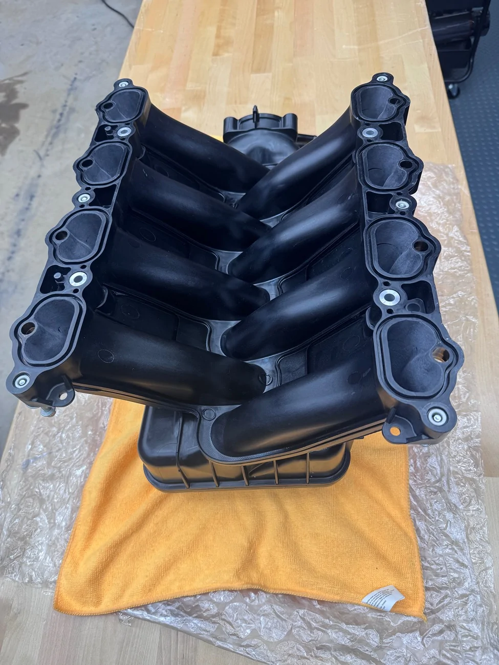
IMG_5960.webp


IMG_5962.webp


IMG_5961.webp
Sponsored


NGOT8R

Well-Known Member
Joined
Jul 19, 2020
Threads
154
Messages
9,272
Reaction score
7,780
Location
Florida
First Name
Adrian
Vehicle(s)
2019 Bullitt
In my case, I’m only cutting out the tstat because I’ll be running a Davies Craig electric water pump in pace of the factory mechanical pump. I will also be be deleting the factory coolant reservoir and running the BL Fab coolant reservoir/catch tank combo.

IMG_0065.webp


IMG_0062.webp


IMG_0061.webp


IMG_0063.webp


IMG_0064.webp
 

AcceptableNebula

Well-Known Member
Joined
Apr 5, 2023
Threads
19
Messages
339
Reaction score
958
Location
Massachusetts
First Name
Jake
Vehicle(s)
2023 Ford Mustang GT Premium
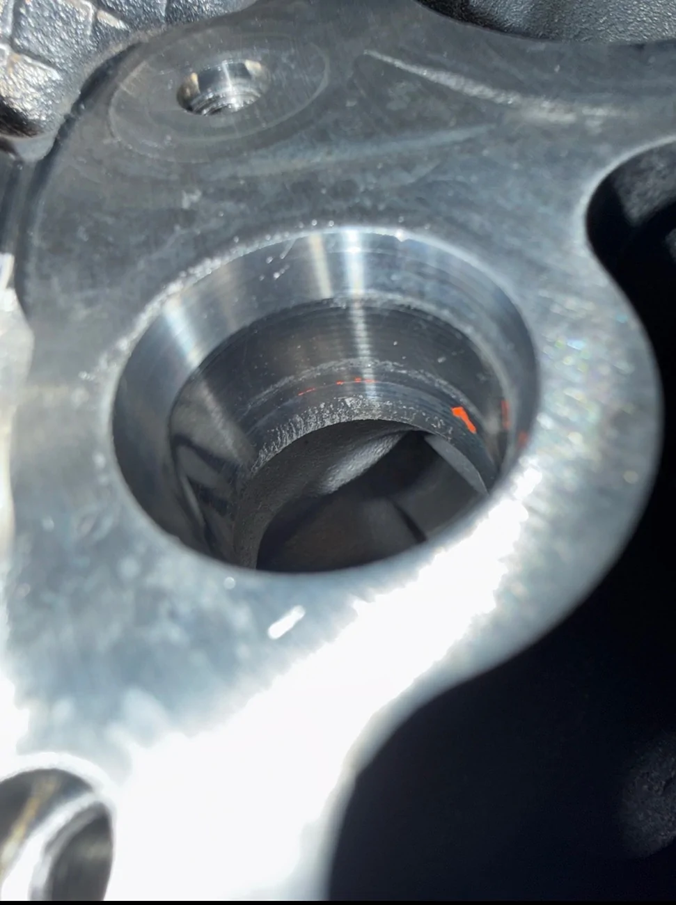
That bypass is too large in the picture in my opinion. You are discharging in what looks to be a 5/8” hose. While the factory heater hoses are 3/4”, that is just to accommodate the heater core connection. I don’t even run a bypass or heater core. That portion of the head flows coolant back to the drivers head via a crossover in the front of the block. There is no place to trap air and returning coolant directly back to the water pump is not beneficial. I’ve ran that passenger side heater core port capped since 2023 making over 900rwhp. You can see in the picture, once the machined portion of the bore ends, it is all cooling cavity area there. Thus why leaving it capped has never bothered me. Ford wanted 0.5-2 gpm going thru the heater core (estimated by flow restrictor orifice at assumed pump heads), so it clearly was for heating the cabin and not saving a cylinder head. Just my opinion. Do your own thing.

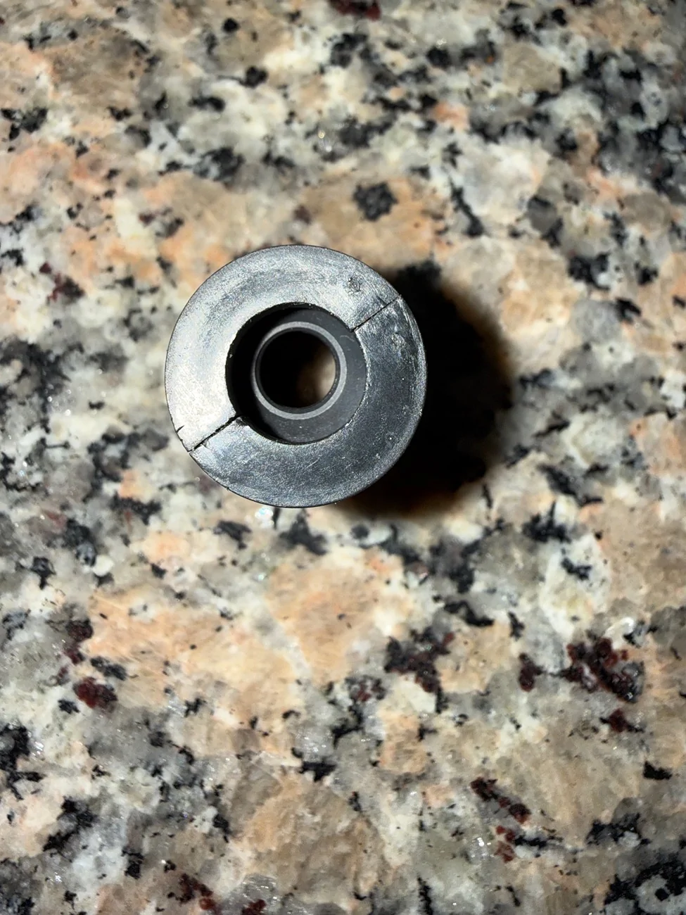
This portion is applicable to both stock water pumps and I’ll throw in the curveball for people with an EWP setup. On a stock water pump, the entrance to the water pump is the suction side of the pump. The discharge side of the pump occurs in the block cavity which doubles as the pump volute. Since this is the source of pump differential, the highest amount of it occurs here. Coolant and then discharged out of the pump to both sides of the block, prioritizing cylinder cooling and then up to the exhaust side of the heads, eventually working its way to the intake side then out the upper radiator hose. Turbulent flow through the block and heads generates frictional resistance to flow. Essentially chewing up some of the available pump differential. Without restriction, there would be no differential at all so it’s a good thing. Plus, turbulent flow is substantially better for heat transfer in this scenario. Now the factory heater core has 3/4” hoses supplying it, about 7’ worth, which will typically flow 4-6 gpm at acceptable velocities. A mechanical pump at 8000 rpm is not acceptable velocity lol. It generates a lot of pump head and can make a lot of coolant flow. For this reason, Ford installed a 9/32” flow restrictor (pictured) in that hose. The reason being that too large of a bypass would force the hottest coolant the coyote can give you directly back into the suction side of the pump. Not only would that wear out the aluminum heater core from excessive fluid velocity, you’d be dumping a large quantity of hot coolant back in with your freshly cooled coolant from the radiator only to be sent back to the engine. Also, the factory heater core offers its own level of resistance further slowing flow. Without restricted flow, the pump differential would drop as flow takes the path of least resistance. Since frictional resistance occurs over a distance, a short piece of 5/8” hose does not offer much. Picture blowing thru a 36” straw and then blowing thru the same straw at 1”. A 5/8” hose as these pump differentials will likely flow 5-7 gpm at its highest flow when the motor is at 7400 rpm. The time you need the cooling the most.

The bypass changes completely if running an EWP. Since the EWP-150 utilizes a replacement adapter in place of the stock water pump, the external pump mounted on a radiator hose now becomes the pump differential point. The bypass hose would have to return to a section of hose just before before the suction side of the EWP-150 as the stock pump cavity is now on the discharge side of the pump.

If you are running a Davies Craig water pump, which I’ve put in a car before, I would be shocked if it actually could flow enough for a high performance build. I bought the CWA400 from Pierberg and I’m likely going to run 2 (one before and one after the radiator) as I’m not sold the head and flow numbers are sufficient. Since I haven’t done the math yet, I’ll shelf this portion of it for now.

IMG_3984.webp


IMG_3983.webp
 
Last edited:

Sponsored

19BULLITTwhipple

Well-Known Member
Joined
Mar 23, 2021
Threads
29
Messages
291
Reaction score
171
Location
California
First Name
Ramzi
Vehicle(s)
Bullitt 2019
@NGOT8R & @19BULLITTwhipple

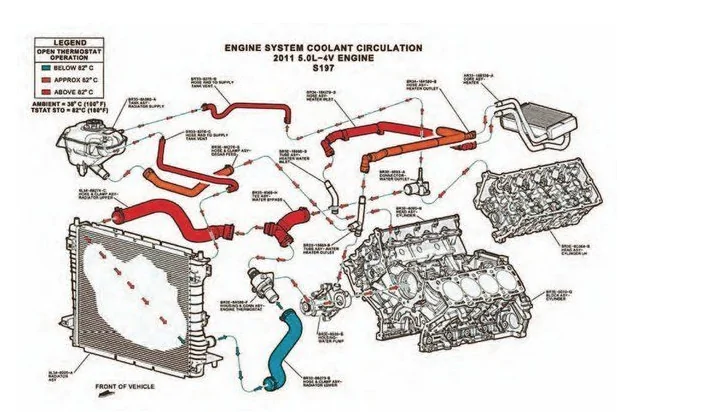
Based on the cooling schematic below, are y'all cutting out the heater core and the coolant reservoir?

1768930414267-0i.webp
I did cut out the Tstat, but I wouldn’t recommend it. My car takes a very long time to heat up and sometimes won’t even get up to operating temperature without me unplugged the fans. The water always circuiting is just too cold unless you do what @NGOT8R did and add an aftermarket water pump where you can manually set the temperature.

I had a problem with the coolant “Y” hose always leaking so I just made everything AN
 

NGOT8R

Well-Known Member
Joined
Jul 19, 2020
Threads
154
Messages
9,272
Reaction score
7,780
Location
Florida
First Name
Adrian
Vehicle(s)
2019 Bullitt
That bypass is too large in the picture in my opinion. You are discharging in what looks to be a 5/8” hose. While the factory heater hoses are 3/4”, that is just to accommodate the heater core connection. I don’t even run a bypass or heater core. That portion of the head flows coolant back to the drivers head via a crossover in the front of the block. There is no place to trap air and returning coolant directly back to the water pump is not beneficial. I’ve ran that passenger side heater core port capped since 2023 making over 900rwhp. You can see in the picture, once the machined portion of the bore ends, it is all cooling cavity area there. Thus why leaving it capped has never bothered me. Ford wanted 0.5-2 gpm going thru the heater core (estimated by flow restrictor orifice at assumed pump heads), so it clearly was for heating the cabin and not saving a cylinder head. Just my opinion. Do your own thing.

This portion is applicable to both stock water pumps and I’ll throw in the curveball for people with an EWP setup. On a stock water pump, the entrance to the water pump is the suction side of the pump. The discharge side of the pump occurs in the block cavity which doubles as the pump volute. Since this is the source of pump differential, the highest amount of it occurs here. Coolant and then discharged out of the pump to both sides of the block, prioritizing cylinder cooling and then up to the exhaust side of the heads, eventually working its way to the intake side then out the upper radiator hose. Turbulent flow through the block and heads generates frictional resistance to flow. Essentially chewing up some of the available pump differential. Without restriction, there would be no differential at all so it’s a good thing. Plus, turbulent flow is substantially better for heat transfer in this scenario. Now the factory heater core has 3/4” hoses supplying it, about 7’ worth, which will typically flow 4-6 gpm at acceptable velocities. A mechanical pump at 8000 rpm is not acceptable velocity lol. It generates a lot of pump head and can make a lot of coolant flow. For this reason, Ford installed a 9/32” flow restrictor (pictured) in that hose. The reason being that too large of a bypass would force the hottest coolant the coyote can give you directly back into the suction side of the pump. Not only would that wear out the aluminum heater core from excessive fluid velocity, you’d be dumping a large quantity of hot coolant back in with your freshly cooled coolant from the radiator only to be sent back to the engine. Also, the factory heater core offers its own level of resistance further slowing flow. Without restricted flow, the pump differential would drop as flow takes the path of least resistance. Since frictional resistance occurs over a distance, a short piece of 5/8” hose does not offer much. Picture blowing thru a 36” straw and then blowing thru the same straw at 1”. A 5/8” hose as these pump differentials will likely flow 5-7 gpm at its highest flow when the motor is at 7400 rpm. The time you need the cooling the most.

The bypass changes completely if running an EWP. Since the EWP-150 utilizes a replacement adapter in place of the stock water pump, the external pump mounted on a radiator hose now becomes the pump differential point. The bypass hose would have to return to a section of hose just before before the suction side of the EWP-150 as the stock pump cavity is now on the discharge side of the pump.

If you are running a Davies Craig water pump, which I’ve put in a car before, I would be shocked if it actually could flow enough for a high performance build. I bought the CWA400 from Pierberg and I’m likely going to run 2 (one before and one after the radiator) as I’m not sold the head and flow numbers are sufficient. Since I haven’t done the math yet, I’ll shelf this portion of it for now.

Great info! I’m gonna have to sit down and process all of this.

IMG_3983.webp
That’s some really good info! I’ll have to reread and process it better. The DC pump seems to flow like a fire hydrant though. Have you seen this video?


Last edited:

diambo4life

Well-Known Member
Joined
Sep 28, 2023
Threads
0
Messages
94
Reaction score
95
Location
OKC
First Name
Mike
Vehicle(s)
2014 Mustang GT 1998 GSX
I have wanted to convert mine but not running a thermostat is a big deal breaker for my street car which btw, I drove to work today when it was 30deg out. I will keep looking for a workable solution. Motivation is to clean up the upper/lower rad hose plumbing. I may be making some changes to my setup but like to visualize and plan ahead.
 

Sponsored

AcceptableNebula

Well-Known Member
Joined
Apr 5, 2023
Threads
19
Messages
339
Reaction score
958
Location
Massachusetts
First Name
Jake
Vehicle(s)
2023 Ford Mustang GT Premium
That’s some really good info! I’ll have to reread and process it better. The DC pump seems to flow like a fire hydrant though. Have you seen this video?
There are 2 metrics for determining pump performance. Pump head and pump flow. If you picture a curve, they are the 2 extremes of a pump. At 0 flow, you achieve what is called "shutoff head". Thats the maximum push of the pump, determined my the impeller size, and the length of the throw of the impeller. Longer the throw, more head. Wider the impeller width, the more gallons per minute (GPM) it does. The more gpm the less head the pump can generate. This is usually illustrated in a pump curve.

To bring you up to speed quickly on pump dynamics, non-priming pumps are not really pumps at all. They are differential engines. They create a differential in a closed system. So if a "pump" makes 23 ft of head, it means it creates 10 psi of differential pressure, generally split evenly between suction and discharge. If you had a system at rest (static) at 10 psi, turning on the pump, the discharge of the pump would read the static pressure of 10 psi + 5 psi of head. The suction side of the pump would read the static pressure of 10 psi - 5 psi of suction. So the gauges would read 15 psi and 5 psi respectively. This isn't absolute but there is no reason to dive into the cavitation rabbit hole today.

In the video demonstration, there are 2 things that are not applicable to a car application. First being that this is referred to as an open system. Water is leaving a tank and being dumped into a bucket. Since this is an open system, the weight of the water is quantifiable as 1 psi for every 2.31 feet above the discharge. In this scenario, even without the pump, the water would be leaving the tank at 1 psi assuming the column of water was 2.31 ft high, which is plausible. This provides that 1 psi to the inlet of the pump. This makes a low head pump like the EWP-150 show great performance because the other factor is there is not much trying to stop the water from leaving the pump.. Since there is no issue with flow (short and large diameter) on this system, the suction side of the pump is being pressurized by the tank of water, increasing the performance of the pump. Just like the turbocharger going into your engine since that is just a fancy air pump. If you are wondering what would be different in a closed system, the water would have to return to the tank, so the water coming down would be negated by the water going back up. So you don't consider the weight of the water in a closed loop with elevation changes.

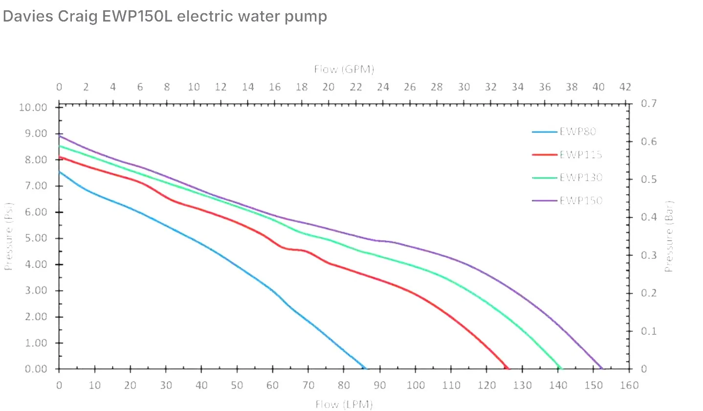
For comparison, the EWP-150 has a maximum amperage of 10a. That implies a 120 watt motor attached to it. The impeller is sized to achieve correct rpm of the 120 watt motor. With some digging I was able to find a pump curve for it. Since Watts is the true measurement of work being done, these numbers are not surprising.
  • At 0 L/min flow: 9 psi head (shut-off head)
  • At 50 L/min (~13.2 gal/min): ~6.5 psi head
  • At 100 L/min (~26.4 gal/min): ~5 psi head
  • At 150 L/min (~39.6 gal/min): ~0 psi head (full flow)
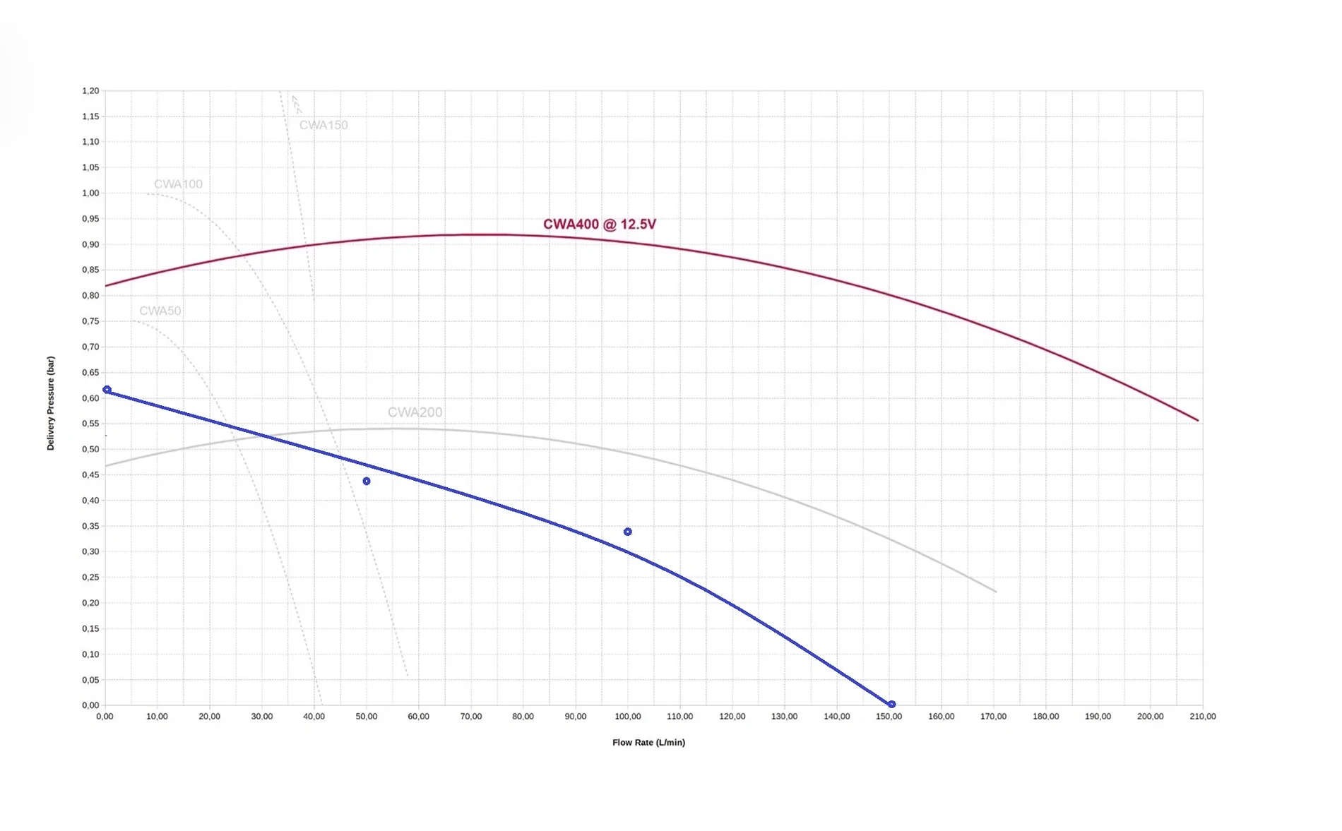
The Pierburg CWA400 however is a 36.3a @ 12vdc pump implying 430 watts. Almost 4x more powerful than the EWP150. That is reflective in its pump curve.
  • At 0 L/min flow: ~11.8 psi head (shut-off head)
  • At 50 L/min (~13.2 gal/min): ~13.3 psi head
  • At 100 L/min (~26.4 gal/min): ~13 psi head
  • At 150 L/min (~39.6 gal/min): ~11.6 psi head
  • At 210 L/min (~55.5 gal/min): ~8 psi head (full flow, not rated at 0 psi head)

Just for more useless information to fill your head with, I've attached the EWP150 and CWA400 pump curves but also overlaid the EWP150 on the same chart with a blue line. It also has other smaller models on it. On the left is the head and on the bottom is the flow rate. As you progress further right, that means more flow. The 400 is considered a flat curve pump, generally performs in similar head across its flow range. You can see the CWA50 and 100 models are steep curve pumps. They'll push hard at slow flow but quickly taper off when asked to flow more.

Davies Craig EWP150.webp


CWA400 pump curve.webp
 
Last edited:

NGOT8R

Well-Known Member
Joined
Jul 19, 2020
Threads
154
Messages
9,272
Reaction score
7,780
Location
Florida
First Name
Adrian
Vehicle(s)
2019 Bullitt
Wow! That‘s mind blowing. That’s a huge amp draw on the CWA400, but it does outrun the EWP150 by a good amount. I suppose running two of those would also be more beneficial than one as well. I looked at the CWA400 when I was looking for pumps, but real estate will be almost non existent with my hot snd cold side. I couldn’t imagine running two of those. Are they heavy co pared to the EWP150?
 

AcceptableNebula

Well-Known Member
Joined
Apr 5, 2023
Threads
19
Messages
339
Reaction score
958
Location
Massachusetts
First Name
Jake
Vehicle(s)
2023 Ford Mustang GT Premium
Considering 1400hp requires about 78 gpm for a ~30 degree delta T, assuming 30% engine efficiency, it’s worth any weight sub to 10 lb penalty. The main reason I want electric is I can run it while the big 1hp fan I use cools the car with it off. I still have more math to do before I commit. The Pierburg I have accepts PWM control. Now as of mid 2024, the Pierburg is basically on off until another control is figured out. It weighs just under 6 lbs.
 

AcceptableNebula

Well-Known Member
Joined
Apr 5, 2023
Threads
19
Messages
339
Reaction score
958
Location
Massachusetts
First Name
Jake
Vehicle(s)
2023 Ford Mustang GT Premium
Wow! That‘s mind blowing. That’s a huge amp draw on the CWA400, but it does outrun the EWP150 by a good amount. I suppose running two of those would also be more beneficial than one as well. I looked at the CWA400 when I was looking for pumps, but real estate will be almost non existent with my hot snd cold side. I couldn’t imagine running two of those. Are they heavy co pared to the EWP150?
There are 2 configurations you can run 2 pumps. Parallel or in series. If you put them in series you double the head output at the same flow rate of one pump. If they are parallel manifolded side by side you double the flow at the same feet of head of a single pump. So that’s why I have more testing to do before I commit. It’s plausible it’s just not viable for quadruple digit horsepower.
 
OP
OP
16RPG_Turbo

16RPG_Turbo

Well-Known Member
Joined
Jul 25, 2025
Threads
21
Messages
189
Reaction score
263
Location
Houston, TX.
First Name
Josh
Vehicle(s)
2016 Ford Mustang GT
Thank you for sharing that. That is a lot of useful information as I'm trying to make decisions on my build.


That bypass is too large in the picture in my opinion. You are discharging in what looks to be a 5/8” hose. While the factory heater hoses are 3/4”, that is just to accommodate the heater core connection. I don’t even run a bypass or heater core. That portion of the head flows coolant back to the drivers head via a crossover in the front of the block. There is no place to trap air and returning coolant directly back to the water pump is not beneficial. I’ve ran that passenger side heater core port capped since 2023 making over 900rwhp. You can see in the picture, once the machined portion of the bore ends, it is all cooling cavity area there. Thus why leaving it capped has never bothered me. Ford wanted 0.5-2 gpm going thru the heater core (estimated by flow restrictor orifice at assumed pump heads), so it clearly was for heating the cabin and not saving a cylinder head. Just my opinion. Do your own thing.

This portion is applicable to both stock water pumps and I’ll throw in the curveball for people with an EWP setup. On a stock water pump, the entrance to the water pump is the suction side of the pump. The discharge side of the pump occurs in the block cavity which doubles as the pump volute. Since this is the source of pump differential, the highest amount of it occurs here. Coolant and then discharged out of the pump to both sides of the block, prioritizing cylinder cooling and then up to the exhaust side of the heads, eventually working its way to the intake side then out the upper radiator hose. Turbulent flow through the block and heads generates frictional resistance to flow. Essentially chewing up some of the available pump differential. Without restriction, there would be no differential at all so it’s a good thing. Plus, turbulent flow is substantially better for heat transfer in this scenario. Now the factory heater core has 3/4” hoses supplying it, about 7’ worth, which will typically flow 4-6 gpm at acceptable velocities. A mechanical pump at 8000 rpm is not acceptable velocity lol. It generates a lot of pump head and can make a lot of coolant flow. For this reason, Ford installed a 9/32” flow restrictor (pictured) in that hose. The reason being that too large of a bypass would force the hottest coolant the coyote can give you directly back into the suction side of the pump. Not only would that wear out the aluminum heater core from excessive fluid velocity, you’d be dumping a large quantity of hot coolant back in with your freshly cooled coolant from the radiator only to be sent back to the engine. Also, the factory heater core offers its own level of resistance further slowing flow. Without restricted flow, the pump differential would drop as flow takes the path of least resistance. Since frictional resistance occurs over a distance, a short piece of 5/8” hose does not offer much. Picture blowing thru a 36” straw and then blowing thru the same straw at 1”. A 5/8” hose as these pump differentials will likely flow 5-7 gpm at its highest flow when the motor is at 7400 rpm. The time you need the cooling the most.

The bypass changes completely if running an EWP. Since the EWP-150 utilizes a replacement adapter in place of the stock water pump, the external pump mounted on a radiator hose now becomes the pump differential point. The bypass hose would have to return to a section of hose just before before the suction side of the EWP-150 as the stock pump cavity is now on the discharge side of the pump.

If you are running a Davies Craig water pump, which I’ve put in a car before, I would be shocked if it actually could flow enough for a high performance build. I bought the CWA400 from Pierberg and I’m likely going to run 2 (one before and one after the radiator) as I’m not sold the head and flow numbers are sufficient. Since I haven’t done the math yet, I’ll shelf this portion of it for now.

IMG_3984.webp


IMG_3983.webp
In my case, I’m only cutting out the tstat because I’ll be running a Davies Craig electric water pump in pace of the factory mechanical pump. I will also be be deleting the factory coolant reservoir and running the BL Fab coolant reservoir/catch tank combo.

IMG_0065.webp


IMG_0062.webp


IMG_0061.webp


IMG_0063.webp


IMG_0064.webp

[/Q
Sponsored


Top