engineermike
Well-Known Member
What’s the advantage of locking out the cams?
Sponsored
You get to have a coyote that chops and if someone asks you if it’s a ghost cam tune you get to tell them no I have real camsWhat’s the advantage of locking out the cams?

Less complexity in a race car setting. Unless real small cams it would make driving on the street unpleasant.What’s the advantage of locking out the cams?
I understand why they might be needed in a race car where valvespring pressures and rpm might cause loss of control, or perhaps one less failure point, and also very narrow rpm range…..but that’s not what we’re talking about here.Less complexity in a race car setting. Unless real small cams it would make driving on the street unpleasant.


")
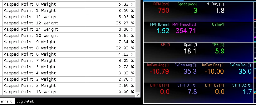
Set your spark plug gap at .040" and see if you still get misfire codes .Still having misfire code issues at high rpm even though I've set the misfire monitor to be disabled when in ghost cam mode.
Spark plugs are gapped way tighter than that. The misfire only happens on the ghost cam tune and it shows it detecting misfires at high rpm. I can’t figure out why as none of the things past 2k rpm are messed with.Set your spark plug gap at .040" and see if you still get misfire codes .
Anyways , any vids on it's 'ghost cam' idle ?
I know. That's why I said set em at .040" .Spark plugs are gapped way tighter than that.
Sure I still think I need a better understanding of the ford idle control to get it better dialed in and understand what parameters to change and what they all do.@tdstuart would you mind if we put this on our forums for future reference?
It is a common question and you've explained it very concisely.
https://forum.pcmtec.com
Someone sent me their tune and asked me not to share their exact tune. I haven’t been able to analyze the differences and why mine was throwing codes. It isn’t perfect and needs work, just haven’t had any time lately to dive into it. Are you using pcm tec?Were you able to work out those misfire kinks? How is drivability? I am looking at being tuned by Lund and they don’t offer novelty tunes anymore. I didn’t want to have it on all the time just as a party trick and it would be idiotic to dish out several hundred more bucks to have a reputable tuner do it for me.
FYI I posted a copy here for reference after speaking to tdstuart.@tdstuart would you mind if we put this on our forums for future reference?
It is a common question and you've explained it very concisely.
https://forum.pcmtec.com