OP
OP
2017GBGTPP
Well-Known Member
- Joined
- Jul 2, 2016
- Threads
- 14
- Messages
- 570
- Reaction score
- 748
- Location
- Albuquerque, NM
- First Name
- Dan
- Vehicle(s)
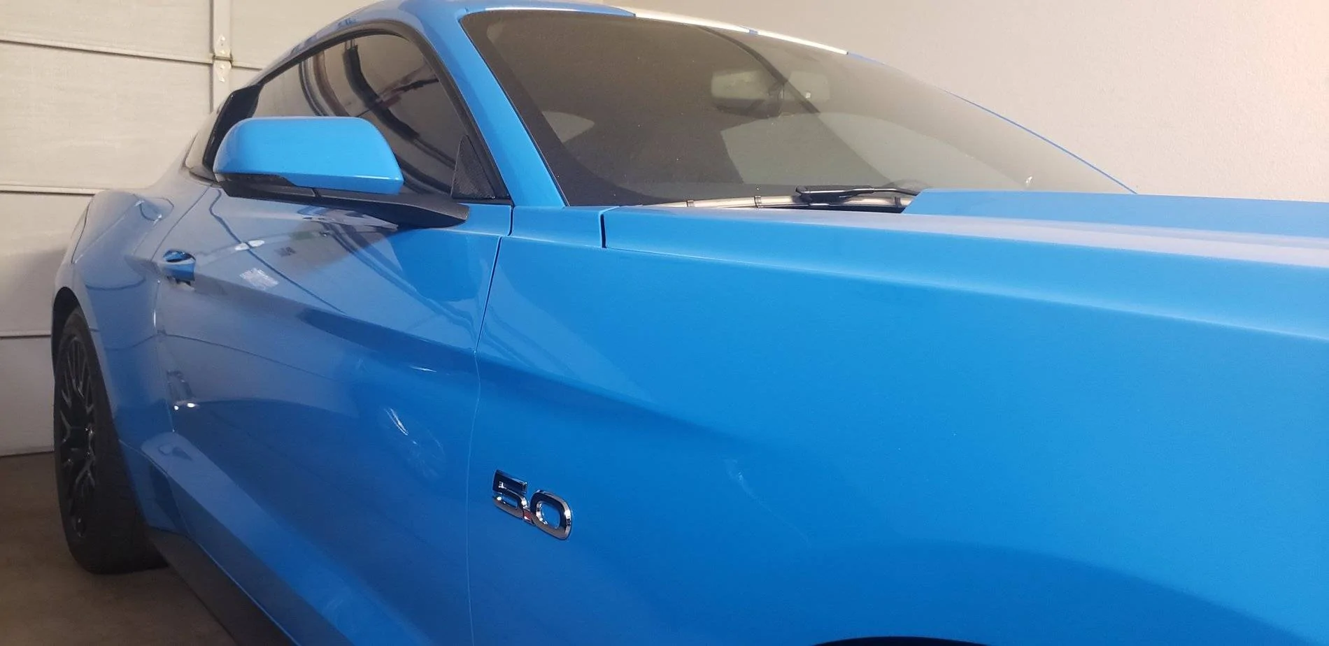
- 2017 Grabber Blue Premium GTPP w/ Recaros
- Thread starter
- #46
No problem, here you go! I'll try to get one at night too.I was wondering about the sequential lights from CJPP myself. Glad to see you did them and so far so good. Is it too much to ask if you can show a gif from the front? With the headlights on or off and the turn signals? Thanks!
Edit: Updated for a better gif with less glare. FYI the headlight DRLs aren't flickering, that's just a digital camera effect. Also, here's a front shot with the lights on:

Sponsored
Last edited:


") ). Based on your review and write-up I ordered the turn signals from CJ Pony Parts as well. As noted they arrive directly from Winjet and are a fairly straight forward install. I think they look better than some of the more expensive ones, and no hyperflashing... Thanks for the tip!
). Based on your review and write-up I ordered the turn signals from CJ Pony Parts as well. As noted they arrive directly from Winjet and are a fairly straight forward install. I think they look better than some of the more expensive ones, and no hyperflashing... Thanks for the tip!