axios
Active Member
- Joined
- Jul 20, 2018
- Threads
- 4
- Messages
- 43
- Reaction score
- 30
- Location
- Santa Cruz, CA
- Vehicle(s)
- 2015 Mustang GT PP
- Thread starter
- #1
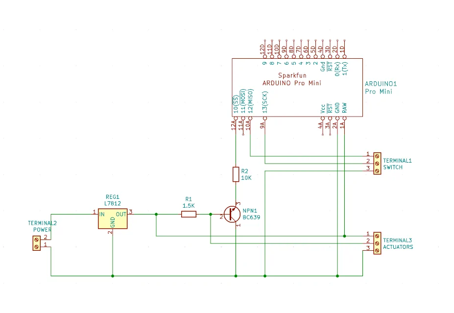
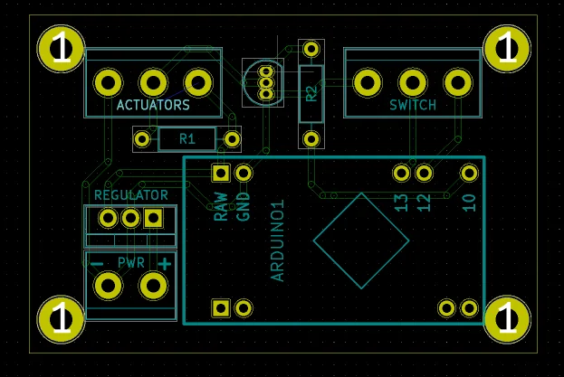
Hacking together an active exhaust setup using Arduino. I am actually using BMW exhaust valve actuators as they can be found for cheap on ebay + they're all made by one and the same company.
Got the actuators to spin both ways, next step is to solder everything up and add a fancy switch LOL

Got the actuators to spin both ways, next step is to solder everything up and add a fancy switch LOL

Sponsored

")