defector
Well-Known Member
- Joined
- Aug 27, 2016
- Threads
- 9
- Messages
- 47
- Reaction score
- 11
- Location
- Canton, Mi
- Vehicle(s)
- 2016 Mustang GT Premium PP
- Thread starter
- #1
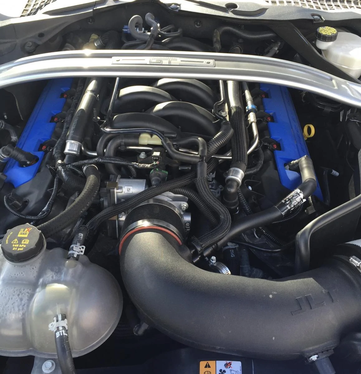
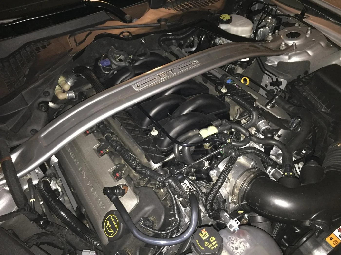
Finished install of the GT350 intake manifold yesterday. I created a new post as the current posts are way too long to read through and wanted feedback specifically on the items I mention.
1) Like most things, doing this twice would take 1/2 the time.
2) I can't believe Ford Performance is selling these without instructions.
3) You have to be nuts to not buy the JDM evap harness extension (there is no place to 'take out' wire from). I have mine installed taut right now but plan to buy the $29.99 extension immediately. I think another solution would be a mechanical adapter to rotate the valve slightly but I've ordered the harness.
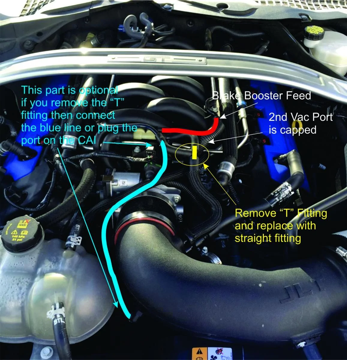
4) The information out there on the vacuum harness connections seems to be the most lacking.
5) Key things I'd share with others that I didn't see in other videos yet.
a) You must 'take out' wire for the purge solenoids from the rear engine harness. You will take this wire out from drivers side to passenger side and will need to take out about 3-4"s to avoid strain in these wires.
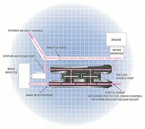
b) I believe some are misunderstanding how to connect the aspirator after I just saw this video. This video shows that the air induction system is connected to the VACUUM side of the intake. Not sure how this will run - maybe it gets by - but this is incorrect.
[ame="[MEDIA=youtube]z5a8wtkhZqY[/MEDIA]"][/ame]
c) How does the aspirator work? See the attached image from a Ford supplier's website. I think once you see this, you will understand how the routing must be connected, even if you must make your own.
d) From what a Ford engineer told me. The vacuum aspirator between the GT350 and GT are different. The GT350 makes more vacuum at low vaccum (WOT) and less vacuum at high vacuum (idle). I might switch back to the GT aspirator someday but for now kept the GT350 in there.
e) I have read some posts where people are saying, if you only show 17" of vacuum you have a vacuum leak. I don't believe this is true. After I installed the intake, I had 20" of vacuum strong before installing the Lund tune. After I flashed the Lund tune, it dropped to 17". Is that the whole story? I have no idea, but would like to see if others can share your findings here.
f) I see people putting the coolant hose plastic trays on top of the coolant hoses now, trapping them in place. That seems creative and OK, but I noted that my driver's side 'tray' is not straight and has a little kink to it, unlike some of yours.
Have not driven the car yet. Looking forward to that drive.
Jim


1) Like most things, doing this twice would take 1/2 the time.
2) I can't believe Ford Performance is selling these without instructions.
3) You have to be nuts to not buy the JDM evap harness extension (there is no place to 'take out' wire from). I have mine installed taut right now but plan to buy the $29.99 extension immediately. I think another solution would be a mechanical adapter to rotate the valve slightly but I've ordered the harness.
4) The information out there on the vacuum harness connections seems to be the most lacking.
5) Key things I'd share with others that I didn't see in other videos yet.
a) You must 'take out' wire for the purge solenoids from the rear engine harness. You will take this wire out from drivers side to passenger side and will need to take out about 3-4"s to avoid strain in these wires.
b) I believe some are misunderstanding how to connect the aspirator after I just saw this video. This video shows that the air induction system is connected to the VACUUM side of the intake. Not sure how this will run - maybe it gets by - but this is incorrect.
[ame="[MEDIA=youtube]z5a8wtkhZqY[/MEDIA]"][/ame]
c) How does the aspirator work? See the attached image from a Ford supplier's website. I think once you see this, you will understand how the routing must be connected, even if you must make your own.
d) From what a Ford engineer told me. The vacuum aspirator between the GT350 and GT are different. The GT350 makes more vacuum at low vaccum (WOT) and less vacuum at high vacuum (idle). I might switch back to the GT aspirator someday but for now kept the GT350 in there.
e) I have read some posts where people are saying, if you only show 17" of vacuum you have a vacuum leak. I don't believe this is true. After I installed the intake, I had 20" of vacuum strong before installing the Lund tune. After I flashed the Lund tune, it dropped to 17". Is that the whole story? I have no idea, but would like to see if others can share your findings here.
f) I see people putting the coolant hose plastic trays on top of the coolant hoses now, trapping them in place. That seems creative and OK, but I noted that my driver's side 'tray' is not straight and has a little kink to it, unlike some of yours.
Have not driven the car yet. Looking forward to that drive.
Jim
Sponsored