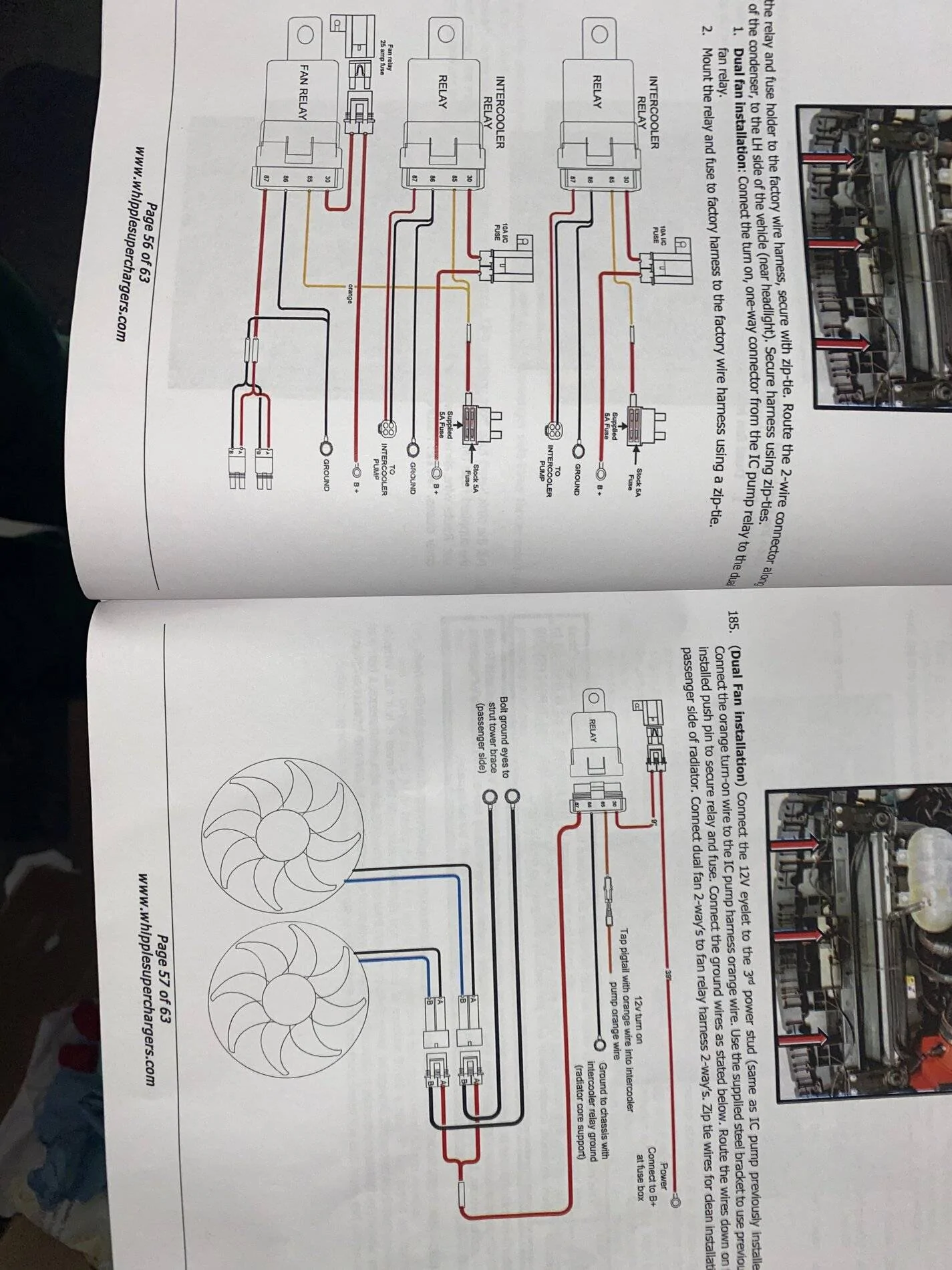
So I found this diagram searching, thinking they updated the design but no mention of it in the manual yet. I take it by this diagram the ic pump gets power from another source?
So I found this diagram searching, thinking they updated the design but no mention of it in the manual yet. I take it by this diagram the ic pump gets power from another source?
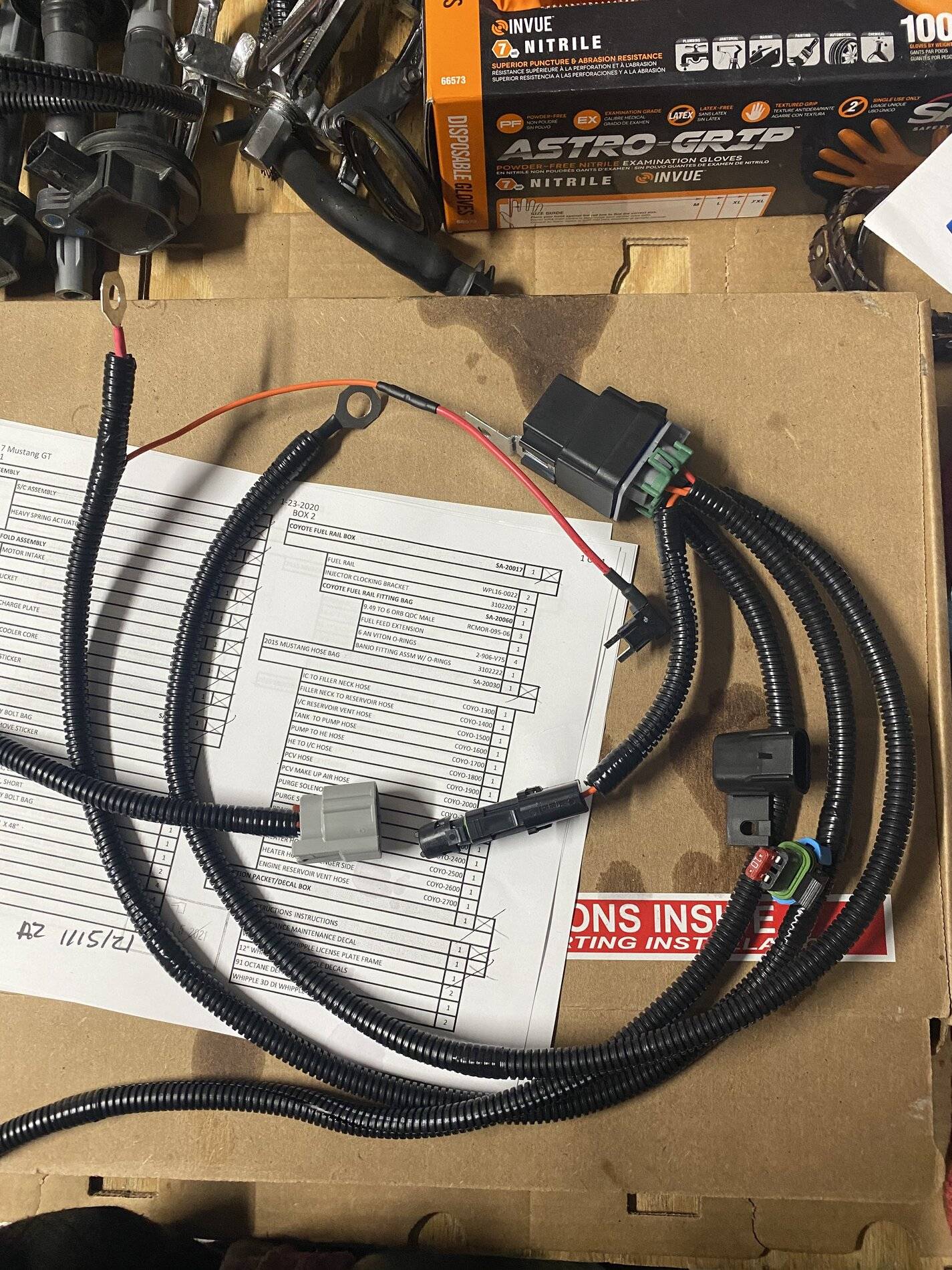
Looking at the wiring diagram, the red wire with a terminal ring goes to 12 positive dc. The green wire and black wires with terminal rings, go to ground. The only connector is the gray one and it goes to the pump. The cyli ndrical looking part to the right of the gray connector doesn't go anywhere. The end with the fuse has a cap. The wire harness looks ok to me.
What is the "blue plug" you are referring to? I think the instructions should have a step by step on where each connection goes, but like I stated earlier, it looks complete to me. I tried to locate the instruction manual on the Whipple website, but I couldn't find it to have a deeper look.
I found this diagram and it shows a plug in blue, but that is only for a kit that has the dual fans upgrade. Do you have the dual fans for the LTR, if not, the harness you have is the correct one. The blue plug uses a IMRC reference to control the dual fans.
After reading your second post. The red wire with the terminal ring connects to positive 12vdc and is the power to operate the coolant pump. The relay will trigger anytime you have the ignition on, so the fuse tap should be connected to a fuse that is only hot, with the ignition on.
If you aren't versed in reading wire diagrams, I'll give you a crash course. The relay is basically a switch. It's contacts are normally open and closes when it gets 12 volts dc to it. The red wire connected to the green wire of the fuse tap supplies the relay the power to close and has power when you have the ignition on. You have to install the fuse tap to a location that only has power when the ignition is on, or your pump will never shut off.
So, now the red wire with the ring is the top wire in the diagram, it supplies 12vdc positive to the relay, when the relay is closed, power now goes through the relay and down the bottom red wire and energizes the pump. I hope this helps. Good luck.
I have the fan upgrade. I understand wiring. Simply was asking if they sent me the wrong harness which I believe they did not. Sorry I did not include all the needed info in my first post. After looking towards the back of the manual, it seems the single red wire with connector goes to the fans and is grounded through the relay. I was going off that 2 hour install video the guy did on a 2016 and in my instructions they do not have you hook anything to the imrc except the iat sensor.
So, since you have the upgraded fans, It's not labled in the first wiring diagram and it's a Y tap off of the positive to the coolant pump, so it has to provide power to something. I'm assuming that the plug next to the gray connector is the unnamed plug to power the fans. Do the fans have a harness coming off of them or just plugs?
I got the larger LTR, rather than the fans, so I'm unfamiliar with the harness for your application.
Hey sorry I’m late I need some help, bought a used kit didn’t come with the fans but I have a wiring harness the one (without)the blue imr will that work on the intercooler pump? is that the intercooler pump harness or is it the one for the fans.. The one without the imr hook up under the intake manifold will that harness be ok with my pump? Just like you I watched that 2 hour video and to my knowledge he hook up his pump to the one (with) the imr he hooked to the pump guy said he never worked on a car before so I’m just here to see if I need to contact whipple for that harness