Sponsored

INSTALLATION OEM PARK AID

already

Member
Joined
Mar 15, 2021
Threads
4
Messages
9
Reaction score
10
Location
Italy
Vehicle(s)
Mustang s550 3.7 v6 2016
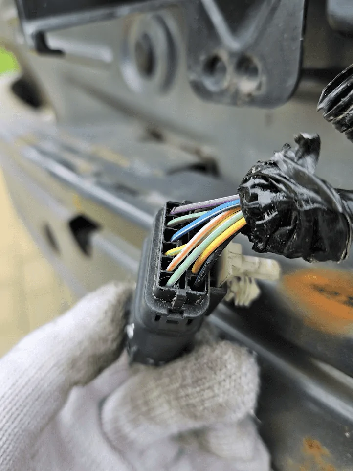
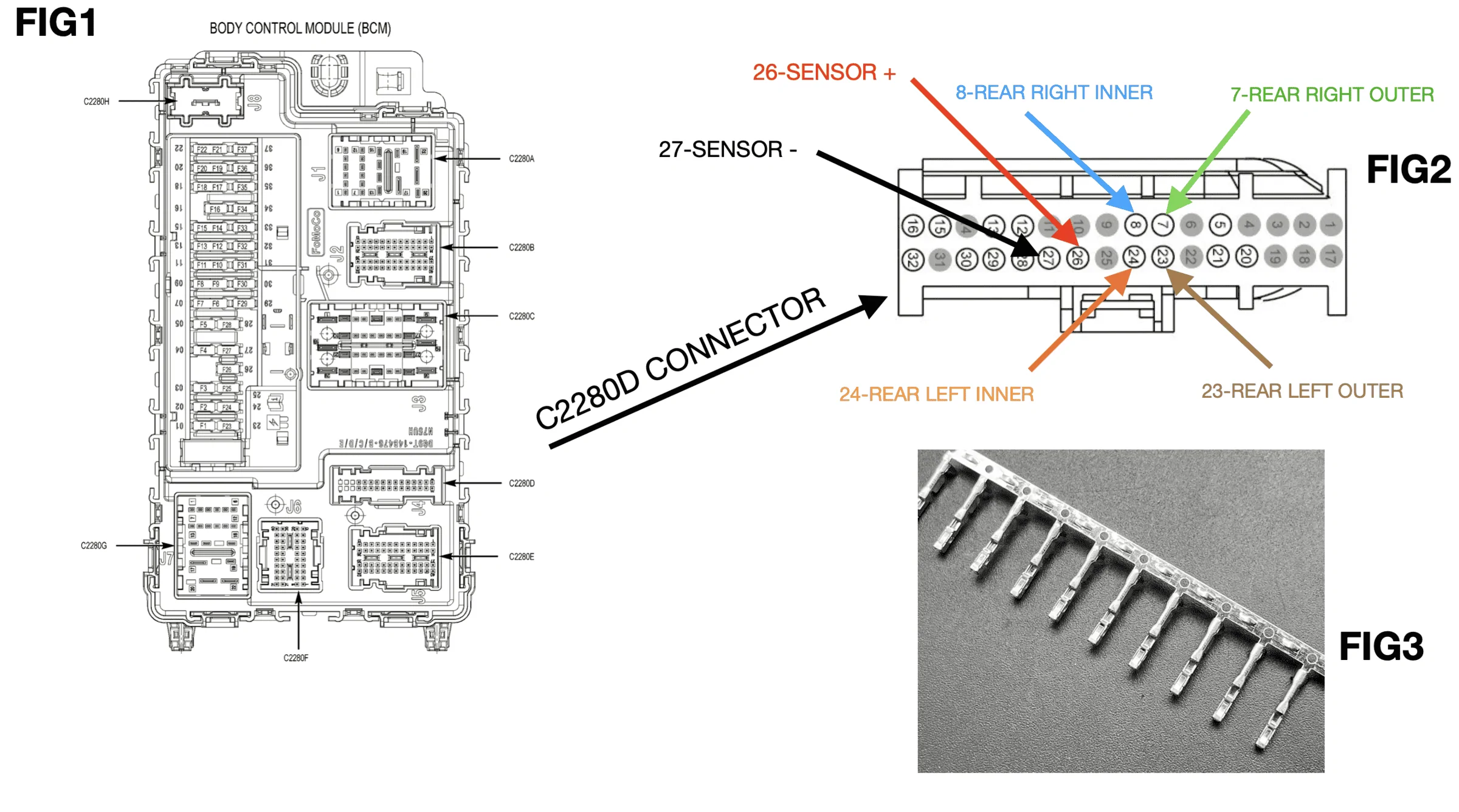
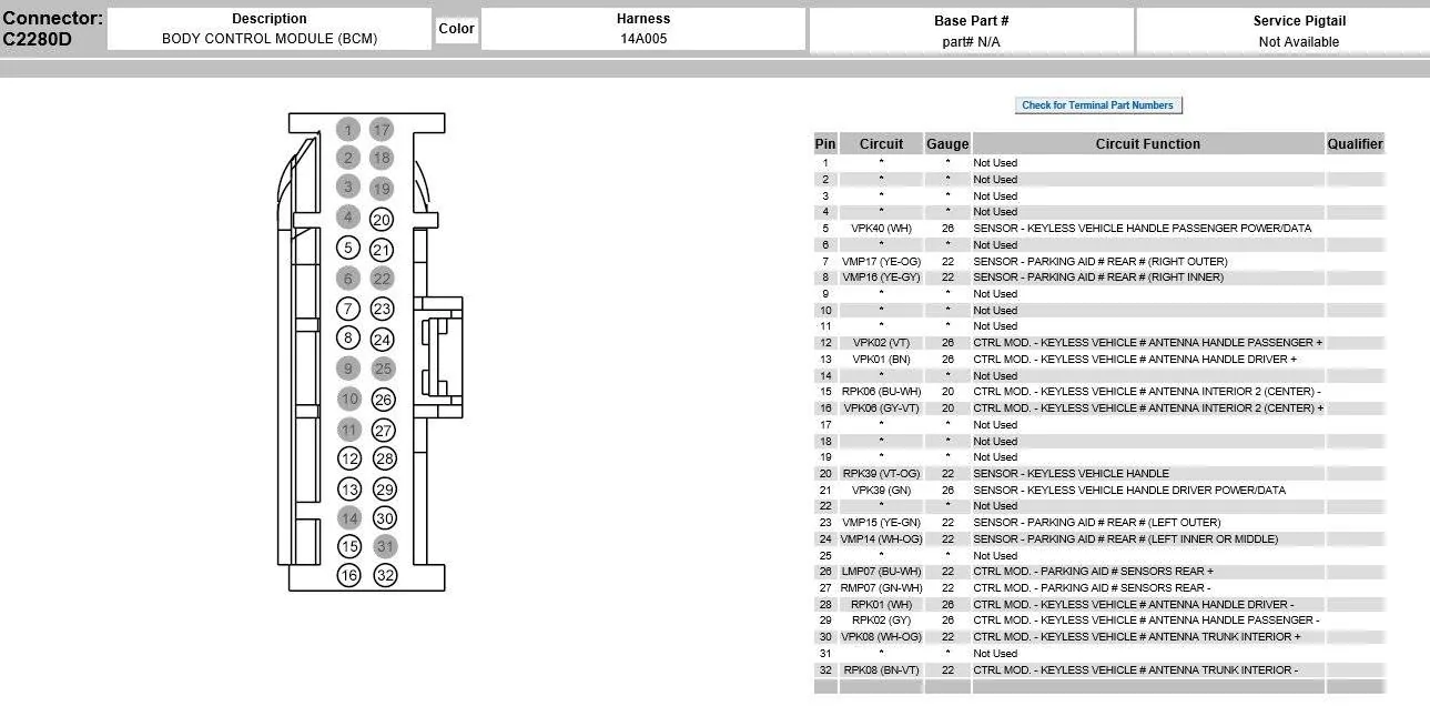
Hi friends, today I will show you how to add OEM parking sensors on basic Mustang. I own the 3.7 V6 model from 2015 and most of them don't have sensors, so I thought I'd put them on but initially I wasn't confident with online or in-store kits and wanted OEM Ford kits. I bought 4 used sensors with the initials: FR3T-15K859-AAW, fortunately they had the same body color. I also took the harness that connects the FR3T13412G281T sensors, it is located in the rear bumper and also connects the lights. Unfortunately, the wiring was not connected to any control unit, so I had to pass a 6-wire cable from the bumper to the BCM (fig1), which is located in the passenger compartment at the bottom right of the passenger side. At the end of the wires I put female DU2Z-14474-AA pins (fig3) that entered the C2280D connector (fig2).
1651254525336.png

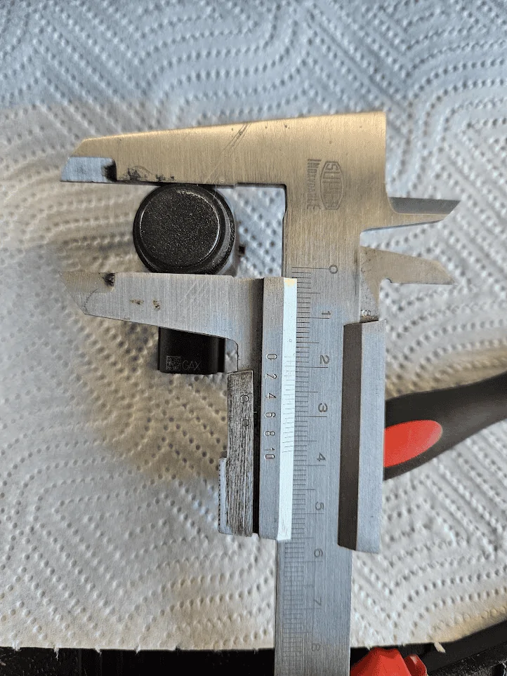
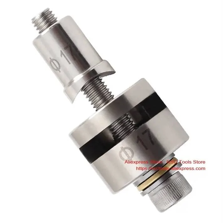
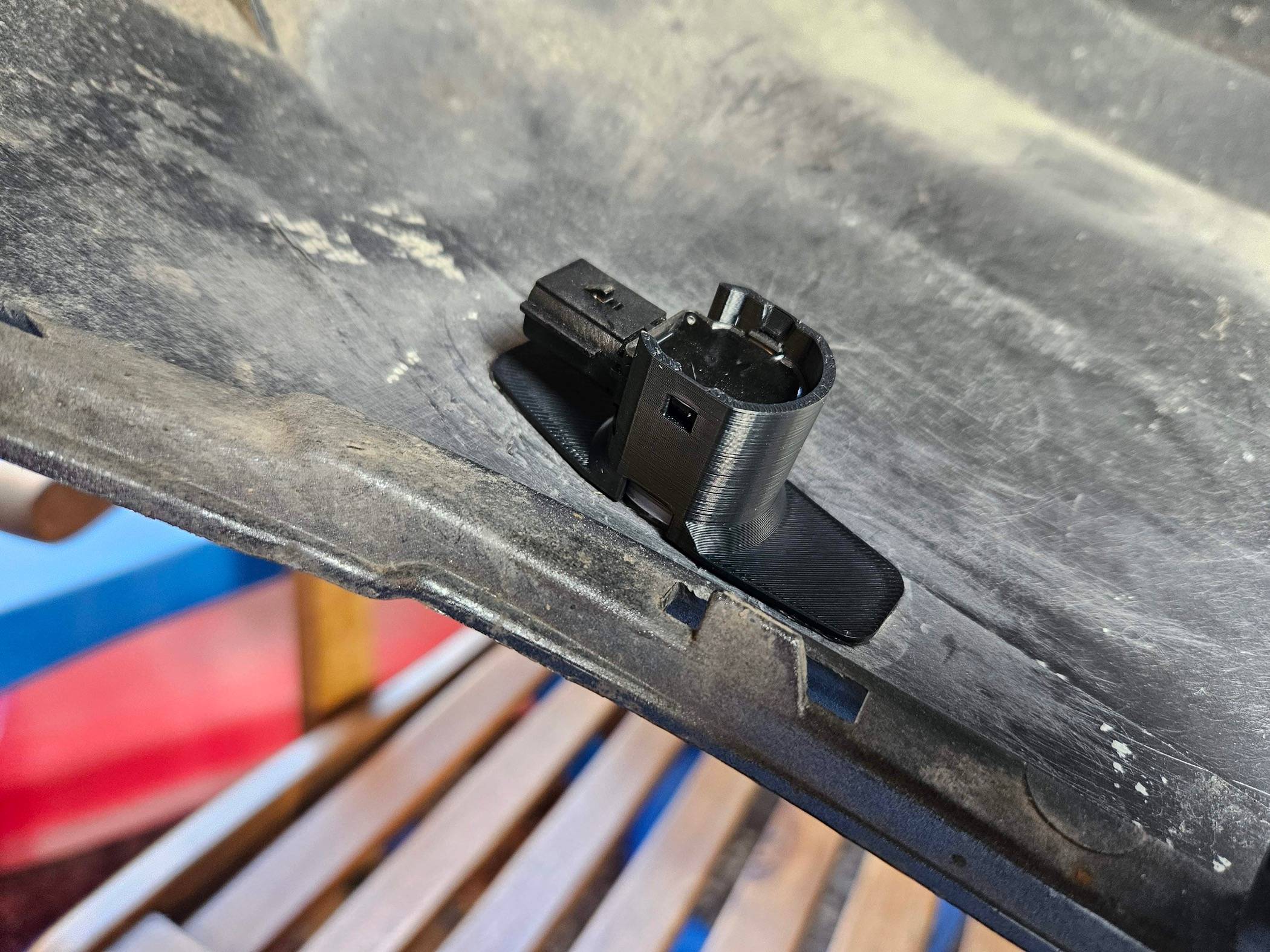
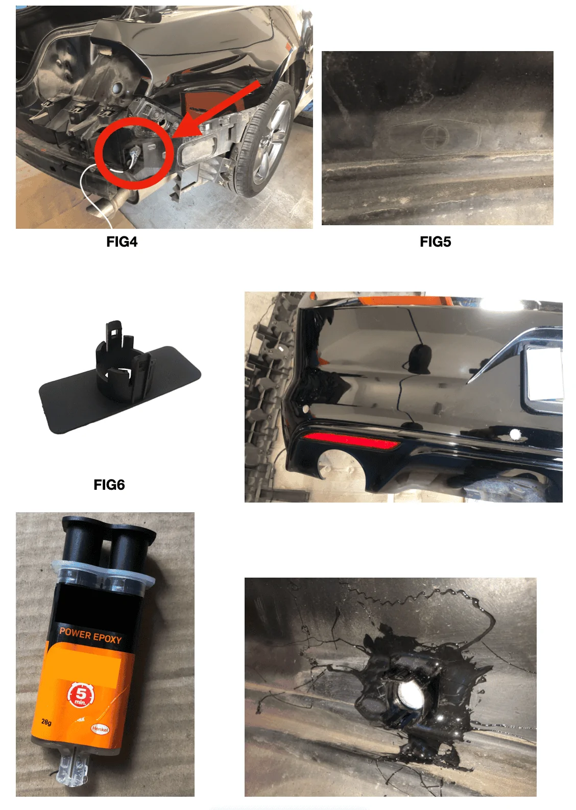
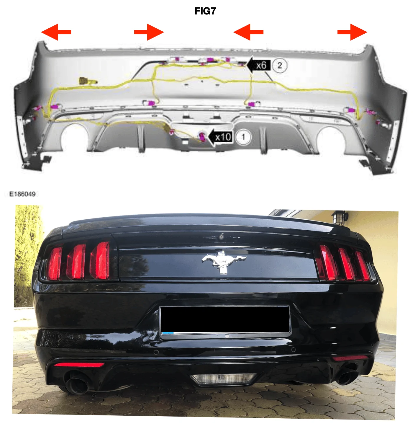
I disassembled the rear bumper and I took the 6-wire cable out (fig4), at this point I drilled with a 15mm bit to let the sensors in, there were already the marks where to make the hole (fig5) after which I glued the sensor supports with a bi-component glue (fig6). For correct operation, the sensors must be placed in the right position as in figure 7.Finally I connected the wiring as shown in the figure:

1651254587731.png

1651254622890.png

1651254643621.png

Now that the sensors have been applied and the wiring connected, the PAM control unit must be programmed. This module is already present on the BCM but it must be programmed to make it appear among the modules present. To do this, some AS BUILT parameters must be changed via Forscan and an ELM327 hs-ms switch.

On the BCM
726-46-02 xxxx xxx1 xxxx

On the IPC
720-02-02 5xxx xxxx


1651254812617.jpeg
Sponsored


Konamoth

Well-Known Member
Joined
Aug 10, 2021
Threads
4
Messages
359
Reaction score
353
Location
Atlanta, GA
First Name
Nick
Vehicle(s)
2020 Mustang GT Base
Huh. Pretty wild that one can even do that. Excellent write up. :like:
 

Magony15

Well-Known Member
Joined
Jun 11, 2016
Threads
0
Messages
85
Reaction score
53
Location
Northern Illinois
Vehicle(s)
2015 GTPP Base/Prem, 2009 Ram 1500
The toughest part is finding the sensor brackets. Ford doesn't sell them. Where did you find them?
 
OP
OP

already

Member
Joined
Mar 15, 2021
Threads
4
Messages
9
Reaction score
10
Location
Italy
Vehicle(s)
Mustang s550 3.7 v6 2016
I bought the sensor brackets on ebay for a price of 10 $ 4 pieces. initially I couldn't find the Ford ones but the BMW ones were compatible
 

rubens_5.0

Well-Known Member
Joined
Jun 17, 2019
Threads
5
Messages
123
Reaction score
22
Location
Los Angeles, CA
First Name
Ruben Rolon
Vehicle(s)
2016 Mustang GT PREMIUM PP ESS G3 SUPERCHARGED
I did this like 2 years ago but i had to buy the the a whole rear bumper with sensor holes as the brackets are on the bumper and ford doesn’t sell them separately. Good write up
 

Sponsored

mateusz85

New Member
Joined
Sep 15, 2022
Threads
0
Messages
1
Reaction score
1
Location
Poland
First Name
Mateusz
Vehicle(s)
17' 3.7l 6gen
Look great, but I have one question. I see that you have reverse camera, now you add parking aid. How It works together ? Do you see on screen what is on camera and hear in loudspeaker parking aids? Or just you can choose somehow what you would like to use ?
 

rubens_5.0

Well-Known Member
Joined
Jun 17, 2019
Threads
5
Messages
123
Reaction score
22
Location
Los Angeles, CA
First Name
Ruben Rolon
Vehicle(s)
2016 Mustang GT PREMIUM PP ESS G3 SUPERCHARGED
Little car with sensors pops up in reverse camera in the top right corner and you can turn off sensors in settings if you like
 

rubens_5.0

Well-Known Member
Joined
Jun 17, 2019
Threads
5
Messages
123
Reaction score
22
Location
Los Angeles, CA
First Name
Ruben Rolon
Vehicle(s)
2016 Mustang GT PREMIUM PP ESS G3 SUPERCHARGED
And yes you see on screen plus you do here it as well through speakers
 

Sponsored
OP
OP

already

Member
Joined
Mar 15, 2021
Threads
4
Messages
9
Reaction score
10
Location
Italy
Vehicle(s)
Mustang s550 3.7 v6 2016
hello, in the PAM module I put these As-built values:
736-01-01 4450 000B
736-02-01 0400 0400
736-03-01 0600 4200
736-04-01 0000 0000
736-05-01 0000 0000
 

Nightmonkey

Well-Known Member
Joined
May 12, 2022
Threads
3
Messages
801
Reaction score
1,224
Location
Germany
First Name
Jens
Vehicle(s)
2020 Bullitt
Does soneone know the BCM pins for the front parking aid?
Of course, this is not described in the workshop documents because it is not available from the factory.
However, at least two companies over here offer a retrofit with oem sensors and full Sync integration.
 

sergejbubko

New Member
Joined
Aug 21, 2023
Threads
0
Messages
1
Reaction score
4
Location
Czechia
First Name
Vaclav
Vehicle(s)
Mustang GT 2016 324 kW
First of all, I would like to thank @already for this topic. Without his description I wouldn't even start thinking about doing this myself. I had the same idea of not using other but OEM solution.

There are many variables you can struggle with and it is definitely not that easy as I thought. I would like to improve the first post with some findings I had during (still not working) parking aid on my Mustang 2016 GT Performance.
Edit: I had issues with sensors bought at local Ford dealer, so I ordered another set from Ali and it finally works like a charm. This is the set I bought (https://a.aliexpress.com/_ExcMzO9)

First of all, buying material in Europe, Czech republic could be tricky if you have US version of Mustang. Sensors mentioned by @already are perfectly fine for this project. However harness with item number FR3T-13412-G281T is general description and if you don't want to have headaches like I did you should find the one with right suffix:
Mustang versionPart #
USwithout sensorsFR3T-13412-G281T-Athis was on my car
USwith sensorsFR3Z-13412-G281T-Bthis is the one I needed
EUwith sensorsFR3T-13412-G281T-Dthis is the one I bought

I ended with original part from local Ford dealer and as it showed up it was meant for EU Mustang, which hasn't got side marker lamps and has combined backup lamp with fog lamp and thus different connector. I had to do some modifications which was time consuming and with uncertain result.

EU: FR3T-13412-G281T-D(B) without side marker lights connectors and different backup lamp
1694700042524.png


US: FR3Z-13412-G281T-B(C) with brown backup light connector and grey side marker connectors
1694700279256.png


On my Mustang I had all wires from BCM to rear bumper presented, so I didn't need to run a new wire for rear sensors. I suggest to check this first, before you purchase quite expensive cable and pins for this task. You can check the wiring in C2280D connector on passenger side or after you dismantle the rear bumper on the other side of the harness.
You can reach the BCM using this schema:
1694705620522.png

Wiring harness:
color codefunction
green w/ white stripe-
blue w/ white stripe+
yellow w/ orange striperight outer
yellow w/ green stripeleft outer
yellow w/ grey striperight inner
white w/ orange stripeleft inner
Which as I can see now corresponds to markings in @already C2280D schema.

C2280D connector with the necessary wires already present:
1694701651633.png


Rear end of this wire under bumper:
1694701804400.png


For disassembling the rear bumper I suggest and and

It is not necessary to remove the wheel, if you have small screwdriver with flexible shaft or smaller ratchet wrench with extension.

I am not sure if the sensors have different diameters but mine was 15.5 mm without rubber seal. With the rubber seal I had to use 18 mm drill bit to drill holes for sensors, 15 mm as @already mentioned didn't work for me, not even 16 mm as 15 mm is hard to find.

1694705103887.png


Edit: recently I found online this tool (https://a.aliexpress.com/_Evvhlq5) for punching holes into bumper. You can search for “parking sensor hole punch tool”. Although It is quite expensive and you need to know exact size, I would definitely use this next time for more precise cut instead of using cheaper stepped drill bit. I would use 18 or 17.5 mm in my case.
IMG_0434.jpeg


Sensor mount/bracket/holder
I decided to design and print my own sensor mounts from ASA. I had some gluing problems. Acetone didn't work as I expected (I am not sure if the bumper is made of ABS which is suitable for cold welding with acetone edit: I am sure It is not, it should be some mix of polycarbonate and some other plastics) so I ended also with bicomponent epoxy glue. I put the sensors into mounts, put some epoxy glue on mounts and center them into drilled holes to be sure the mounts are on right position.
Edit: epoxy worked, but wasn’t as reliable as I wanted. 3D printed ASA mounts just pealed off using a little force. I made version 2.0 of mounts with stronger construction (similar to OEM) and printed them on my new Bambulab P1S with black ASA. The quality is much better. I used double sided tape instead (Ceys Montack - as 3M is not very common in our shops).

Original version printed from Signal white Prusament ASA on Ender 3V2: sensor can be mounted both directions, however sides were breaking apart probably due to poor printing quality from Ender with stock hotend. You can try print it yourself here https://makerworld.com/en/models/77252#profileId-81625:
20230909_113241_.jpg


Version v2 with more OEM like design and sturdier but only with one direction sensor mount option: printed from Eryone3D black ASA on Bambulab P1S, model can be found here: https://makerworld.com/en/models/384830#profileId-285088:
20240314_163000_Original.jpeg


Programming
I had many problems in the programming part, so I would like to expand this part as well
  1. Using forscan activate PAM module
    BCM Park Aid: 726-46-02 xxxx xxx1 xxxx Park Aid Feature Present
  2. Once complete, reconnect to your vehicle using forscan with a new profile. The PAM module will now appear. It will be loaded with a totally incorrect set of config that will cause various DTCs, load one appropriate to your vehicle and its off.
    For my car I had these PAM values, but it may differ to yours.
    PAM:
    736-01-01 4440 000B 2 Door, 4 CH (4 sensors), EF Gasoline, GT Manual, Left hand
    736-02-01 0400 0400
    736-03-01 0600 4200
    736-04-01 0000 0000
    736-05-01 0000 0000
  3. Next is IPC:
    720-02-02 1Axx xxxx (1) Park Aid Enabled + (A) PEPS enabled, PLC disabled, PS enabled, LC Non-DNA
    720-04-02 xxxx x2xx Park Aid Fault Warning Rear and Front enabled
  4. Next up is to enable park assist and the correct sensors in your APIM
    APIM:
    7D0-01-01 xAxx xxxx xxxx A=PDC HMI Enabled, RVC Present, Illumination FNA
    7D0-02-01 xxxx xxx2 xxxx Vehicle Style (VS) in Camera Views Convertible/Coupe
    7D0-04-02 xx01 xx Parking Distance Control (PDC)/Parking Assistance (PA): Active Park Assist (APA) / Park Out Assist (POA) / Perpendicular Park Assist (PPA) / Semi-Auto Parallel Park Assist (SAPP) 01=Rear PDC (4 Sensors)
    7D0-02-02 xxxx 8xxx 8=DS On, RSS Not Present, PDCA CGEA 1.3, TCU Not Present

List of all codes can be found in FORScan 2015-2020 F150s - Livnitup or in my copy of relevant codes for parking aid.
 
Last edited:

asci01

Well-Known Member
Joined
Jun 4, 2018
Threads
2
Messages
55
Reaction score
13
Location
FL
Vehicle(s)
2015 Mustang GT Premium 50th Anniversary & 50 LE
Another successful installation, Thank you 'already' and 'sergejbubko' for your write up and advice. Just a few notes to add more detail.


OEM wire colorFunctionPin # at the rear bumper connector (C405)Pin # at sensor
Color
I used at sensor
Pin # at the BCM connector (C2280D)
Yellow with orange stripe​
right outer signal​
112
Brown​
7
Yellow with gray stripe​
right inner signal​
102
Purple​
8
Green witth white strpe​
- VDC63
Green​
27
White with orange stripe​
left inner signal​
52
White​
24
Yellow with green stripe​
left outer signal​
42
Yellow​
23
Blue with white stripe​
+ VDC31
Blue​
26

If you want to know if you have the harness on the rear bumper with the wires for the sensors without removing the rear bumper, check the connector at the BCM (C2280D). If you have 17 wires, then six of those wires go the the plug on the rear bumper for the sensors (4 for each sensor signal, one +VDC (shared by all the sensors) and one -VDC also shared by all 4 sensors.
 

asci01

Well-Known Member
Joined
Jun 4, 2018
Threads
2
Messages
55
Reaction score
13
Location
FL
Vehicle(s)
2015 Mustang GT Premium 50th Anniversary & 50 LE
My OEM sensors were 17mm in diameter including the rubber ring around them but since the hole needs to be exact for obvious reasons, I used a STEPLESS drill bit from Harbor Freight (SKU 66463) which allowed me to drill the hole (the location is already marked on the bumper) to the exact diameter. Even 1/8 of a mm makes a big difference.

With the sensor connector facing upward and looking at the rear of it, Pin 1 (+VDC) will always be at the right most end, while Pin 3 (-VDC) will always be at the left most end. Pin 2 (sensor signal) is always the middle one. Keep this in mind since the sensors' ends point in different directions.
Sponsored

 
Last edited:


Top