Mishimoto
Well-Known Member
- Thread starter
- #1
UPDATE:
Hey guys,
As noted on several other threads here on Mustang6g, we are hard at work to develop an awesome intercooler. Follow the progress of development on our blog, or posted in this thread!
http://engineering.mishimoto.com/category/ford-mustang-2-3l-ecoboost-intercooler-2015/
The Mustang EcoBoost Intercooler, Part 1: Stock Cooler
With nearly a 30-year gap between the old and new turbocharged 4-cylinder Mustang, some things are bound to change. The new Mustang features many interesting advances in technology, including direct injection, a twin-scroll turbocharger, a DOHC cylinder head with variable valve timing, and a newly designed intercooler. The 80’s model featured a top-mount intercooler that was fed cool air through a functional hood scoop. This was pretty slick stuff for the days when the Walkman revolutionized how we listen to music, and “the Clapper” paved the way for a new level of laziness.
The new Mustang features a very efficient front-mounted intercooler that fits right below the radiator. A fresh stream of airflow passes through the tube-and-fin core and works to combat high intake temperatures.
We’ve been highlighting our progress on the development of a variety of new components for the 15’ Mustang, and it’s finally time to get caught up on our intercooler design! Follow our progress below.
Stock Intercooler Design
Before jumping into the new cooler design, let’s took a look at the stock intercooler and its location. This would give us a good idea of where improvements can be made.
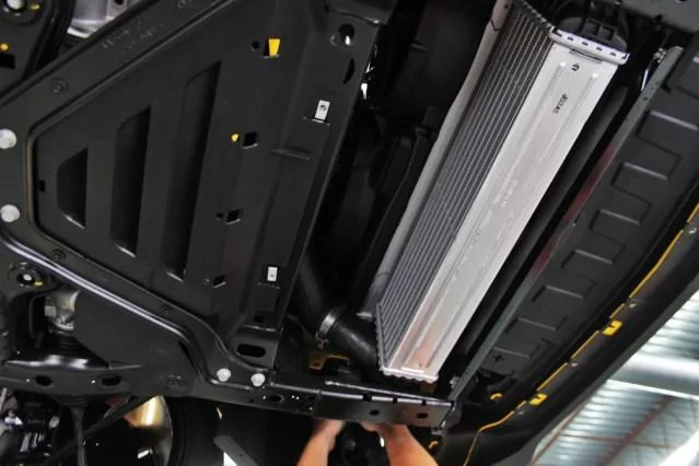
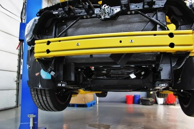
Here are a few shots of the stock cooler in its proper position.

Stock intercooler installed

Stock intercooler installed
Stock intercooler installed
Next, we stripped the stock setup from our test vehicle!
Stock intercooler removed
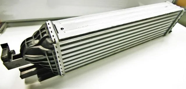
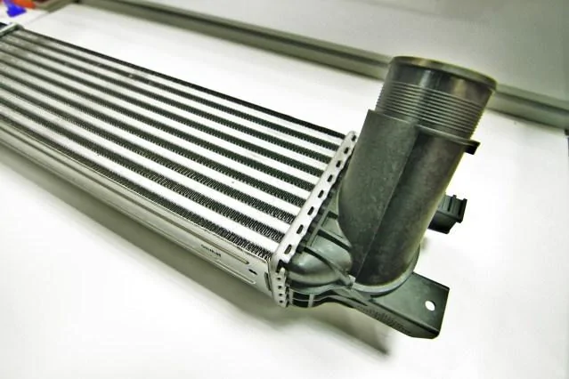
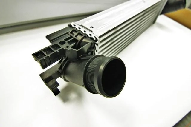
Once removed, we took a closer look at what Ford provided with the EcoBoost Mustang.
Stock intercooler

Stock intercooler
Stock intercooler
Stock intercooler
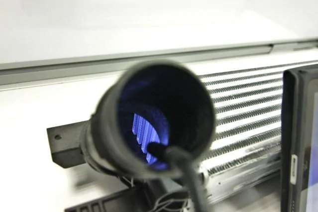
The exterior fins are reasonably dense on this stock cooler. We then took a peek at the internal fins.
Stock intercooler internal fins
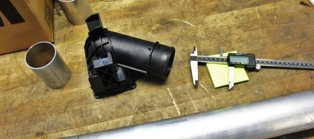
We planned to pull this unit apart for further inspection, but first we grabbed a few of the dimensions using our Romer arm. This would help us plan a few of the mounting points and general constraints once we get to the point of designing our cooler.

Obtaining stock intercooler dimensions via coordinate measuring machine
Stock Intercooler Internals
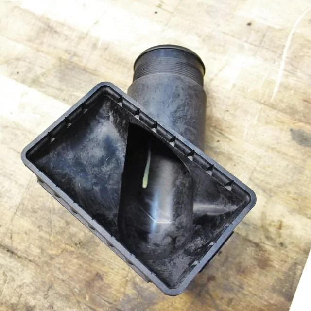
Now that the measuring was complete, off with the end tanks! These are removed easily by bending the crimped edges. The plastic tanks seal to the core with a rubber gasket.

Stock intercooler end tank removed

Stock intercooler end tank internal surface
We were then left with a bare core!

Stock intercooler core
Stock intercooler core
We then snagged basic core dimensions!

Stock intercooler core dimensions
Let’s quickly recap our findings on the stock cooler and outline our plans for the Mishimoto unit.
Stock Intercooler
As we proceed with development, is there anything specifically that you’d like to see highlighted in these posts?
Thanks
Project Update! Check it out below.
The Mustang EcoBoost Intercooler, Part 4: Final Prototype Design
Prototype Modeling
Now that we had a core that was functioning to our standards, it was time to finalize our end tank design and make 3D models to reflect our plans. After some lengthy modeling work, we came up with the renders you see below!

Mishimoto prototype intercooler 3D model
Mishimoto prototype intercooler 3D model
Mishimoto prototype intercooler 3D model
A few quick notes about this cooler! We designed this unit to fit within the same space as the stock intercooler. We designed cast-aluminum end tanks, which will be mated to the bar-and-plate core we tested during the previous (Part 3) segment of this series. We are also retaining the stock intercooler connections, which are large enough for sufficient flow to produce rather high power.
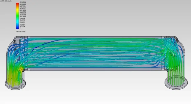
For this cooler we were concerned with pushing air to the entire thickness of the cooler. During the design of this cooler we experimented with internal end tank diverters. We’ve used these diverters on a few of our taller coolers to help promote airflow to the full length of the intercooler. By doing so we can take full advantage of the large core.
First, check out the dispersion of air without any internal diverter, as demonstrated by computational fluis dynamics (CFD).
CFD of air dispersion in Mishimoto prototype intercooler without a diverter
And the shot below shows the dispersion with a diverter installed.

CFD of air dispersion in Mishimoto prototype intercooler with a diverter
As you can see, the diverter placement is making a fairly significant impact on the air dispersion to the rear of the cooler. We decided this was the route to go, and we will be including this feature on our next prototype. It will be very interesting to see the impact of this change on the outlet temperatures.
Here is a look at a 3D model cutaway showing the diverter.
Internal air diverter 3D model
Internal air diverter 3D model
3D-Printed Prototype
To verify fitment, we 3D-printed our end tanks to obtain the exact dimensions of our design so we could fit this to the vehicle and ensure that we were spot-on.
First, the tanks were printed.
3D-printing of prototype end tank
And the result!
3D-printed prototype of end tanks
3D-printed prototype of end tanks
3D-printed prototype of end tanks
3D-printed prototype of end tank
Once printed, we attached these to a prototype core and mocked up the unit into place to confirm all our dimensions and mounting points.
Check back next time for a look at our fully functioning final prototype!
Thanks
-John


Hey guys,
As noted on several other threads here on Mustang6g, we are hard at work to develop an awesome intercooler. Follow the progress of development on our blog, or posted in this thread!
http://engineering.mishimoto.com/category/ford-mustang-2-3l-ecoboost-intercooler-2015/
The Mustang EcoBoost Intercooler, Part 1: Stock Cooler
With nearly a 30-year gap between the old and new turbocharged 4-cylinder Mustang, some things are bound to change. The new Mustang features many interesting advances in technology, including direct injection, a twin-scroll turbocharger, a DOHC cylinder head with variable valve timing, and a newly designed intercooler. The 80’s model featured a top-mount intercooler that was fed cool air through a functional hood scoop. This was pretty slick stuff for the days when the Walkman revolutionized how we listen to music, and “the Clapper” paved the way for a new level of laziness.
The new Mustang features a very efficient front-mounted intercooler that fits right below the radiator. A fresh stream of airflow passes through the tube-and-fin core and works to combat high intake temperatures.
We’ve been highlighting our progress on the development of a variety of new components for the 15’ Mustang, and it’s finally time to get caught up on our intercooler design! Follow our progress below.
Stock Intercooler Design
Before jumping into the new cooler design, let’s took a look at the stock intercooler and its location. This would give us a good idea of where improvements can be made.
Here are a few shots of the stock cooler in its proper position.

Stock intercooler installed
Stock intercooler installed

Stock intercooler installed
Next, we stripped the stock setup from our test vehicle!
Stock intercooler removed
Once removed, we took a closer look at what Ford provided with the EcoBoost Mustang.

Stock intercooler
Stock intercooler
Stock intercooler
Stock intercooler
The exterior fins are reasonably dense on this stock cooler. We then took a peek at the internal fins.
Stock intercooler internal fins
We planned to pull this unit apart for further inspection, but first we grabbed a few of the dimensions using our Romer arm. This would help us plan a few of the mounting points and general constraints once we get to the point of designing our cooler.

Obtaining stock intercooler dimensions via coordinate measuring machine
Stock Intercooler Internals
Now that the measuring was complete, off with the end tanks! These are removed easily by bending the crimped edges. The plastic tanks seal to the core with a rubber gasket.
Stock intercooler end tank removed
Stock intercooler end tank internal surface
We were then left with a bare core!

Stock intercooler core

Stock intercooler core
We then snagged basic core dimensions!

Stock intercooler core dimensions
Let’s quickly recap our findings on the stock cooler and outline our plans for the Mishimoto unit.
Stock Intercooler
- Measures 20.5” x 5.75” x 3.2” for a total core volume of approximately 380 cubic inches
- Tube-and-fin core design
- Plastic end tanks crimped to the intercooler core
- Clamped hose connections on both inlet and outlet
- Fits in place under the radiator
- Features tank-mounted Manifold Absolute Pressure (MAP) sensor
- Increase volume substantially with a 4+” thick core
- Cast aluminum end tanks for increased durability and smooth flow
- Bar-and-plate intercooler core
- Direct fit including all piping connections
- Fit in the stock location without blocking airflow to radiator
- Retain the factory active grille-shutter system
- Improve horsepower and lower the intake temperatures
As we proceed with development, is there anything specifically that you’d like to see highlighted in these posts?
Thanks
Sponsored
Last edited:
