mejohn50
Intergalactic Snail
- Joined
- Jun 12, 2016
- Threads
- 24
- Messages
- 879
- Reaction score
- 1,065
- Location
- United States
- First Name
- Mitch
- Vehicle(s)
- slow junk
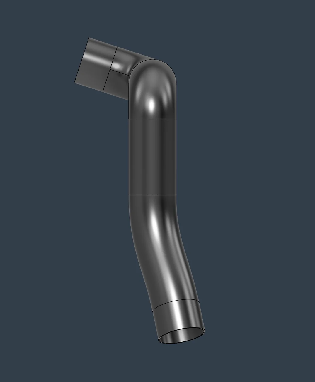
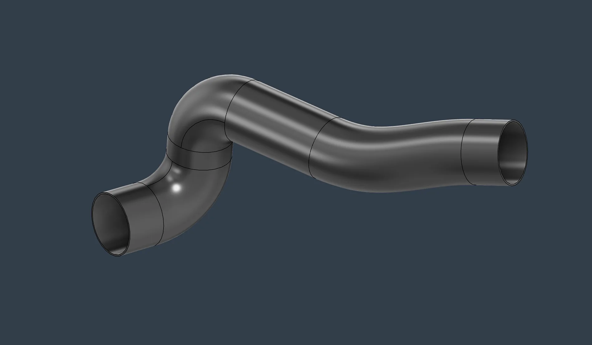
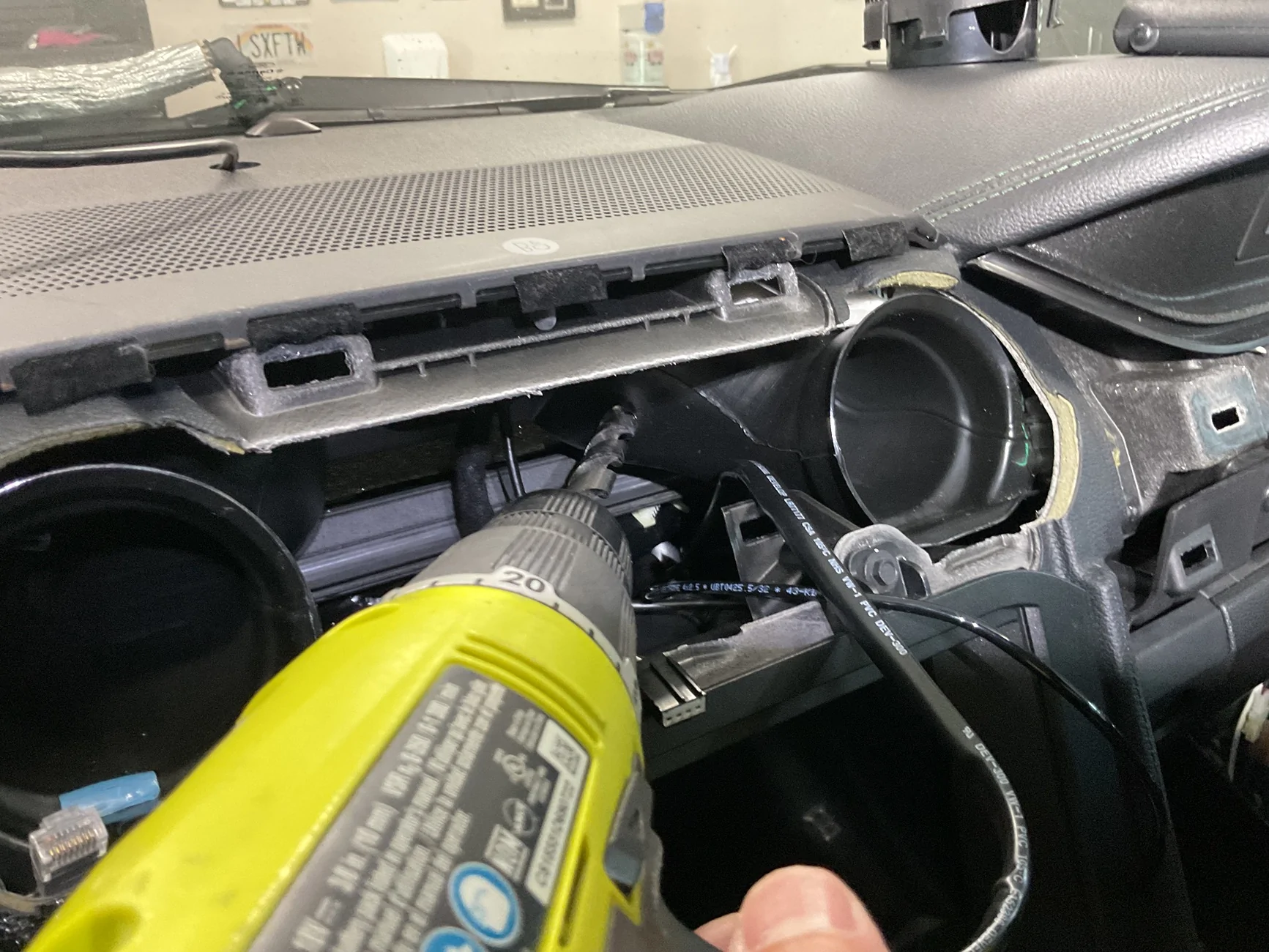
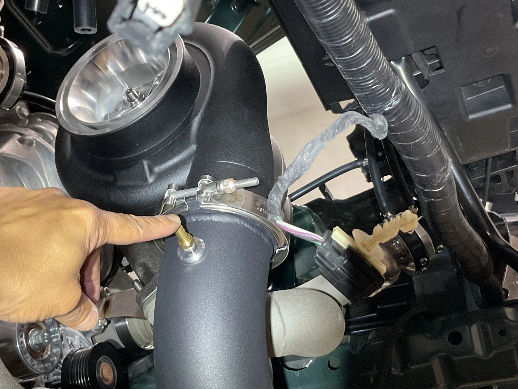
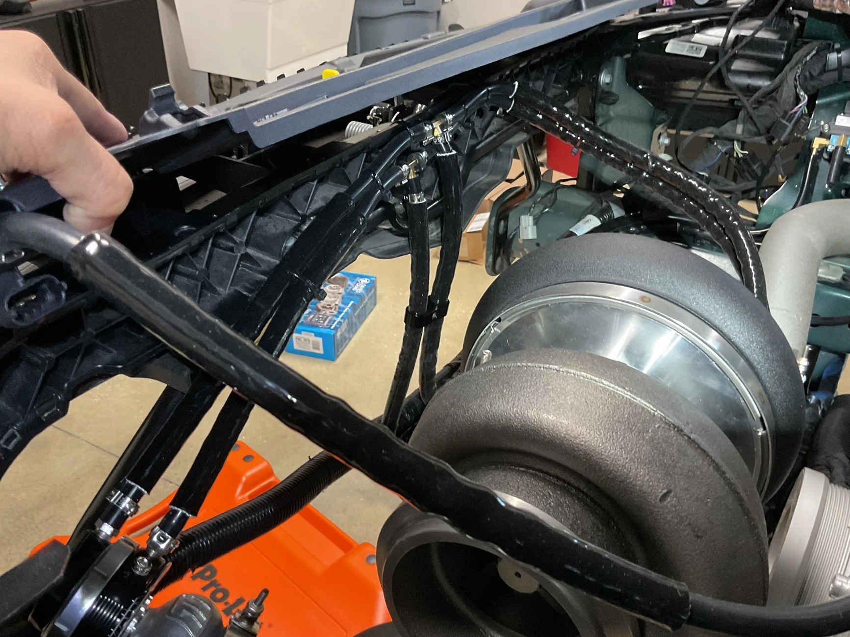
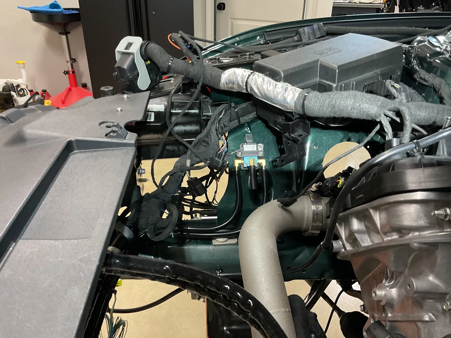
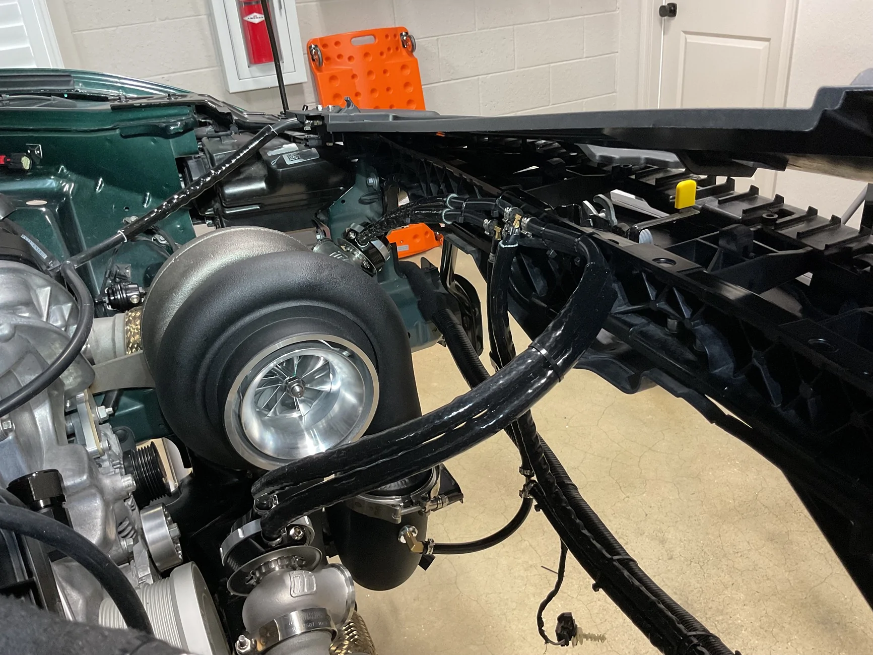
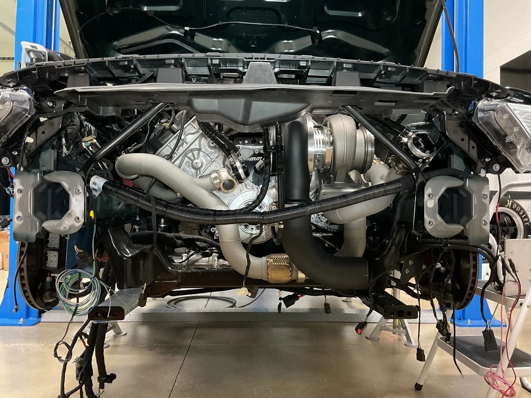
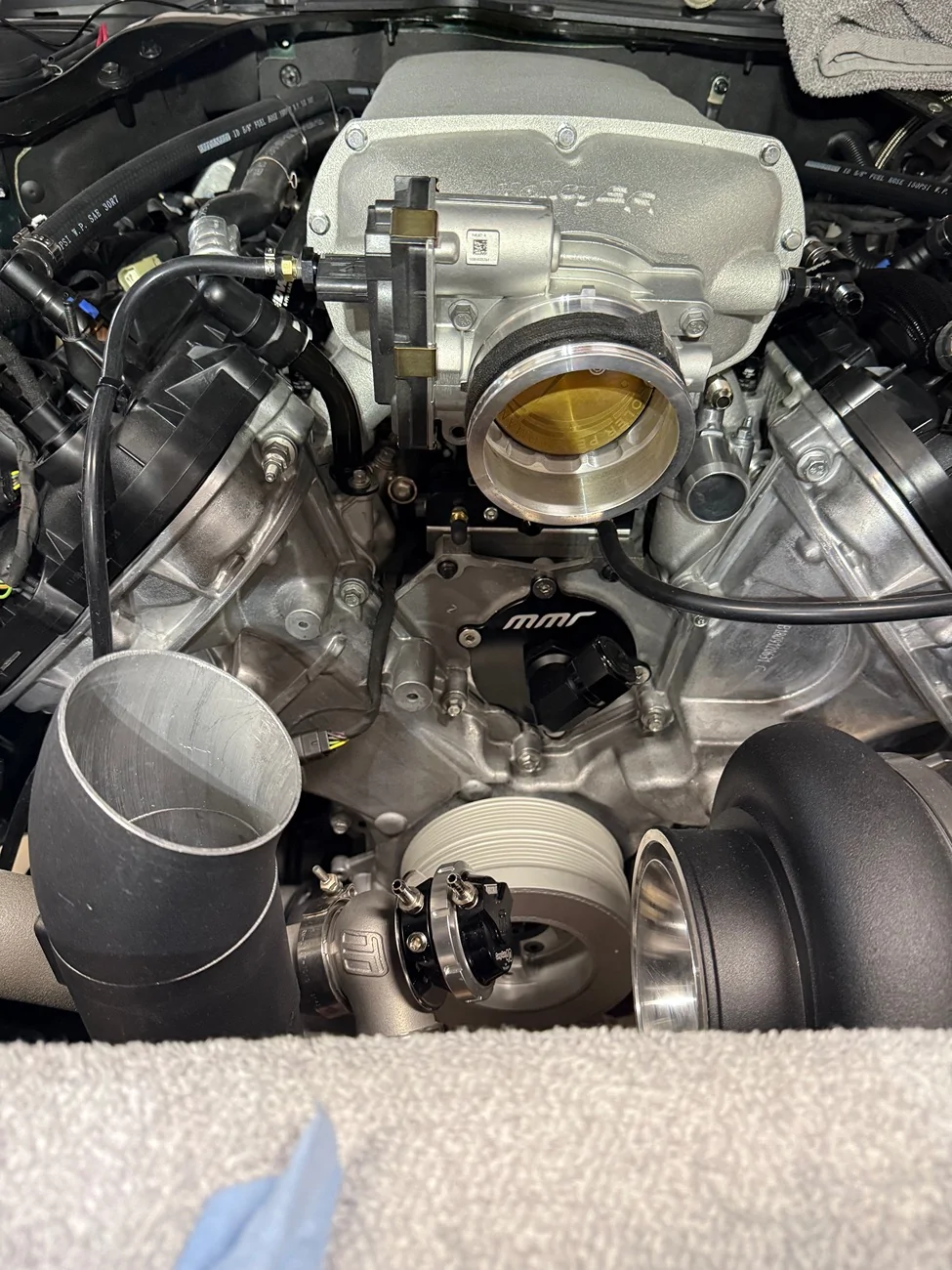
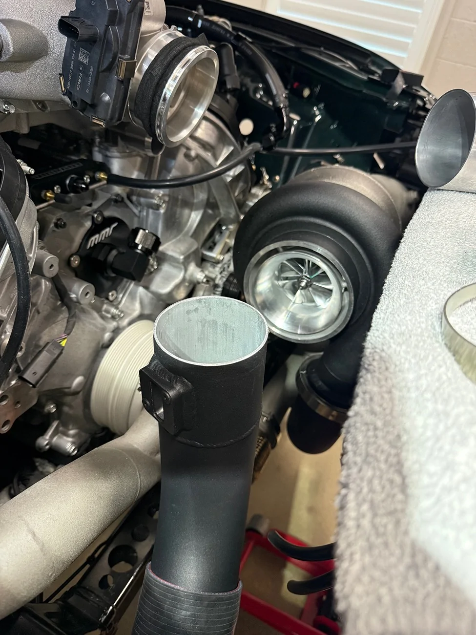
Take this for what it’s worth, but I’d 3D scan the engine bay, design exactly what I need in CAD, and just have the whole pipe from that lower silicone coupler to the TB 3D printed out of metal. You can even design in the flange for that coupler at the TB and have it printed right on the pipe.I spent all day making crude cuts to my charge pipe and some spare 3.5” aluminum pipe with a little 7” circular saw. I had to remove the fence/guide in order to make the cuts, which meant that I had to hold the pipe and carefully rotate it 360* to score them straight and then come back with multiple slow passes to cut through. Not fun at all, not to mention dangerous. A couple of times the blade bit too deep, too fast and tried to grab the pipe.
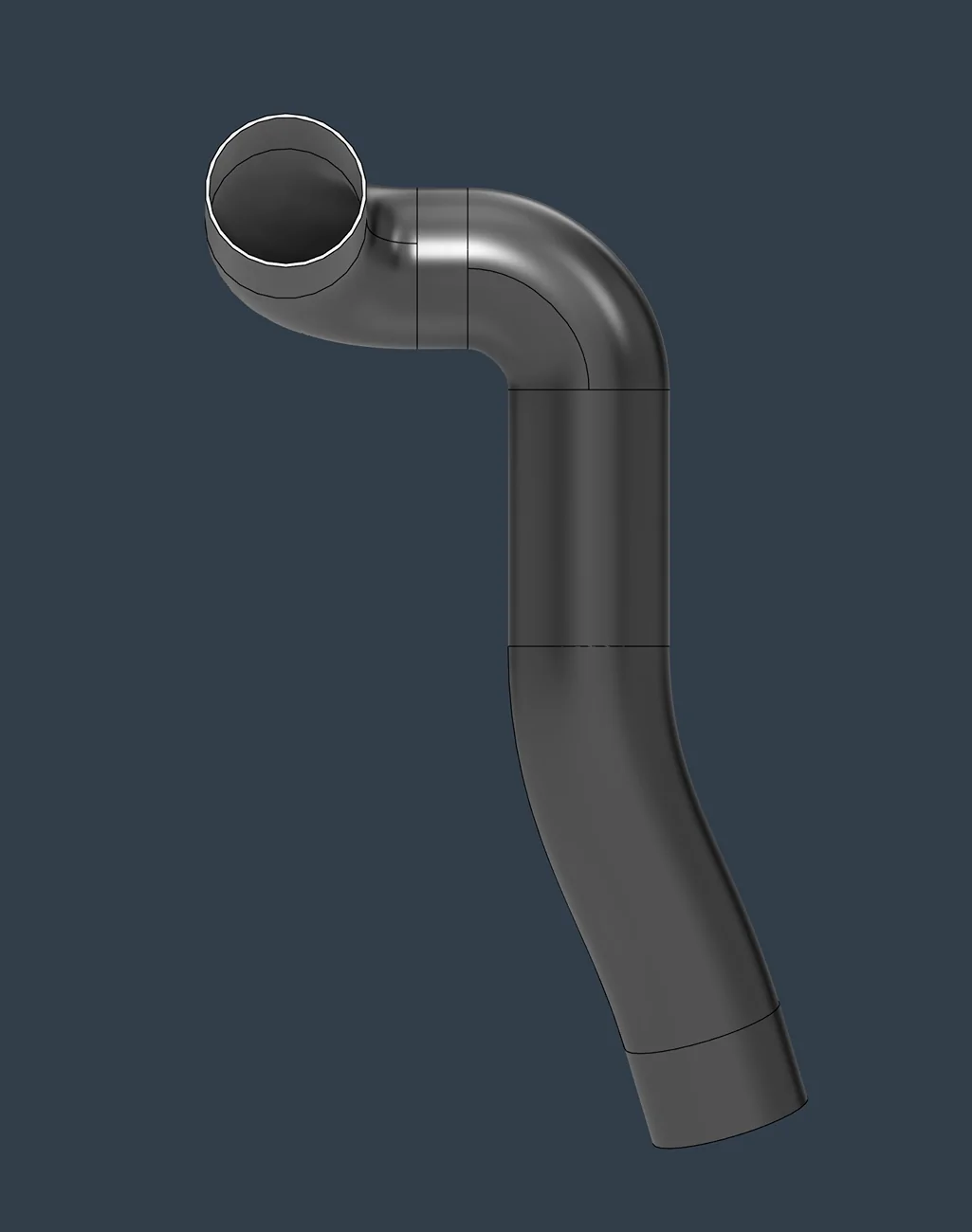
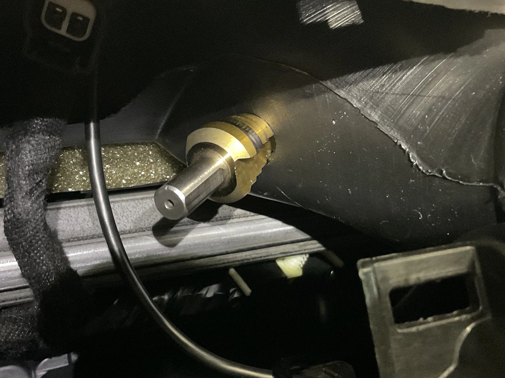
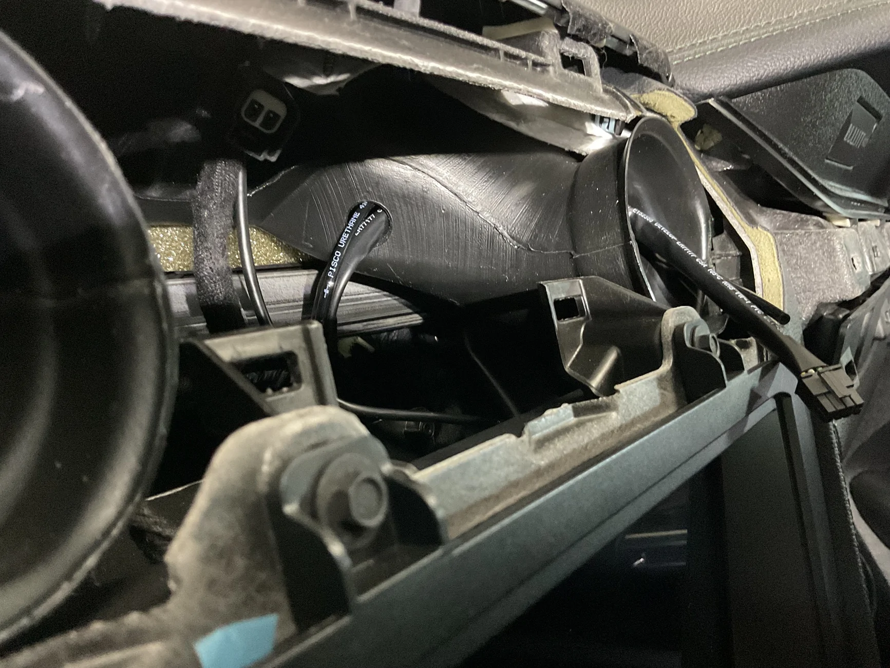
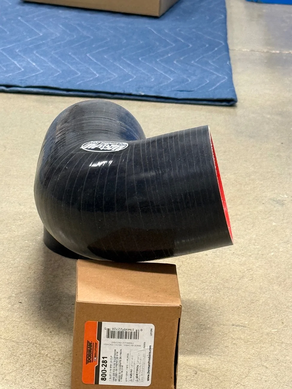
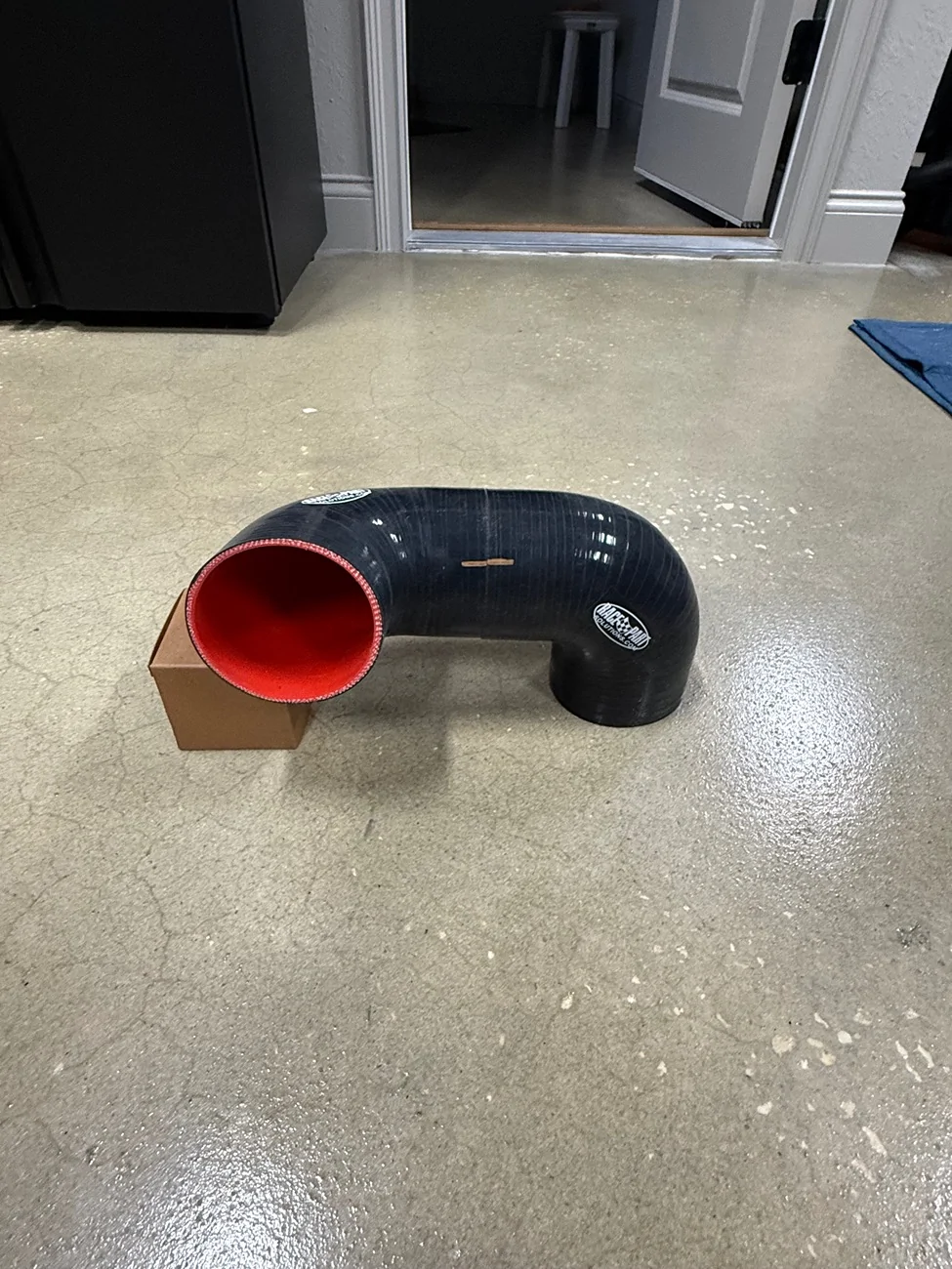
Moving on, I wasted a new 90* section of 3.5” aluminum pipe trying to get the angles right. In the end, it came down to using two 90* silicone couplers to get the exact angle of 72*, which is the angle on the Holley Lo Ram intake snout.
The silicone couplers have a tight 90* bend, whereas the aluminum 90* pipe has a looser bend.
The silicone couplers are just a mock up btw, but I would like to replicate this to get things perfect.
One of these days I’m gonna have to learn to weld. A good mill and lathe would also be nice to have.


Sponsored
 .
.