iiSLAyyer
New Member
- Thread starter
- #1
Has anyone out there installed the N2MB WOT box, using the Plug and Play/Upgraded harness, by The Gauge Mount?
No visual instructions, just written out saying to:
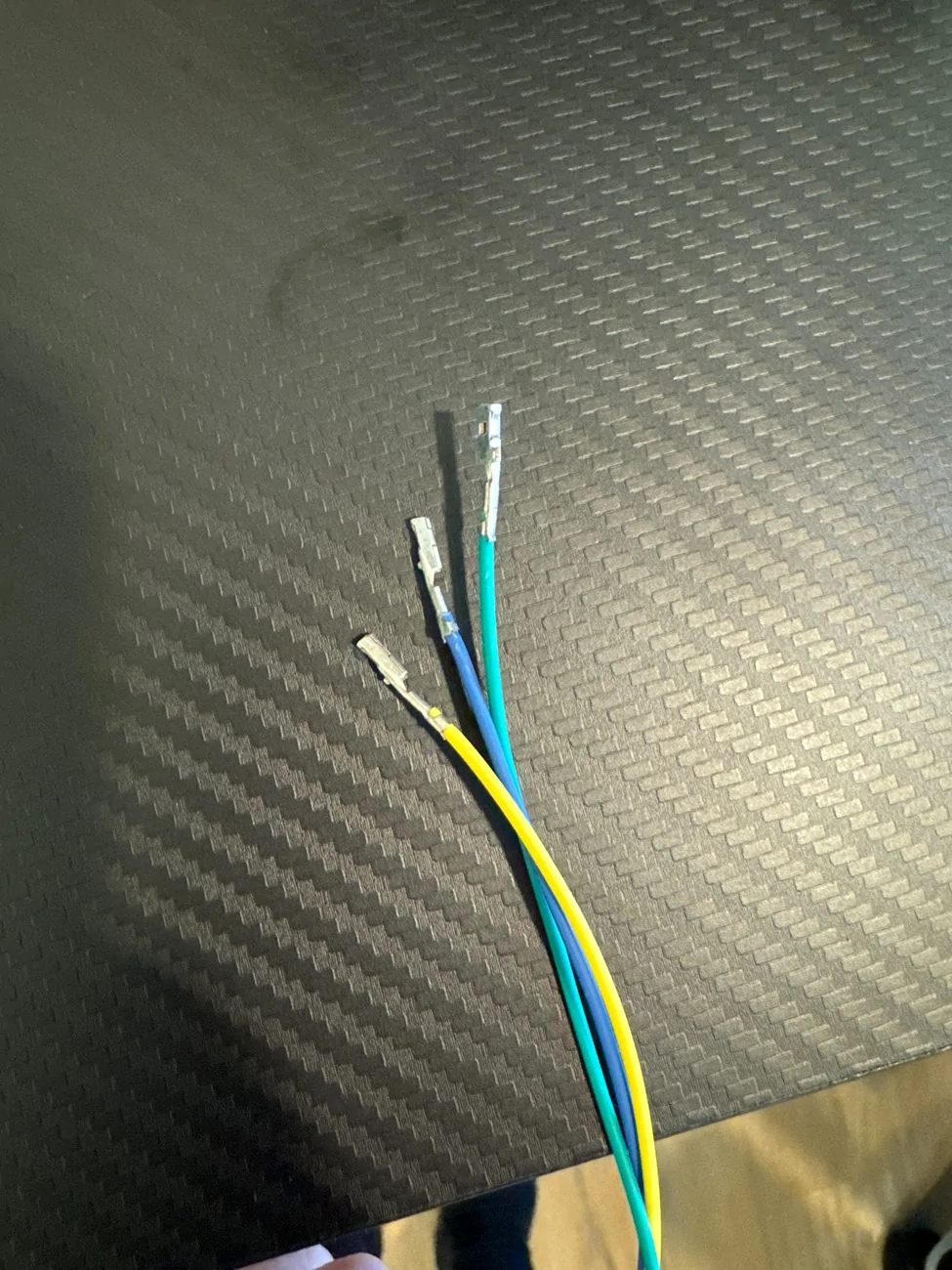
"De-Pin TPS, crank signal and clutch signal. Those wires go into the new connector bodies provided and need to match up to appropriate wires in male pin connectors on the N2MB Harness.
The female bare pin on each wire goes into corresponding location in ecu connector. Blue wire goes into TPS wire location, etc"
Wanting to verify steps
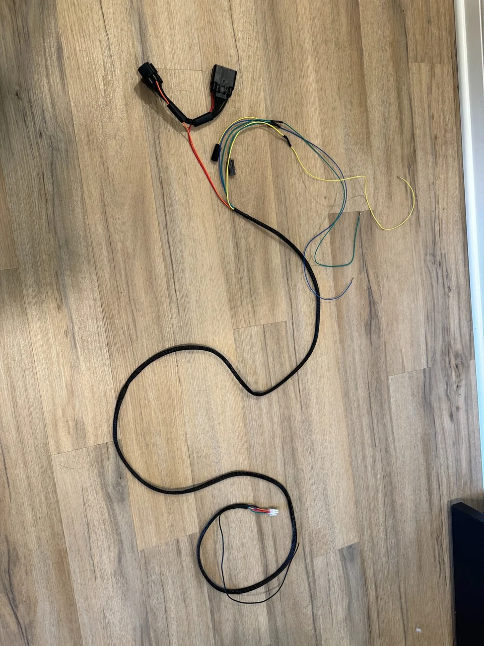
Here is the overview of the upgraded harness

1. Disconnect battery
2. Run cables through grommet in fender well
For 2019 and newer Manual Transmission cars:
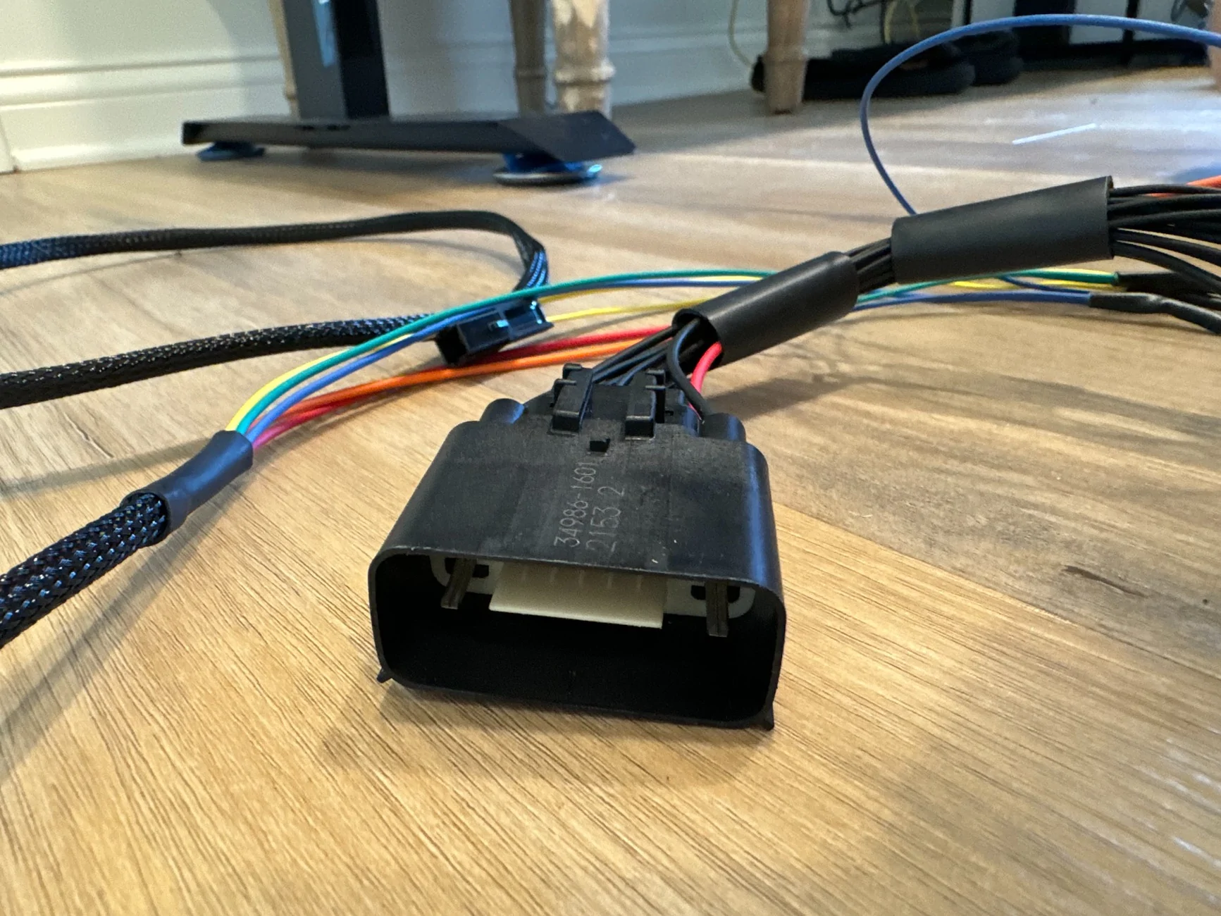
3. De-pin Yellow/Blue wire at pin #40 of the top ECU Connector (C175T)
4. Connect de-pinned Yellow/Blue to New Green Connector (male pin within new small black connector)
5. Connect Green female bare pin to pin #40 of top ECU Connector
6. De-pin Blue wire with White stripe at pin #68
7. Connect de-pinned Blue/White Stripe to New Blue Connector (male pin within new small black connector)
8. Connect Blue female bare pin to pin #68 of top ECU Connector
9. De-pin Yellow wire with Violet Stripe at pin #78 on middle ECU (C175E)
10. Connect de-pinned Yellow/Violet Stripe to New Yellow Connector (male pin within new small black connector)
11. Connect Yellow female bare pin to pin #78 of middle ECU Connector

Here's where I'm guessing a bit more with the Red/Orange connectors...
Red & Orange wires have their own New Connectors
12. Disconnect Coil Control Connector?
13. Place Red & Orange Connector in between Coil Control Connectors?
14. Install Ground wire
15. Reconnect battery
16. Install WOTBOX software
No visual instructions, just written out saying to:
"De-Pin TPS, crank signal and clutch signal. Those wires go into the new connector bodies provided and need to match up to appropriate wires in male pin connectors on the N2MB Harness.
The female bare pin on each wire goes into corresponding location in ecu connector. Blue wire goes into TPS wire location, etc"
Wanting to verify steps
Here is the overview of the upgraded harness
1. Disconnect battery
2. Run cables through grommet in fender well
For 2019 and newer Manual Transmission cars:
3. De-pin Yellow/Blue wire at pin #40 of the top ECU Connector (C175T)
4. Connect de-pinned Yellow/Blue to New Green Connector (male pin within new small black connector)
5. Connect Green female bare pin to pin #40 of top ECU Connector
6. De-pin Blue wire with White stripe at pin #68
7. Connect de-pinned Blue/White Stripe to New Blue Connector (male pin within new small black connector)
8. Connect Blue female bare pin to pin #68 of top ECU Connector
9. De-pin Yellow wire with Violet Stripe at pin #78 on middle ECU (C175E)
10. Connect de-pinned Yellow/Violet Stripe to New Yellow Connector (male pin within new small black connector)
11. Connect Yellow female bare pin to pin #78 of middle ECU Connector

Here's where I'm guessing a bit more with the Red/Orange connectors...
Red & Orange wires have their own New Connectors
12. Disconnect Coil Control Connector?
13. Place Red & Orange Connector in between Coil Control Connectors?
14. Install Ground wire
15. Reconnect battery
16. Install WOTBOX software
Sponsored
