Sponsored
OP
OP
Nodster
Well-Known Member
- Thread starter
- #17
Might be mistaken, but its not the radar system for the cruise control assist and collision detection is it?
How does one align it? It went back in the same bolt locations but without the cutting it wouldn't have fitted. The bolt locations had those metal threaded clips so it went back where it came from but, is it something Ford can check via a computer?Yes it is , might have issues if it is not aligned right .
fmc_smt
Well-Known Member
- Joined
- Jun 4, 2018
- Threads
- 39
- Messages
- 1,294
- Reaction score
- 2,626
- Location
- Cottonwood , Arizona
- Vehicle(s)
- 2015 gt , 2015 Escape , 2015 F250
- Vehicle Showcase
- 1
Here you go .
Vertical Alignment
NOTE: In order to align the CCM (cruise control module), the CCM (cruise control module) cover must be removed to access the sensor and the vehicle must be in a wheel alignment bay station so that the vehicle is level.
NOTE: Damage to the CCM (cruise control module) bracket may affect correct alignment. When aligning the CCM (cruise control module), inspect the CCM (cruise control module) bracket for damage and repair as necessary before carrying out the alignment procedure.
NOTE: The horizontal alignment for the CCM (cruise control module) is a software calibration check that is performed by the scan tool to insure the CCM (cruise control module) radar is pointed straight. No manual adjustment is needed for this procedure. The scan tool calibrates the CCM (cruise control module) through the CCM (cruise control module) procedure in programmable parameters. The Alignment Offset specification is +/- 3.0 degrees of offset.
Vertical Alignment
NOTE: In order to align the CCM (cruise control module), the CCM (cruise control module) cover must be removed to access the sensor and the vehicle must be in a wheel alignment bay station so that the vehicle is level.
NOTE: Damage to the CCM (cruise control module) bracket may affect correct alignment. When aligning the CCM (cruise control module), inspect the CCM (cruise control module) bracket for damage and repair as necessary before carrying out the alignment procedure.
- Remove the front bumper cover.
Refer to: Front Bumper Cover (501-19 Bumpers, Removal and Installation).
Refer to: Front Bumper Cover - Vehicles With: SVT Performance Package (501-19 Bumpers, Removal and Installation).
Refer to: Front Bumper Cover - Vehicles With: SVT Performance Package (501-19 Bumpers, Disassembly and Assembly).
- Place the vehicle on a wheel alignment bay station.
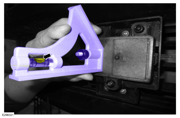
- Locate the CCM alignment screw.

|
|


- NOTE: Typical application shown.
NOTE: Measurement must be taken from the non-raised side of the CCM (cruise control module).
Place a combination square level on the face of the CCM and check the alignment.
|
|
- NOTE: Typical application shown.
NOTE: Measurement must be taken from the non-raised side of the CCM (cruise control module).
Keeping the combination square level on the face of the CCM , adjust the screw until the CCM is vertical and level.

|
|
- NOTE: Prior to installing the front bumper cover, clean and remove any debris on the front or back of the cover.
Install the front bumper cover.
Refer to: Front Bumper Cover (501-19 Bumpers, Removal and Installation).
Refer to: Front Bumper Cover - Vehicles With: SVT Performance Package (501-19 Bumpers, Removal and Installation).
Refer to: Front Bumper Cover - Vehicles With: SVT Performance Package (501-19 Bumpers, Disassembly and Assembly).
NOTE: The horizontal alignment for the CCM (cruise control module) is a software calibration check that is performed by the scan tool to insure the CCM (cruise control module) radar is pointed straight. No manual adjustment is needed for this procedure. The scan tool calibrates the CCM (cruise control module) through the CCM (cruise control module) procedure in programmable parameters. The Alignment Offset specification is +/- 3.0 degrees of offset.
- NOTICE: The vehicle's engine must be running during the horizontal alignment procedure. Failure to leave the engine running throughout the entire procedure results in the cancellation of the alignment procedure and the system remains non-functional.
Start the engine.
- Follow the scan tool on-screen instructions to carry-out the CCM calibration procedure.
OP
OP
Nodster
Well-Known Member
- Thread starter
- #20
Well she is finished. Doesn't start yet, but here is the last of the install work I did today.
So I noted that with the airbox installed for the JLT kit that the coolant hose was pushed against the side of the engine. I had some spare DEI thermal tape left from something I did ages ago, so I wrapped the pipe.


Then I made the adjustments to the intake to account for the slight blip in angle which fouled the hood from closing. New 30º pipe added.
Pleased with how it has turned out. Now, if I can only get the blasted thing to start!
Thanks.
So I noted that with the airbox installed for the JLT kit that the coolant hose was pushed against the side of the engine. I had some spare DEI thermal tape left from something I did ages ago, so I wrapped the pipe.


Then I made the adjustments to the intake to account for the slight blip in angle which fouled the hood from closing. New 30º pipe added.


Pleased with how it has turned out. Now, if I can only get the blasted thing to start!
Thanks.
Sponsored
OP
OP
Nodster
Well-Known Member
- Thread starter
- #22
Thanks - couldn't have done it with out you and the rest of the team! I forgot to post in here that the race valve is fitted. So that is the last of the supercharger work done. yey!looks great


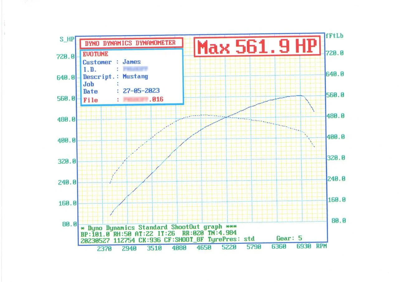
I'm also hitting the dyno next weekend, so it'll be nice to get some power figures as I have no idea what I'm making at the minute. Will post the figures up next weekend.
 Just re-sharing the little video of the car running (this was with the old bypass valve fitted).
raptor17GT
Well-Known Member

what boost figure is that? Loving the torque curve and the engine revving out til 6.9k revs
Sponsored
OP
OP
Nodster
Well-Known Member
- Thread starter
- #26
Good question I'm not actually sure, @Wengerd Performance i think was going to tell me but I never heard. Think he said he would calculate it for me. Any ideas?what boost figure is that? Loving the torque curve and the engine revving out til 6.9k revs

raptor17GT
Well-Known Member
surprised dyno operator wasn't measuring it. I wouldn't like to guess but your power figures (at wheels i presume) is about 190hp more than my own MY17 so that has to feel pretty good without the traction worries overwhelming the driving experience.Good question I'm not actually sure, @Wengerd Performance i think was going to tell me but I never heard. Think he said he would calculate it for me. Any ideas?
Last edited:
Wengerd Performance
Well-Known Member
- Joined
- Feb 27, 2021
- Threads
- 1
- Messages
- 244
- Reaction score
- 861
- Location
- Paris, Tn
- Website
- wengerdperformance.com
- First Name
- Derel
- Vehicle(s)
- 18 GT Whipple 15 Mustang GT TT 18 F150 VMP ODIN
I need to pull up one of your logs againGood question I'm not actually sure, @Wengerd Performance i think was going to tell me but I never heard. Think he said he would calculate it for me. Any ideas?
Wengerd Performance
Well-Known Member
- Joined
- Feb 27, 2021
- Threads
- 1
- Messages
- 244
- Reaction score
- 861
- Location
- Paris, Tn
- Website
- wengerdperformance.com
- First Name
- Derel
- Vehicle(s)
- 18 GT Whipple 15 Mustang GT TT 18 F150 VMP ODIN
7.5-8psi range
Sponsored