Sponsored

Fore fuel regulator mounting

gqneon

Well-Known Member
Joined
Jun 25, 2015
Threads
91
Messages
867
Reaction score
144
Location
Westfield, IN
Vehicle(s)
18 GT PP / Manual
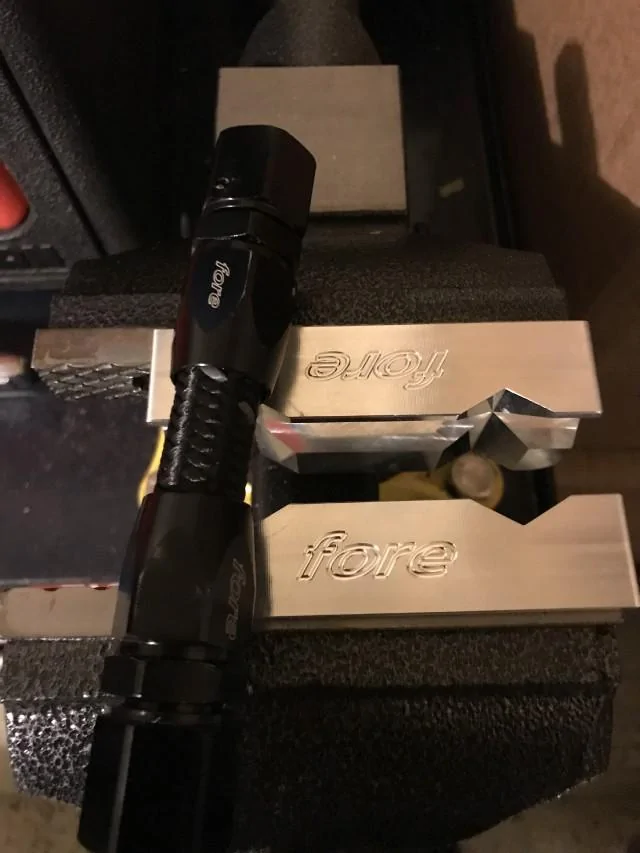
I’m looking under the hood of my 15GT vert and trying to figure where he heck I’m going to mount this fore fuel pressure regulator. I’m thinking since the front of the driver shock tower is consumed by the closed Whipple air box and filler neck assembly, my next best bet is mounting it horizontally on the side of the driver shock tower but I’ll have to relocate the mechanical pressure gauge.

Where are you guys mounting your regulators for aftermarket fuel systems on the S550 ? Pics would be awesome to show me where you chose to put yours and maybe a line or two about the pluses and minuses you experienced with it where it is.

Looking forward to seeing what works best! :cheers:
Sponsored


db252

Equinsu Ocha
Joined
Jan 1, 2016
Threads
44
Messages
1,473
Reaction score
890
Location
Bay Area, CA
Vehicle(s)
16 GT Premium/PP/Nav
This is how I mounted mine. There is some material you have to grind/cut off on the shock tower to make it sit flattish. I drilled two holes inline with the mounting bracket and put two bolts through and nylock nuts to secure it. Once securing it, the bracket forms nicely to the shock tower.

 
OP
OP
gqneon

gqneon

Well-Known Member
Joined
Jun 25, 2015
Threads
91
Messages
867
Reaction score
144
Location
Westfield, IN
Vehicle(s)
18 GT PP / Manual
Near center on the firewall
Thanks - any chance you could post a picture or two for me to see? I looked there and thought that area could work also!
 
OP
OP
gqneon

gqneon

Well-Known Member
Joined
Jun 25, 2015
Threads
91
Messages
867
Reaction score
144
Location
Westfield, IN
Vehicle(s)
18 GT PP / Manual
This is how I mounted mine. There is some material you have to grind/cut off on the shock tower to make it sit flattish. I drilled two holes inline with the mounting bracket and put two bolts through and nylock nuts to secure it. Once securing it, the bracket forms nicely to the shock tower.

This is exactly what I’m looking for. I thought this location would be an area easier to service or move out of the way for other work or maintenance. This photo answers a lot of questions. It looks like I can mount it higher up than I was thinking as far as hood clearance goes - I have a stock hood - is yours stock also? It looks like you paralleled Your rails - the outlet is on the front on the driver side , is the outlet or inlet on the front of the passenger rail? I can’t see the feed line to the rails but I’m guessing it’s y-blocked and feeds the back of both rails?

Any chance I can bribe you to take a picture of the feed setup and both rails?

I was going to do my rails in series but the way you have it set up might be the way to go. Thanks for the response man! The picture is exactly the way my car is set up too (catch can, CC plates, etc) - its like looking under my own hood, color included.

I like that you can see the mechanical gauge where it’s mounted too - I need to lay it out and mock everything up before I decide.
 

Sponsored

db252

Equinsu Ocha
Joined
Jan 1, 2016
Threads
44
Messages
1,473
Reaction score
890
Location
Bay Area, CA
Vehicle(s)
16 GT Premium/PP/Nav
This is exactly what I’m looking for. I thought this location would be an area easier to service or move out of the way for other work or maintenance. This photo answers a lot of questions. It looks like I can mount it higher up than I was thinking as far as hood clearance goes - I have a stock hood - is yours stock also? It looks like you paralleled Your rails - the outlet is on the front on the driver side , is the outlet or inlet on the front of the passenger rail? I can’t see the feed line to the rails but I’m guessing it’s y-blocked and feeds the back of both rails?

Any chance I can bribe you to take a picture of the feed setup and both rails?

I was going to do my rails in series but the way you have it set up might be the way to go. Thanks for the response man! The picture is exactly the way my car is set up too (catch can, CC plates, etc) - its like looking under my own hood, color included.

I like that you can see the mechanical gauge where it’s mounted too - I need to lay it out and mock everything up before I decide.
Perfect location as far as I’m concerned. It’s in the way of nothing, has tons of clearance, the dipstick comes out easily and I am running a stock hood. My system is a Fore level 4. My feed lines come into both rails at the firewall after my Y block and my returns come from both fronts to the regulator and you are correct in thinking my system is in parallel. This pic should give you a clear view and you can also see the vacuum line.

 
OP
OP
gqneon

gqneon

Well-Known Member
Joined
Jun 25, 2015
Threads
91
Messages
867
Reaction score
144
Location
Westfield, IN
Vehicle(s)
18 GT PP / Manual
That’s great man - it’s a huge help. It looks like you ran ptfe line for your boost reference line too? Hardcore lol... I got some pushlock line and the vacuum block from fore and was going to go that route on may car. I can’t see where you tapped in though for boost reference is that on the driver or passenger side of the Whipple manifold?

Tons of questions but I reall like the way you did yours!
 

db252

Equinsu Ocha
Joined
Jan 1, 2016
Threads
44
Messages
1,473
Reaction score
890
Location
Bay Area, CA
Vehicle(s)
16 GT Premium/PP/Nav
Lol, not PTFE line for my vacuum line. Just stainless sheathed rubber vacuum line with -an fittings to match the setup and satisfy my OCD. The boost reference comes from a port that is plugged on the drivers back side.

Thanks for the words. Don’t hesitate to ask any other questions.


OP
OP
gqneon

gqneon

Well-Known Member
Joined
Jun 25, 2015
Threads
91
Messages
867
Reaction score
144
Location
Westfield, IN
Vehicle(s)
18 GT PP / Manual
That’s friggin boss man. I’m assuming the fittings on the front of both rails are those 90 + 90 fittings from fore since they turn the exit hoses 180* back towards the firewall where you routed them to either pressure port on the regulator sides. Did you use straight or 90* fittings on the back of the rails for the fuel entry from the lines off the y-block? I think the rest of this install is mapped out in my head. The pictures are [I]extremely[/I] helpful so far!

Any issues with mounting the fuel filter or check valve or anything from the tank side forward? Any pro tips ? I’m a little ocd on installs myself!
 

db252

Equinsu Ocha
Joined
Jan 1, 2016
Threads
44
Messages
1,473
Reaction score
890
Location
Bay Area, CA
Vehicle(s)
16 GT Premium/PP/Nav
Thanks again.

Here are the fittings that were supplied and used. The 180’s for the front of the rails and the 90’s for the back. TIP: attatchnthe back lines with fittings while the rails are not secured to the manifold. Gives you better access for tightening before you set the rails.


There are lots of ‘right’ ways to install the system and definitely wrong ways. Here’s a few more pics of the way I did it. No issues.


Sponsored
OP
OP
gqneon

gqneon

Well-Known Member
Joined
Jun 25, 2015
Threads
91
Messages
867
Reaction score
144
Location
Westfield, IN
Vehicle(s)
18 GT PP / Manual
Man - this is greatness. So if I'm following your routing correctly, after the y block you ran 1 feed line through some foam insulation under that bracket, and the other two lines zip tied to the brake line position are a feed and a return? And the return is fed through the opening in the stock brake line / single fuel line holders? I didn't even know there was an open space - but I guess that is perfect for this.

In the install pictures the stock fuel line is left in place - did you leave them in after you were done for simplicity reinstalling the stock fuel system later down the road? It makes sense if so - and if the components aren't in the way.

Something I don't see and didn't think to ask - where in your plumbing setup is your check valve?
 

db252

Equinsu Ocha
Joined
Jan 1, 2016
Threads
44
Messages
1,473
Reaction score
890
Location
Bay Area, CA
Vehicle(s)
16 GT Premium/PP/Nav
Correct on all the routing. There are also some sound/vibration dampening pads where the lines without the foam are going through the bracketjust for my own piece of mind.

The return is where the stock lines go and you’ll be able to put the stock cover back on after you run the line. I’m sure I did more securing before it was completed. You’ll do a little trimming on that cover but that will be self explanatory.

Thought about taking out the stock system but I figured why?? There is no need to remove it. I unlatched the stock feed in the engine compartment and put a plug over the line. The stock connection that went to the factory fuel pump is just taped off. Nothing is in the way.

The check valve is directly attached to the fuel filter on the pump(s) side. Keeping the check valve close to the pumps ensures almost the entire fuel system stays primed.
 
OP
OP
gqneon

gqneon

Well-Known Member
Joined
Jun 25, 2015
Threads
91
Messages
867
Reaction score
144
Location
Westfield, IN
Vehicle(s)
18 GT PP / Manual
Great info man. Thanks a ton. Now that the wife is away I'm going to go open the box and lay everything out in the garage and make a decision on going series vs parallel fitting / routing wise. I am not sure if going parallel or series has any advantage at my power level or not - or which is easier to set up really - but I'd prefer to do it all once vs twice like anything else so I'm leaning towards ordering some additional bits and pieces to go parallel since that seems to be the end-all system.

Any additional thoughts or tips you think of down the road, feel free to drop in here for me. Rick at Fore recommended using vaseline on the threads of the fittings and the spindles into the hose (I went with Flex LP to prevent the vibration issues vs PTFE) - I have some thread sealant but think that's probably only going on the gauge or any sensor fittings - the AN fittings look like sealant wouldn't have any purpose if I'm thinking all this through correctly.
 

kcc0521

Well-Known Member
Joined
Feb 24, 2015
Threads
231
Messages
2,169
Reaction score
307
Location
Falls Church VA
First Name
Bo
Vehicle(s)
2015 Black GT PP
Correct on all the routing. There are also some sound/vibration dampening pads where the lines without the foam are going through the bracketjust for my own piece of mind.

The return is where the stock lines go and you’ll be able to put the stock cover back on after you run the line. I’m sure I did more securing before it was completed. You’ll do a little trimming on that cover but that will be self explanatory.

Thought about taking out the stock system but I figured why?? There is no need to remove it. I unlatched the stock feed in the engine compartment and put a plug over the line. The stock connection that went to the factory fuel pump is just taped off. Nothing is in the way.

The check valve is directly attached to the fuel filter on the pump(s) side. Keeping the check valve close to the pumps ensures almost the entire fuel system stays primed.

What type of tool did you use to disconnect the factory feed line at the fire wall. Is it a springtype connection like older fuel injected lines and ac lines?
 
OP
OP
gqneon

gqneon

Well-Known Member
Joined
Jun 25, 2015
Threads
91
Messages
867
Reaction score
144
Location
Westfield, IN
Vehicle(s)
18 GT PP / Manual
B54_F1_CCF_4_E96_43_D6_87_AF_6_F5774_B97882.webp


Step one - test fitting my first hose connection check valve to filter to get a feel for those assembly part. It’s about as simple as simple gets. Love it.

OCD has already kicked in though, I misaligned the logos on the fittings... might cut a new section and do it again lol
Sponsored


Top