
Sponsored
OP
OP
Skye
Well-Known Member
- Thread starter
- #17
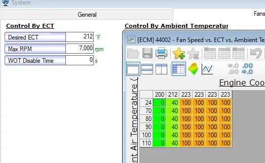
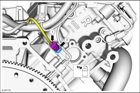
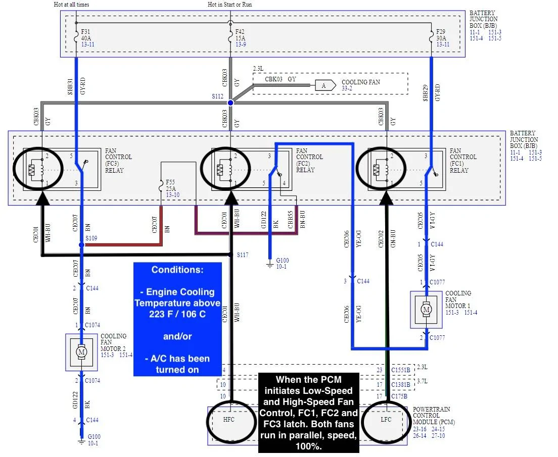
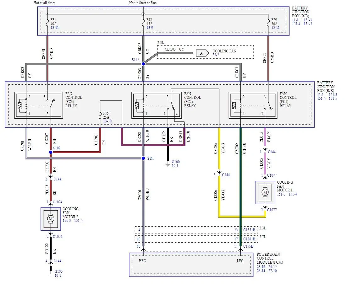
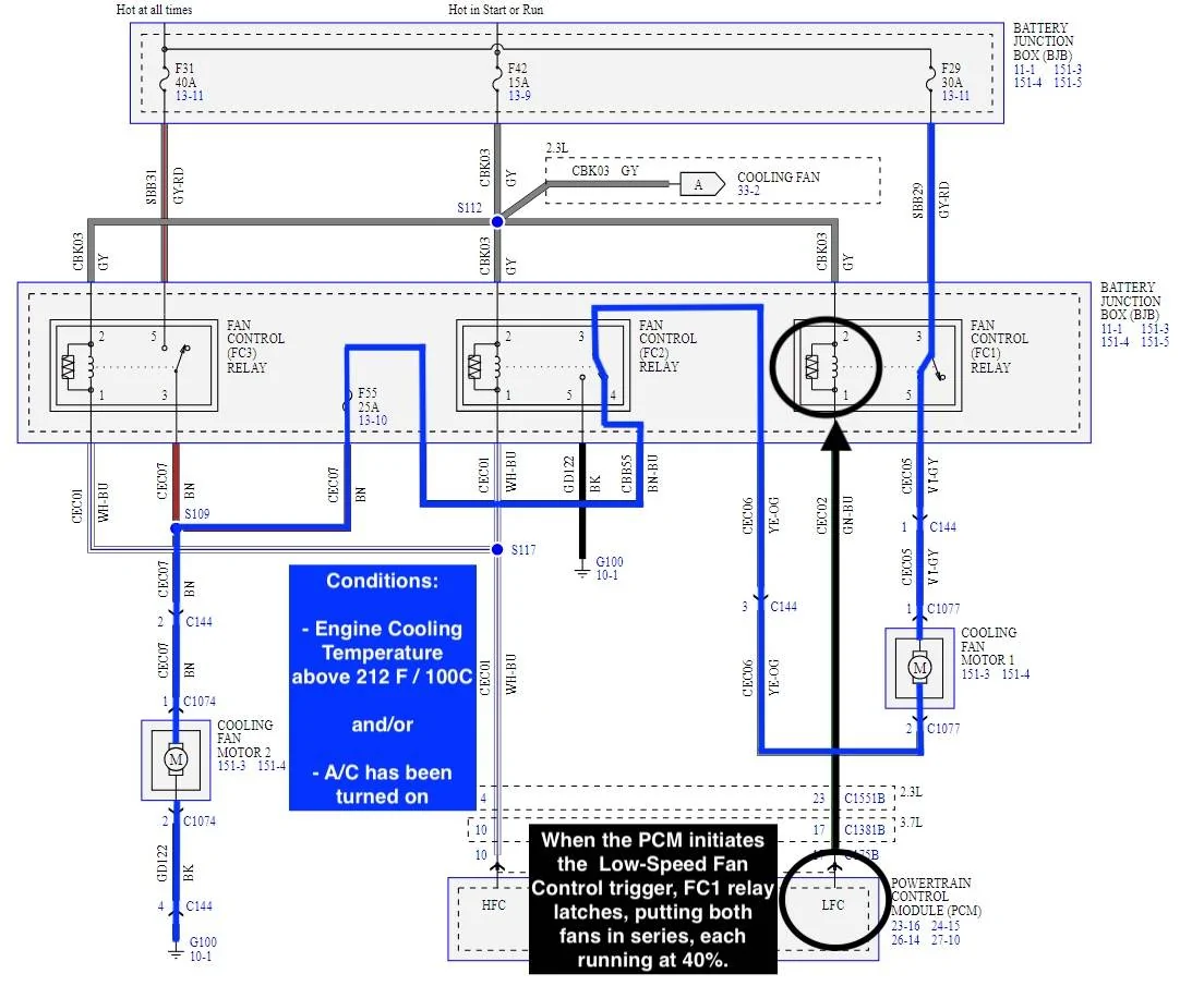
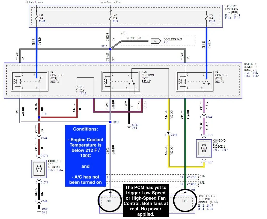
Attached is a table, picture and some schematics related to Coyote engine cooling and fans.
The Coyote has a Cylinder Head Temperature (CHT) sensor; this sensor rests in the back of the head, passenger side. The sensor itself is a thermistor. The resistance of the sensor changes with temperature, with any reference voltages then adjusting as a result. The CHT is what we see when viewing the in-dash display.
Some manufacturers will produce engines with Engine Coolant Temperature (ECT) sensors. These sensors rest in a coolant jacket and read liquid temperatures directly. The Coyote does not have an ECT sensor. In the Powertrain Control Module, software derives the ECT from the CHT. Fans are then turned on/off based on the ECT and other logic.
One can think of ECT as a raw reading at one point in time, while CHT is a measure of everything. ECT + engine load = CHT. ECT can be read with scanner/tuning tools and software. Under light loads, ECT/CHT could be pretty close to one another, while during more spirited driving, ECT/CHT could differ by as much as 10+ degrees, the ECT always being cooler.
When the fans are needed, they will both come on. There is a low-power mode and a high-power mode. The attached schematics will provide insight and might assist in t-shooting an issue.
Why two fans? Fans are to a radiator as pixels are to a photo. The smaller the fan, the greater the coverage (higher resolution).
Why run both at the same time? More uniform cooling across the face of the radiator.


The Coyote has a Cylinder Head Temperature (CHT) sensor; this sensor rests in the back of the head, passenger side. The sensor itself is a thermistor. The resistance of the sensor changes with temperature, with any reference voltages then adjusting as a result. The CHT is what we see when viewing the in-dash display.
Some manufacturers will produce engines with Engine Coolant Temperature (ECT) sensors. These sensors rest in a coolant jacket and read liquid temperatures directly. The Coyote does not have an ECT sensor. In the Powertrain Control Module, software derives the ECT from the CHT. Fans are then turned on/off based on the ECT and other logic.
One can think of ECT as a raw reading at one point in time, while CHT is a measure of everything. ECT + engine load = CHT. ECT can be read with scanner/tuning tools and software. Under light loads, ECT/CHT could be pretty close to one another, while during more spirited driving, ECT/CHT could differ by as much as 10+ degrees, the ECT always being cooler.
When the fans are needed, they will both come on. There is a low-power mode and a high-power mode. The attached schematics will provide insight and might assist in t-shooting an issue.
Why two fans? Fans are to a radiator as pixels are to a photo. The smaller the fan, the greater the coverage (higher resolution).
Why run both at the same time? More uniform cooling across the face of the radiator.
Last edited:
OP
OP
Skye
Well-Known Member
- Thread starter
- #20
Using Ford technical manual diagrams, this video identifies the location of several modules throughout the car. Best viewed in full screen mode. While watching the video, the item of interest is listed in the left side panel.
Each of the posted primer documents have had their appendices updated with this link. If you've previously downloaded one of those files, one can go back and pull it again.
Each of the posted primer documents have had their appendices updated with this link. If you've previously downloaded one of those files, one can go back and pull it again.
Last edited:
Sponsored
OP
OP
Skye
Well-Known Member
- Thread starter
- #22
Attached is an updated primer on charging systems. While the initial document was OK, it didn't have a section on Absorbed Glass Mat (AGM) batteries, a type some 6G owners have gravitated to. I've also added some new link references, cleaned up formatting, etc.
One of the links in the primer connects to a second attachment here: a reference from the Battery Council International (BCI), laying out batteries by group, size and Cold Cranking Amperage (CCA).
One of the links in the primer connects to a second attachment here: a reference from the Battery Council International (BCI), laying out batteries by group, size and Cold Cranking Amperage (CCA).
Attachments
-
1.3 MB Views: 135
-
5.7 MB Views: 50
Last edited:
OP
OP
Skye
Well-Known Member
- Thread starter
- #23
In another forum for Toyotas, I recently commented on fobs and how to keep them from interacting with other devices. It was in response to the topic of the thread: fobs with batteries being drained much sooner than expected.
As a follow-up to my initial post in that forum, I studied Near Field Communications (NFC). Many use the NFC function on their cell phones for contactless payment, authentication or communication.
Detailed thoughts below, but if you are using NFC on your phone, keep it away from any fob. Keep the fob in a Faraday pouch when not in use.
For the unfamiliar, a quick brief on fobs and Intelligent Access in the 6G...
At rest, our Mustang's door handles generate an induction field. When a fob is brought into the field, the door handle then sends out a 125 KiloHertz (KHz), Radio Frequency IDentification (RFID) wake signal. This signal tells the fob to use the fob's Ultra-High Frequency (UHF) transmitter to authenticate to the car. The UHF receiver is in the parcel shelf in the back of the car.
When we touch the inside of the handle, if authenticated, a capacitive-sensitive contact patch will recognize the hand and unlock the car.
The UHF frequency is the same as used for the Tire Pressure Monitoring System: 315 MegaHertz (MHz) in the US and 433 MHz in EUR.
Back to the thread in the Toyota forum...
Someone posted how their relative had issues with a fob whose battery had died much sooner than expected. They stated a cell phone was to blame. In researching the cause and a fix, a Toyota dealer mentioned keeping cell phones away from the fob. That seemed to have fixed the issue.
^ That interested me. I never considered how a cell phone could impact a fob. The fob operating frequencies are no where near 5G, bluetooth or wireless (802.11) services. Then I started thinking about NFC. In the "Edit" section below are my thoughts on how NFC could negatively impact a fob.
-----------------------------------------------------------------------
Hopefully, some of these issues have just been poor batteries from the factory.
Once replaced, there are some things that can help extend its life:
- When the fob is at rest, look for the small light on the body of the fob. If that light is blinking red, the fob is communicating with something. And draining its battery
- When not in use, the fob should be kept as far from the truck as possible. In the door handle of the truck, there's an inductive coil generating a field. If the fob enters that field, the truck and the fob then begin authenticating and communicating via radio signals. Checking mine just now, my fob went active about 6 ft / 2 m from the truck. I haven't walked all around to measure the max distance. Other makes, I've noticed fobs can go active further out
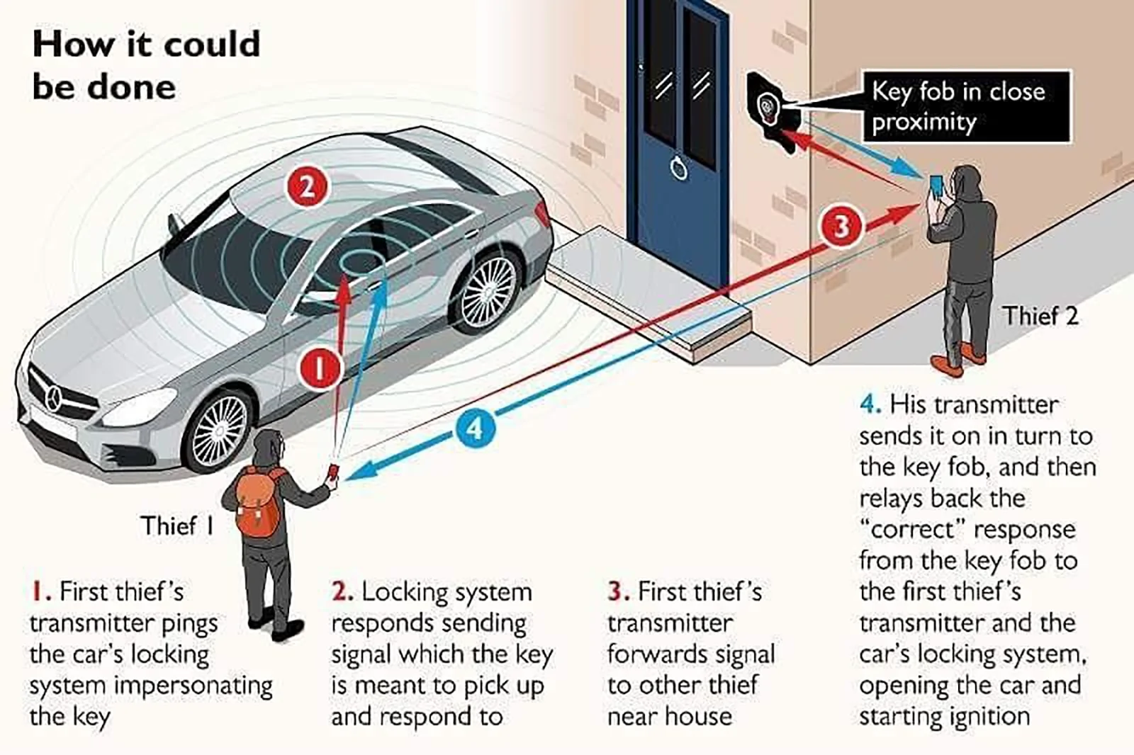
- If stimulated with an Radio Frequency IDentification (RFID) signal (often 125 KiloHertz (KHz)), the fob will transmit a Ultra-High Frequency (UHF) signal in an effort to authenticate to the truck. When not needed, keep the fob in a faraday pouch; this will prevent the fob from pairing with anything. It also keeps the truck that much more secure. In the example of a relay attack, two people could take the truck in moments
Edit,
Wireless charging systems are more common and greater in use. If you have a device with a coil and are charging it, great. If it's something like a fob or other electronic device, keep those well away from charging pads and wireless charging systems.
Edit (again),
I'm still studying the specifications, but I was interested in the cell phone comments, how a cell phone could drain a fob.
Cell phones operate in the GigaHertz (GHz) range. Bluetooth is also GHz. But what about Near Field Communications (NFC)? NFC operates in the MegaHertz (MHz) range, 13.56 MHz. NFC also allows for induction fields and power transfer involving those.
While RFID for vehicle fobs is often at 125 KHz , the RFID specification does have a high frequency: 13.56 MHz. The fob is an RFID receiver. If built to receive 13.56 MHz, that would set the fob off. It'd use its UHF transmitter to authenticate to the truck.
This ^ interests me...so someone is buzzing out in front of the TV, the cell phone with NFC on, the fob near that, lit and talking to the truck. Is that an opportunity for someone to walk up to the truck and open it?
In another scenario, using NFC, a cell phone and its internal coil can power a powerless device, to communicate with it. The attempted power transfer could set something off in the fob.
Not something I want to trial though. As mentioned above, placing general electronic devices next to those which can transfer power can lead to damage in the non-NFC, non-induction device.
https://nfc-forum.org/learn/nfc-technology/
https://iotjourney.orange.com/en/support/faq/what-is-the-difference-between-nfc-and-rfid

As a follow-up to my initial post in that forum, I studied Near Field Communications (NFC). Many use the NFC function on their cell phones for contactless payment, authentication or communication.
Detailed thoughts below, but if you are using NFC on your phone, keep it away from any fob. Keep the fob in a Faraday pouch when not in use.
For the unfamiliar, a quick brief on fobs and Intelligent Access in the 6G...
At rest, our Mustang's door handles generate an induction field. When a fob is brought into the field, the door handle then sends out a 125 KiloHertz (KHz), Radio Frequency IDentification (RFID) wake signal. This signal tells the fob to use the fob's Ultra-High Frequency (UHF) transmitter to authenticate to the car. The UHF receiver is in the parcel shelf in the back of the car.
When we touch the inside of the handle, if authenticated, a capacitive-sensitive contact patch will recognize the hand and unlock the car.
The UHF frequency is the same as used for the Tire Pressure Monitoring System: 315 MegaHertz (MHz) in the US and 433 MHz in EUR.
Back to the thread in the Toyota forum...
Someone posted how their relative had issues with a fob whose battery had died much sooner than expected. They stated a cell phone was to blame. In researching the cause and a fix, a Toyota dealer mentioned keeping cell phones away from the fob. That seemed to have fixed the issue.
^ That interested me. I never considered how a cell phone could impact a fob. The fob operating frequencies are no where near 5G, bluetooth or wireless (802.11) services. Then I started thinking about NFC. In the "Edit" section below are my thoughts on how NFC could negatively impact a fob.
-----------------------------------------------------------------------
Hopefully, some of these issues have just been poor batteries from the factory.
Once replaced, there are some things that can help extend its life:
- When the fob is at rest, look for the small light on the body of the fob. If that light is blinking red, the fob is communicating with something. And draining its battery
- When not in use, the fob should be kept as far from the truck as possible. In the door handle of the truck, there's an inductive coil generating a field. If the fob enters that field, the truck and the fob then begin authenticating and communicating via radio signals. Checking mine just now, my fob went active about 6 ft / 2 m from the truck. I haven't walked all around to measure the max distance. Other makes, I've noticed fobs can go active further out
- If stimulated with an Radio Frequency IDentification (RFID) signal (often 125 KiloHertz (KHz)), the fob will transmit a Ultra-High Frequency (UHF) signal in an effort to authenticate to the truck. When not needed, keep the fob in a faraday pouch; this will prevent the fob from pairing with anything. It also keeps the truck that much more secure. In the example of a relay attack, two people could take the truck in moments
Edit,
Wireless charging systems are more common and greater in use. If you have a device with a coil and are charging it, great. If it's something like a fob or other electronic device, keep those well away from charging pads and wireless charging systems.
Edit (again),
I'm still studying the specifications, but I was interested in the cell phone comments, how a cell phone could drain a fob.
Cell phones operate in the GigaHertz (GHz) range. Bluetooth is also GHz. But what about Near Field Communications (NFC)? NFC operates in the MegaHertz (MHz) range, 13.56 MHz. NFC also allows for induction fields and power transfer involving those.
While RFID for vehicle fobs is often at 125 KHz , the RFID specification does have a high frequency: 13.56 MHz. The fob is an RFID receiver. If built to receive 13.56 MHz, that would set the fob off. It'd use its UHF transmitter to authenticate to the truck.
This ^ interests me...so someone is buzzing out in front of the TV, the cell phone with NFC on, the fob near that, lit and talking to the truck. Is that an opportunity for someone to walk up to the truck and open it?
In another scenario, using NFC, a cell phone and its internal coil can power a powerless device, to communicate with it. The attempted power transfer could set something off in the fob.
Not something I want to trial though. As mentioned above, placing general electronic devices next to those which can transfer power can lead to damage in the non-NFC, non-induction device.
https://nfc-forum.org/learn/nfc-technology/
https://iotjourney.orange.com/en/support/faq/what-is-the-difference-between-nfc-and-rfid
Sponsored
Attachments
-
1.3 MB Views: 10
-
334.7 KB Views: 13
Last edited:
Similar threads


- Replies
- 3
- Views
- 1,277
