Sponsored

diy thermocouple data logging

ihasnostang

Well-Known Member
Joined
Sep 28, 2018
Threads
25
Messages
472
Reaction score
237
Location
MN
Website
www.youtube.com
Vehicle(s)
Saturn ion, 2019 201A, EB PP1, Ruby Red
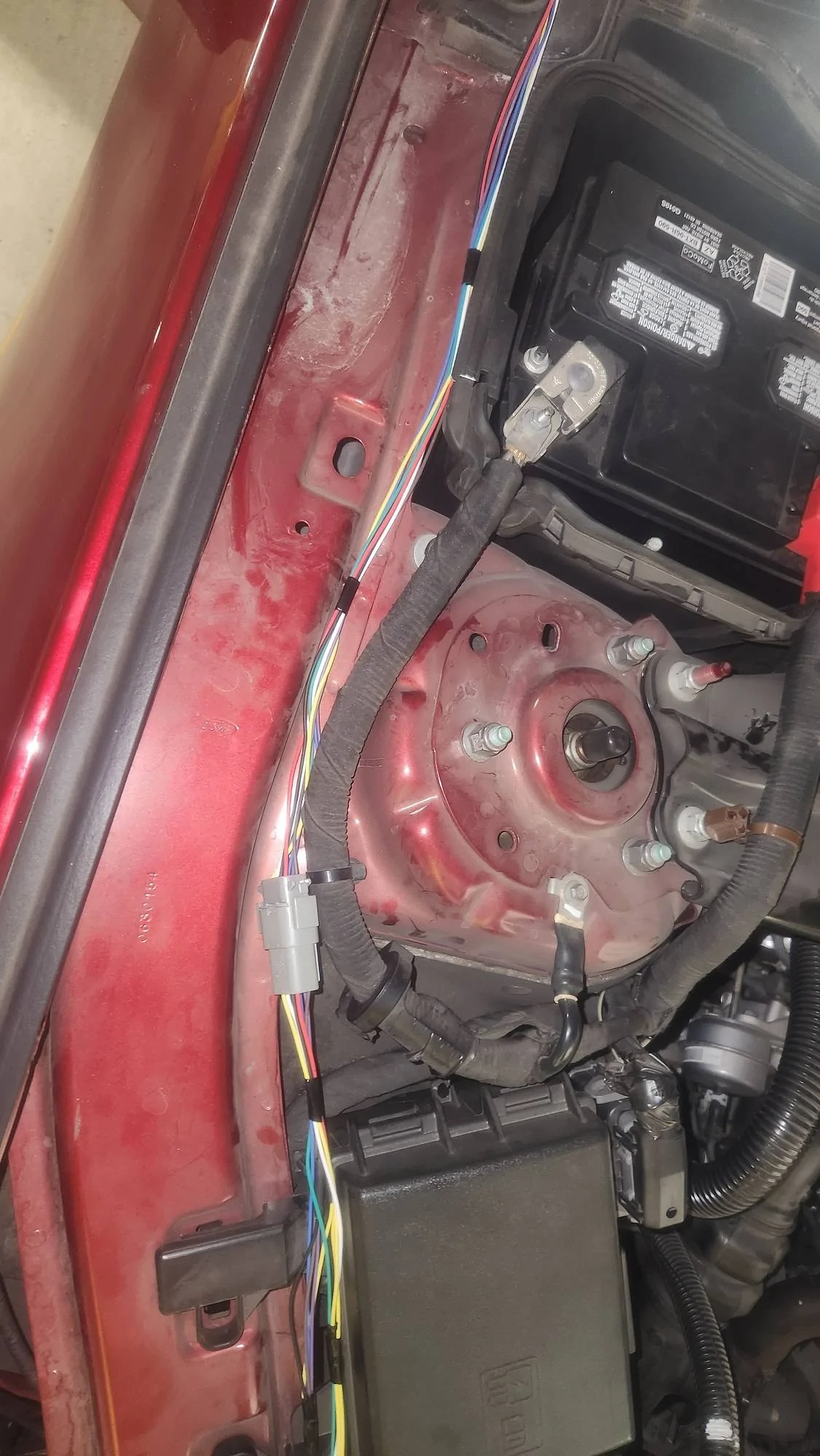
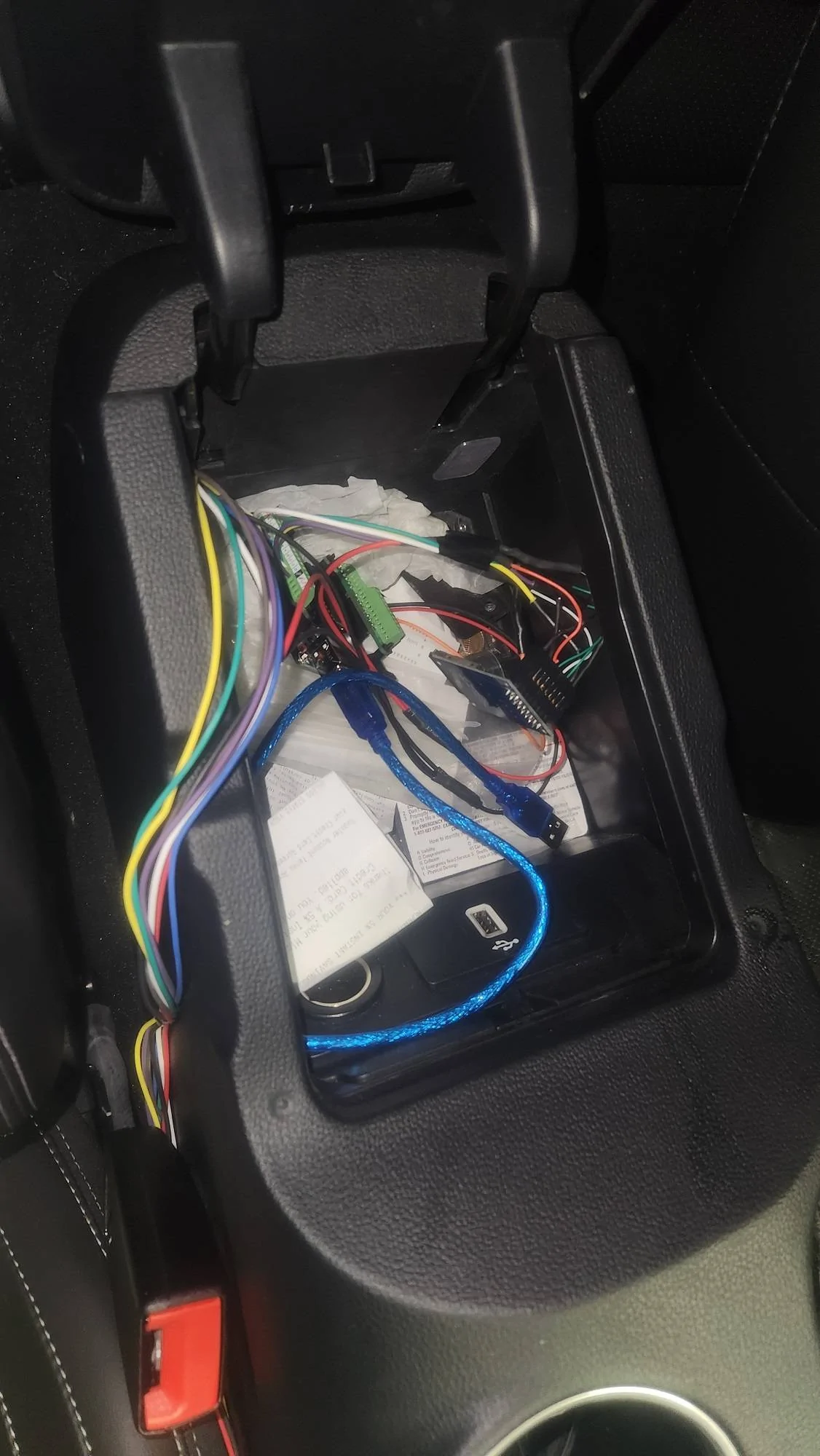
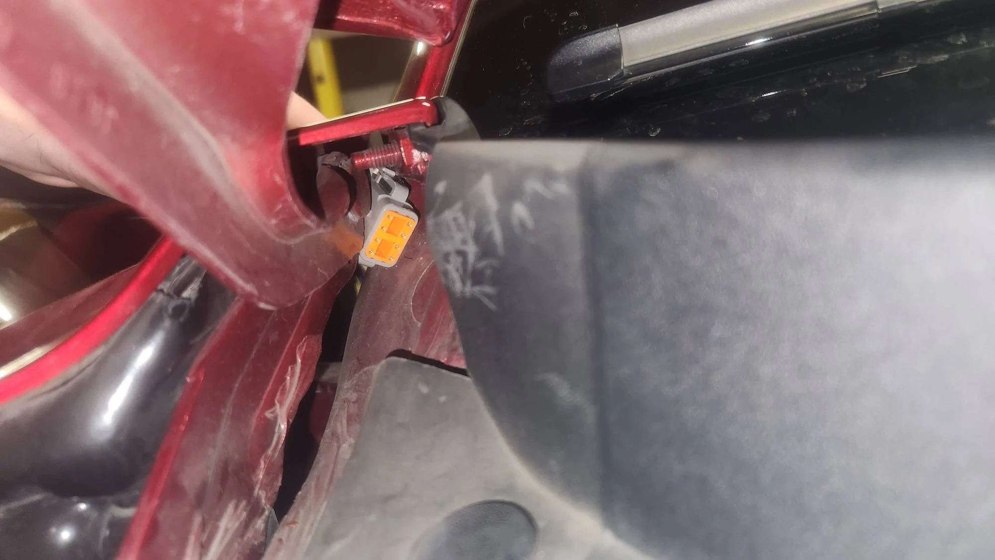
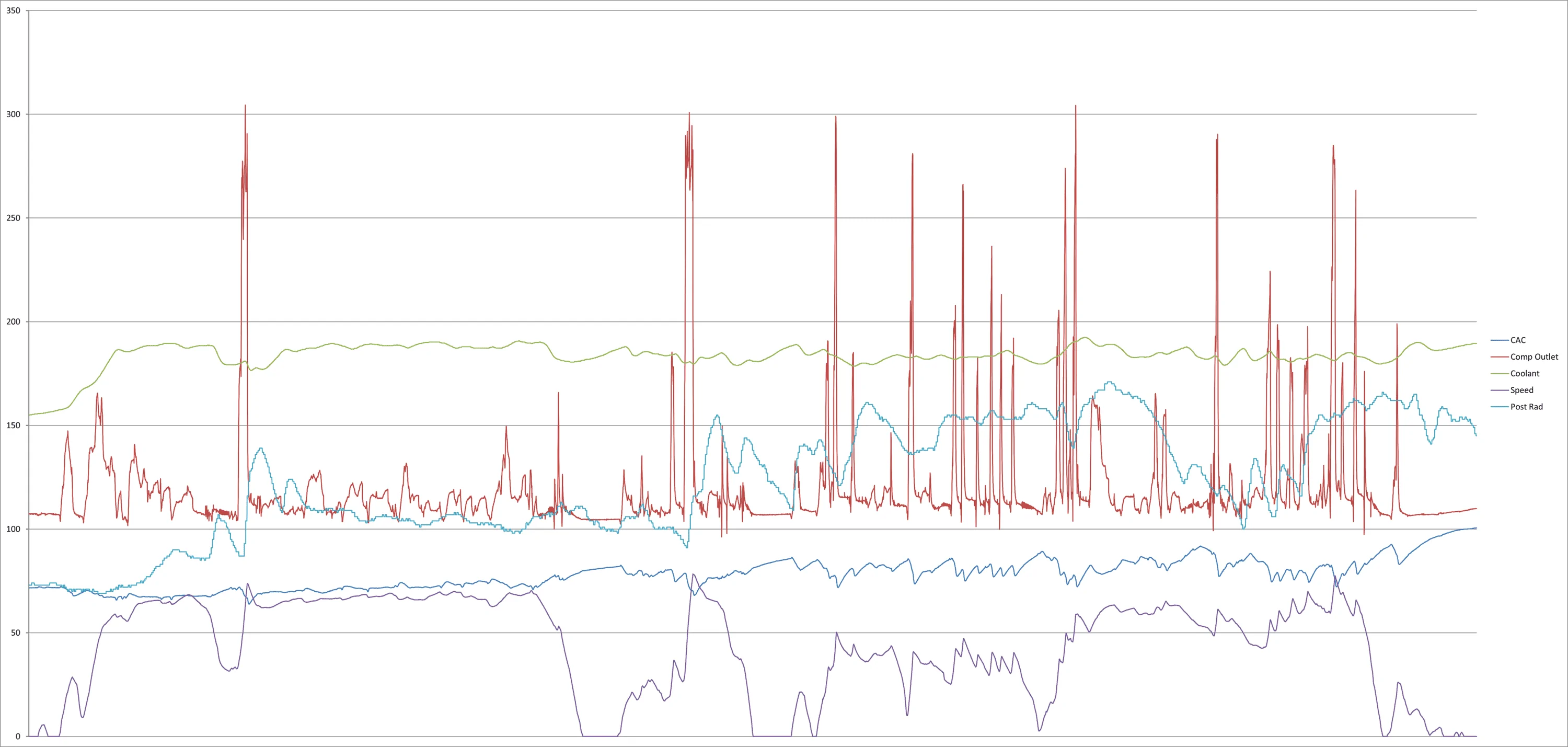
With this project i wanted to datalog air temperatures behind the intercooler as well as behind the radiator during track time, while being able to sync this data with datalog from the cobb accessport, which than can be overlayed onto track footage in RaceRender. I am by no means good at coding but i was able to write a code that reads two thermocouple temps every second and then writes to SD card. As soon as the arduino receives power the script automatically starts recording. The arduino and sd card module will be stored in the center console and routed behind the seat, along the door sill, through the door jam, and then along the fender. This setup is very low power and should have at least 24 hours of runtime from a 2000mAh battery pack. I have decided to add a set of 8 position DTM connectors under hood to split the harness into two parts. Wiring will start end of april

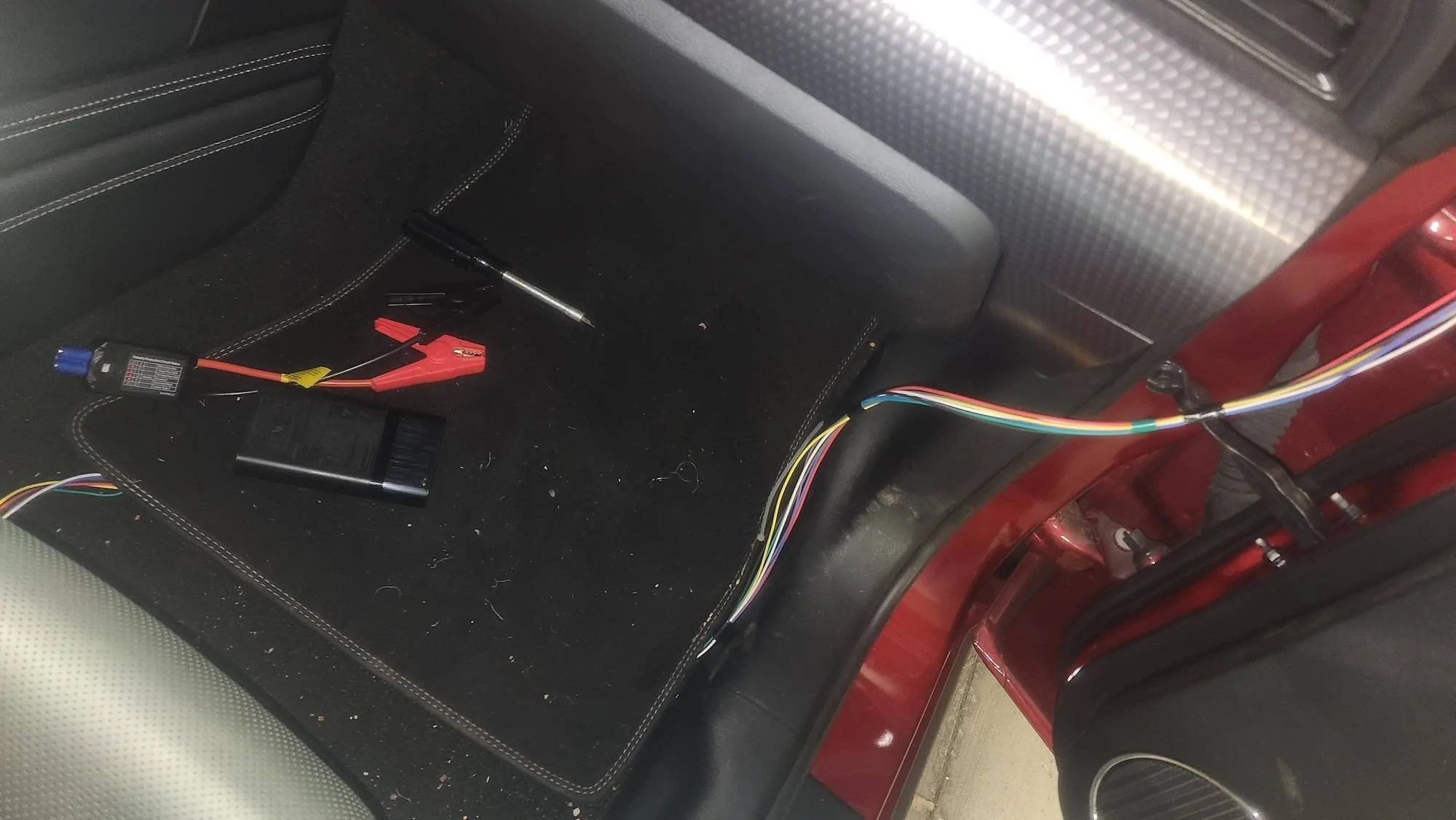
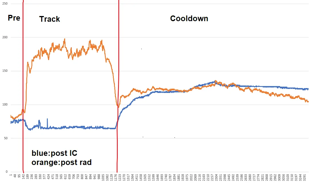
-Previous test using temperature function on a multi meter (pictures 1,2)
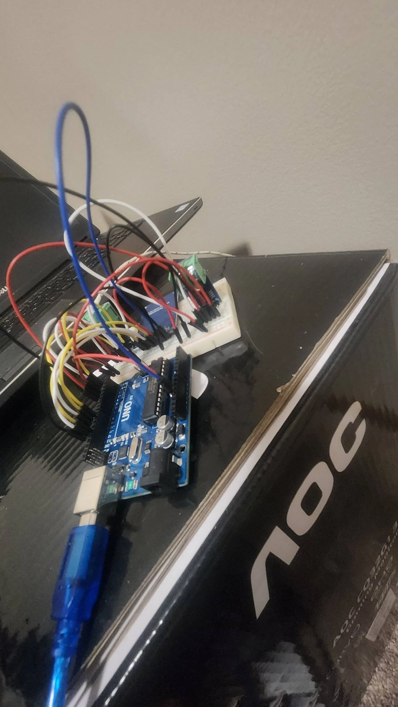
- testing code (picture 3)
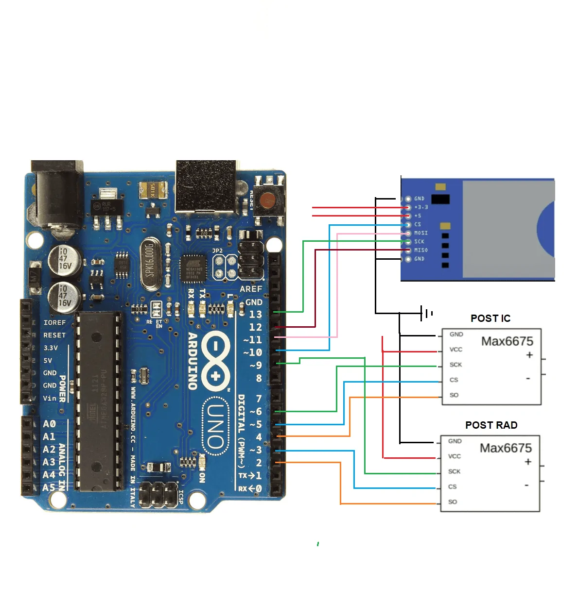
- wiring schematic (picture 4)
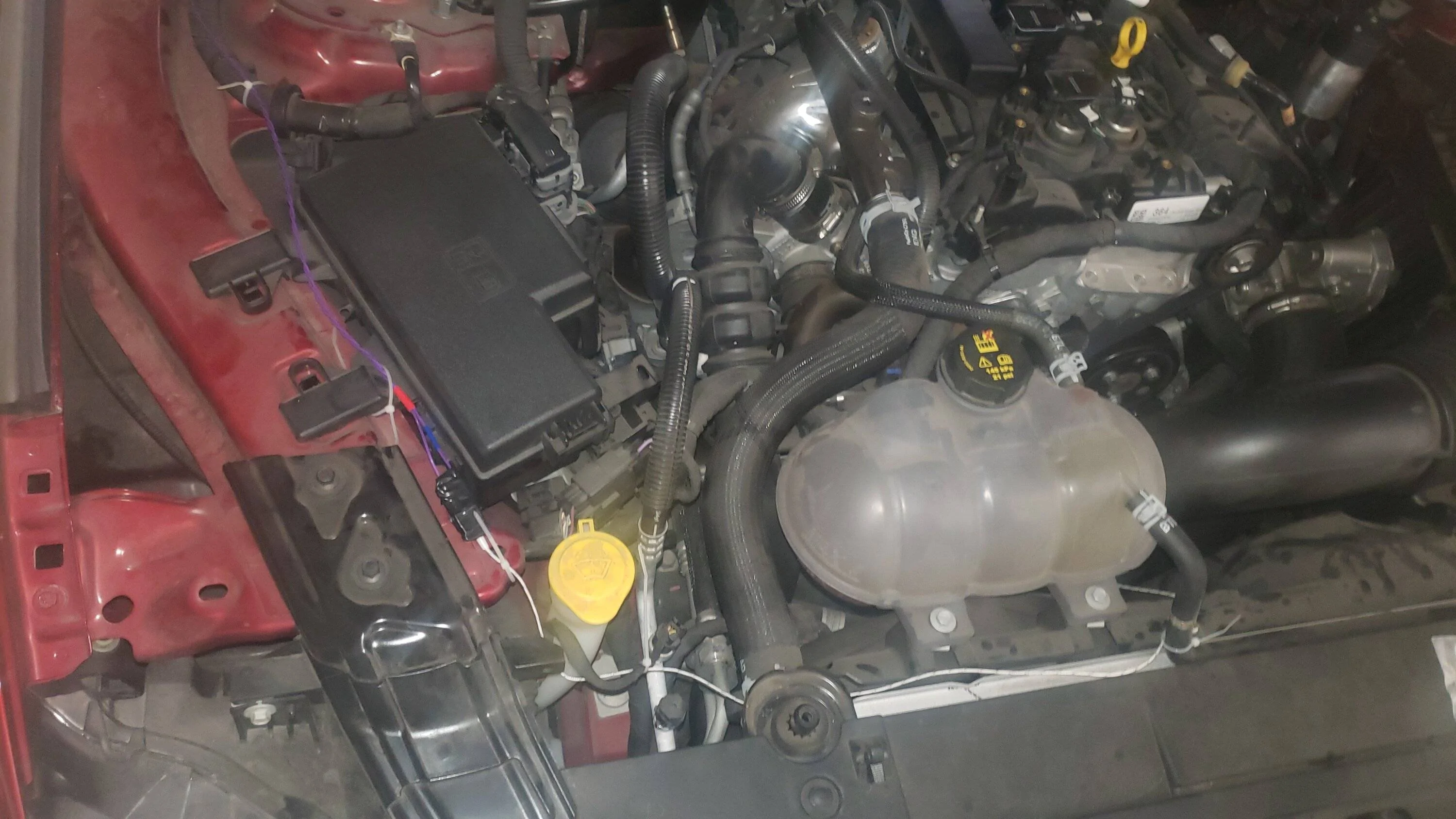
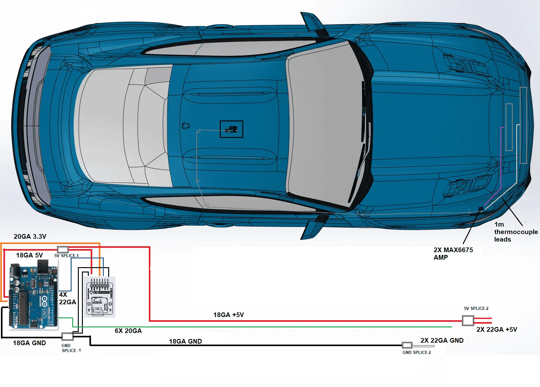
-wire routing (picture 5)
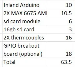
-BOM , wires not included but will be free from work(picture 6)


20220924_125608.jpg


20220924_125616.jpg


20230420_220324.jpg


arduino-uno-r3-development-board1.png


routing.png


bom.JPG
Sponsored

 
Last edited:
OP
OP

ihasnostang

Well-Known Member
Joined
Sep 28, 2018
Threads
25
Messages
472
Reaction score
237
Location
MN
Website
www.youtube.com
Vehicle(s)
Saturn ion, 2019 201A, EB PP1, Ruby Red
spent about 4 hours today putting together the harness. a lot splicing wires, many of which were very thin wires for the header connections. only issue i ran into was the DTM 8 position doesn't fit through the area below the hinge point of the hood. I will probably fix that by changing to two DTM 4 positions. the two separate leads going to the thermocouples will be zip tied to the connector going to the steel AC line

20230428_215357.jpg


20230428_215718.jpg


20230428_215704.jpg


20230428_215509.jpg


20230428_220411.jpg
 
Last edited:
OP
OP

ihasnostang

Well-Known Member
Joined
Sep 28, 2018
Threads
25
Messages
472
Reaction score
237
Location
MN
Website
www.youtube.com
Vehicle(s)
Saturn ion, 2019 201A, EB PP1, Ruby Red
first test today after adding some loom to the engine harness and swapping from 1 to 2 connectors. I tested it at my computer and it worked but by the time i got everything installed in the car the post intercooler temp wasn't reading, only the one behind the radiator was working. The accessport logs at 14hz and my arduino logs at 1hz, so i used excel to duplicate the 1 second of data 14 times. The only real indication of load is the compressor outlet temp. ampbient temp was 64 degrees.

Parameters logged:
Charge air temp
Compressor outlet temp (calculated)
Coolant temp
vehicle speed
Post rad temp


Results?
Interesting the post rad temp increase is slightly delayed from heavy throttle input

Next step: Aside from getting both sensors working; do a highway steady state test and have someone activate the HFC high fan speed circuit while driving to compare the effect. I will need to learn forscan data logging before hand.

20230505_191711.jpg


Picture11.png
 
Last edited:

Ozcraig

Well-Known Member
Joined
Dec 27, 2021
Threads
7
Messages
120
Reaction score
302
Location
Brisbane, Australia
First Name
Craig
Vehicle(s)
2017 Magnetic GT Coupe
I came across this thread today. Very interesting! I have a similar setup that I built using two thermocouples, max6675, and arduino, that I use to monitor temps in my meat smoker. I have it connected to the Blynk app so that I can use wifi connection and monitor temps on my phone. I have found that supposedly identical thermocouples do not always give the same temp reading. Not too critical being a few degrees out in my smoker, but may make a difference in your application if you require a degree of accuracy. How is your project going and are you happy with the results?
 
OP
OP

ihasnostang

Well-Known Member
Joined
Sep 28, 2018
Threads
25
Messages
472
Reaction score
237
Location
MN
Website
www.youtube.com
Vehicle(s)
Saturn ion, 2019 201A, EB PP1, Ruby Red
thanks for replying, with that app are you able to see the history of your temp? i let it run during 2 20 minute track sessions and 2 cooldown periods of letting the car idle with heater on full blast. i didnt feel like trying to sync with video. i estimated where i thought the track time started, based on the temps from idling for bit before the session. with the intercooler/rad sensors placement in the center right/left and also vertically might have not been taking peak temps.


Currently looking into doing an infrared 0-5v temp sensor with arduino for brake rotor temp during my next track day.

session1.PNG


session2.PNG
 

Sponsored

raptor17GT

Well-Known Member
Joined
Aug 9, 2019
Threads
20
Messages
1,623
Reaction score
1,268
Location
Scotland
Vehicle(s)
Mustang GT Manual 2017
Cool project, just came across the thread. I had an very simple thermocouple setup into a multimeter to read intake temperatures for my old MR2 turbo and basic though it was it was pretty damn good to know how the temperature varied throughout different situations. I never did track use but what you've setup is a great setup to get actual figures as seen on track. Being able to read them afterwards rather than focusing on them during run time is also a great help for sure.
 

Ozcraig

Well-Known Member
Joined
Dec 27, 2021
Threads
7
Messages
120
Reaction score
302
Location
Brisbane, Australia
First Name
Craig
Vehicle(s)
2017 Magnetic GT Coupe
thanks for replying, with that app are you able to see the history of your temp? i let it run during 2 20 minute track sessions and 2 cooldown periods of letting the car idle with heater on full blast. i didnt feel like trying to sync with video. i estimated where i thought the track time started, based on the temps from idling for bit before the session. with the intercooler/rad sensors placement in the center right/left and also vertically might have not been taking peak temps.


Currently looking into doing an infrared 0-5v temp sensor with arduino for brake rotor temp during my next track day.

session1.PNG


session2.PNG
Yes, the Blynk app will allow you to see your history. The free version which I use allows 1 week history to be kept. There is also a limit on how many devices you can receive data from, and at what rate ie frequency of readings. The paid version can go out to 3 months and allows more devices. The Blynk website explains the options.

My setup runs on a Nodemcu ESP8266 which sends data via my home wifi to the Blynk app, which I can then read on my phone, and the data id saved in the app which I can access via laptop. I also have a LCD screen I have attached at the thermocouple end if I don't want to use my phone. I guess a mobile setup like yours would attach via the car wifi. I don't have any experience with that side of it but there is plenty of info on Arduino forums or even Instructables.

Good luck with your project and I hope you can keep us updated on your progress.
Sponsored


Top