Brigadir
Well-Known Member
- Thread starter
- #1
I'd like to share to the public my DIY dashbar (at least it's how I call it). The idea initially came from the factory shiftlight bar available for track oriented Mustangs, and I got more inspiration from a DIY project that replicates this factory bar. In this post I'll describe it's functionality and will share the story of development, expecting it to be interesting for other DIY enthusiasts. Aside from the shiftlight it became desirable to introduce more features...
Here's a demo video of it's current functionality in fields:
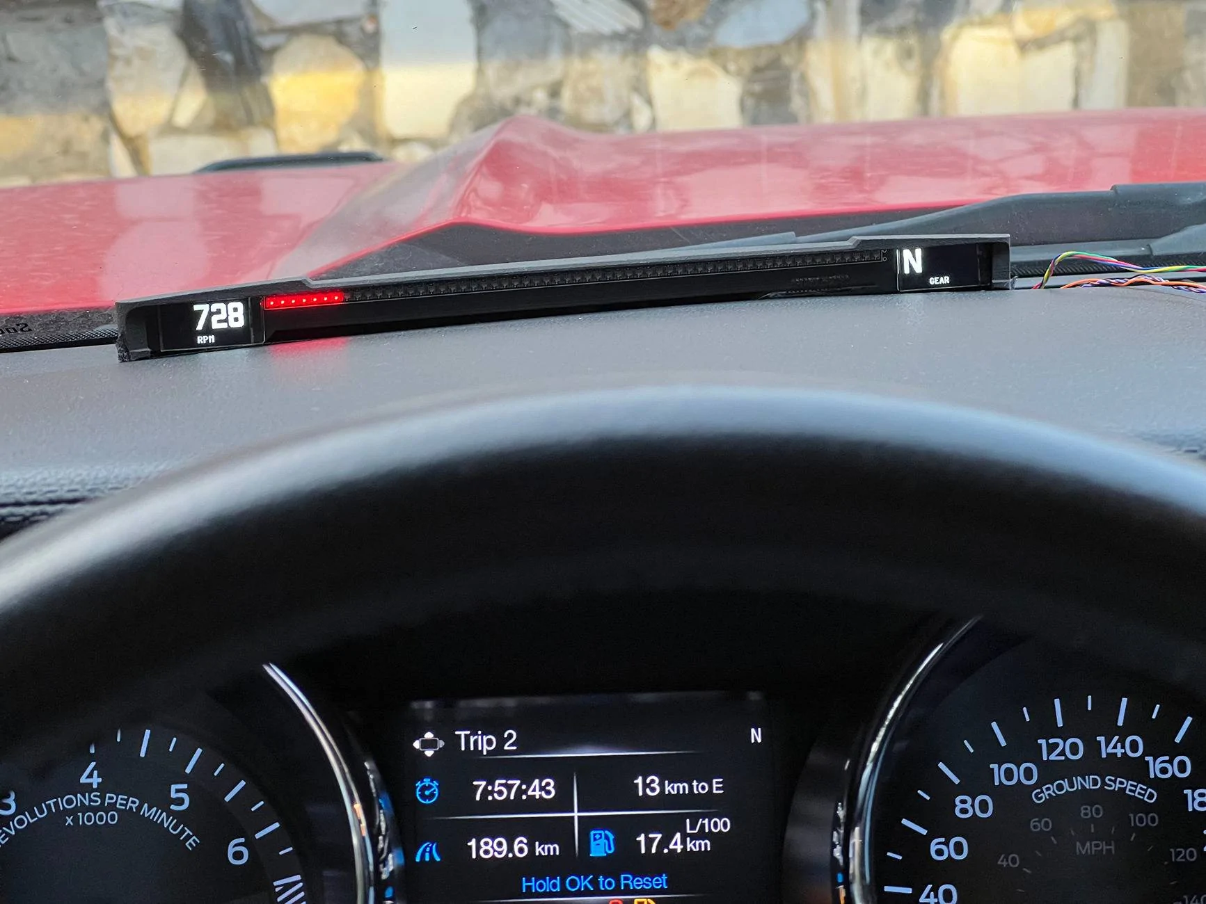
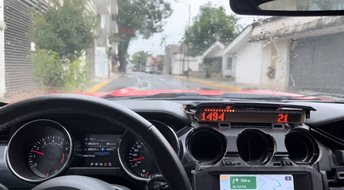
Initially I wanted to make it as HUD device (projecting LED light onto the windshield), but later changed the idea to let it be a face-oriented screen, to avoid issues of bad reflection by the windshield in sunny days.

I visit a local track time to time, not in a sport manner but rather to have fun. When the dashbar shows engine load and current gear, it feels more comfortable to read that info right in front of the eyes rather than look at the instruments cluster. Other aspect - having engine load info on screen it becomes more comfortable to drive in manual gearbox mode in general. You see how much spare power the engine has at current RPM and gear and can decide beforehand if it's time to shift a gear (not my invention, BMW introduced it in 7 series at the beginning of the century). While developing all this stuff more and more ideas were coming, like G-force gauge, timeline graph, live data observation, and of course the shiftlight itself. All these features are organized as presets for drive and sport mode. For example, in D mode it's RPM and speed on the screens and engine power on the LEDs, and in S mode - G-force gauge, shiftlight and current gear.
Technically how the device works - it connects to CAN bus (HS1) in listen-only mode and watches the CAN traffic for all needed information, then populates it on the screens and LEDs bar. I've discovered major part of the HS1 CAN bus of my Mustang GT 2015 (https://github.com/v-ivanyshyn/parse_can_logs/blob/master/Ford CAN IDs Summary.md) and also with the help of friends got logs from GT350 and GT 2020 with 10-speed gearbox. So far the device works with all these cars, in spite that there are differences in CAN data. I haven't had a chance to check it on EcoBoost which would be pretty interesting - for example, to display the boost.
For those who are still interested, let me share all the story...
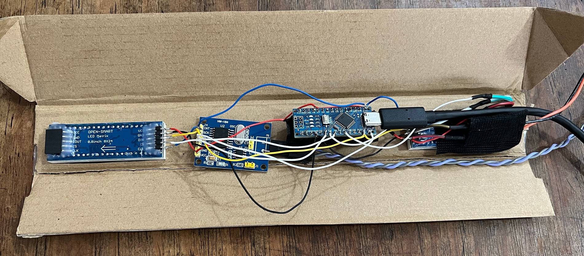
At the very beginning as a proof of concept I built it on Arduino with MCP2551 CAN transmitter and a couple of 8x8 LED boxes. It looks "interesting" from the art perspective, but for sure not fitting into Mustang interior.


Then switched to a concept of a bar that's placed on the torpedo where the factory HUD bar is. 1-2cm of vertical space is perfect for the aesthetic look and functionality. Avoiding going to far too fast, the next step was to utilize STM32 instead of Arduino and prove that OLED displays will work. Here is how this device looked:

Initially I connected it to HS3 CAN behind the instruments panel, but then switched to HS1 bus that goes from the GWM as it's easier to reach. I introduced the harness extension to the rear connector of the GWM and cut my device into it, so the factory harness isn't cut.
After it was proven that STM32 and OLED displays do work, it was time to actually build the device. There are two parts: the electronics and the case. The electronics contains the mainboard and the bar of LEDs and displays. First I developed this mainboard PCB:

Of course, missed some pins, and after inspecting it in hands I changed it a little:

Because the dashbar PCB is a standalone piece, it isn't coupled to the mainboard and may be developed further independently. So far two iterations were enough for good result.
I ordered the PCBs including soldering the components on JLCPCB. For development I used EasyEDA that works pretty well with their service. It took some time to come with a proper list of components that are available on their side, but in result it worth it.
Looking backwards, the issues that caused further iterations were these:
The dashbar body is also an interesting story.
After measuring the bed surface in the car I started with a simple case, assuming that it will only cover the PCBs from top side. I made it in Blender (what a depravity!) and ordered a 3D print on the same JLC site. It became obvious pretty soon that the case should be more solid and enclose the electronics from all the sides. And it became obvious that there will be many iterations to overcome all the issues with fitment, rigidity and usability, so better to rethink which modelling tool to use. In result I switched to Fusion 360 - it provides history of edits and milestones, aside of dedicated to CAD instruments kit.


It took already 7 iterations to make more or less good case. The majority of issues are with rigidity - because the dashbar is long and narrow the 3D printing causes warping. I started with 1 mm wall thickness with additional ribs, but was forced to increase it to 2-3 mm. Another serious issue is environmental conditions - I'm in Mexico and the area under the windshield gets really hot on sunny days. So hot, that once the LEDs from a Chinese LEDs strip desoldered and felt apart. Because of that I chose SLS Nylon material (the 3D printing is made by baking the powder by laser layer by layer, like for rocket engine at SpaceX). This material withstands the temperature and has a high quality look & feel, but it still warps. That's why I changed the design to let the bar PCB be a backbone for the construction, introducing some hooks in the case.
Also, because of hot environment it was a quest to find good material for the screen. I hoped for transparent films, but only acrylic withstands the temperature.
It has been more than half year that I'm developing this dashbar. The majority of time has gone to software part. It's another interesting story - to squeeze out all the juices from the chip performance and memory. A lot of time was spent on refactoring and optimizing open source code that I used, as well as refactoring/extending the application logic. Software engineers will understand it without more explanation and for others it's already boring")
So, the dashbar works, serves my needs on autotrack and highways, brings satisfaction of accomplished work. I was even thinking for perspective to make it a commercial product, but at this moment I lack knowledge in legal area, so maybe in the future... Anyway, if there's someone in Mexico, I can provide it peer-to-peer for testing/trying it out.
Here's a demo video of it's current functionality in fields:
Initially I wanted to make it as HUD device (projecting LED light onto the windshield), but later changed the idea to let it be a face-oriented screen, to avoid issues of bad reflection by the windshield in sunny days.
I visit a local track time to time, not in a sport manner but rather to have fun. When the dashbar shows engine load and current gear, it feels more comfortable to read that info right in front of the eyes rather than look at the instruments cluster. Other aspect - having engine load info on screen it becomes more comfortable to drive in manual gearbox mode in general. You see how much spare power the engine has at current RPM and gear and can decide beforehand if it's time to shift a gear (not my invention, BMW introduced it in 7 series at the beginning of the century). While developing all this stuff more and more ideas were coming, like G-force gauge, timeline graph, live data observation, and of course the shiftlight itself. All these features are organized as presets for drive and sport mode. For example, in D mode it's RPM and speed on the screens and engine power on the LEDs, and in S mode - G-force gauge, shiftlight and current gear.

Technically how the device works - it connects to CAN bus (HS1) in listen-only mode and watches the CAN traffic for all needed information, then populates it on the screens and LEDs bar. I've discovered major part of the HS1 CAN bus of my Mustang GT 2015 (https://github.com/v-ivanyshyn/parse_can_logs/blob/master/Ford CAN IDs Summary.md) and also with the help of friends got logs from GT350 and GT 2020 with 10-speed gearbox. So far the device works with all these cars, in spite that there are differences in CAN data. I haven't had a chance to check it on EcoBoost which would be pretty interesting - for example, to display the boost.
For those who are still interested, let me share all the story...
At the very beginning as a proof of concept I built it on Arduino with MCP2551 CAN transmitter and a couple of 8x8 LED boxes. It looks "interesting" from the art perspective, but for sure not fitting into Mustang interior.
Then switched to a concept of a bar that's placed on the torpedo where the factory HUD bar is. 1-2cm of vertical space is perfect for the aesthetic look and functionality. Avoiding going to far too fast, the next step was to utilize STM32 instead of Arduino and prove that OLED displays will work. Here is how this device looked:

Initially I connected it to HS3 CAN behind the instruments panel, but then switched to HS1 bus that goes from the GWM as it's easier to reach. I introduced the harness extension to the rear connector of the GWM and cut my device into it, so the factory harness isn't cut.
After it was proven that STM32 and OLED displays do work, it was time to actually build the device. There are two parts: the electronics and the case. The electronics contains the mainboard and the bar of LEDs and displays. First I developed this mainboard PCB:

Of course, missed some pins, and after inspecting it in hands I changed it a little:

Because the dashbar PCB is a standalone piece, it isn't coupled to the mainboard and may be developed further independently. So far two iterations were enough for good result.
I ordered the PCBs including soldering the components on JLCPCB. For development I used EasyEDA that works pretty well with their service. It took some time to come with a proper list of components that are available on their side, but in result it worth it.
Looking backwards, the issues that caused further iterations were these:
- power delivery - I didn't take it seriously enough, so the initial variant was overheating
- dashbar PCB components - while the LEDs are placed on the front side, the display surrounding capacitors and resistors are on the rear side. It costs more to order 2-sides soldering on JLCPCB, so I did it on my own. But it' not a good approach, so worth to re-place the components in the future
- too optimistic expectations to get the end-looking PCB - I didn't put enough probes, so figuring out what doesn't work took additional efforts. I was hoping each time that the current version of PCB is the final
The dashbar body is also an interesting story.
After measuring the bed surface in the car I started with a simple case, assuming that it will only cover the PCBs from top side. I made it in Blender (what a depravity!) and ordered a 3D print on the same JLC site. It became obvious pretty soon that the case should be more solid and enclose the electronics from all the sides. And it became obvious that there will be many iterations to overcome all the issues with fitment, rigidity and usability, so better to rethink which modelling tool to use. In result I switched to Fusion 360 - it provides history of edits and milestones, aside of dedicated to CAD instruments kit.


It took already 7 iterations to make more or less good case. The majority of issues are with rigidity - because the dashbar is long and narrow the 3D printing causes warping. I started with 1 mm wall thickness with additional ribs, but was forced to increase it to 2-3 mm. Another serious issue is environmental conditions - I'm in Mexico and the area under the windshield gets really hot on sunny days. So hot, that once the LEDs from a Chinese LEDs strip desoldered and felt apart. Because of that I chose SLS Nylon material (the 3D printing is made by baking the powder by laser layer by layer, like for rocket engine at SpaceX). This material withstands the temperature and has a high quality look & feel, but it still warps. That's why I changed the design to let the bar PCB be a backbone for the construction, introducing some hooks in the case.
Also, because of hot environment it was a quest to find good material for the screen. I hoped for transparent films, but only acrylic withstands the temperature.
It has been more than half year that I'm developing this dashbar. The majority of time has gone to software part. It's another interesting story - to squeeze out all the juices from the chip performance and memory. A lot of time was spent on refactoring and optimizing open source code that I used, as well as refactoring/extending the application logic. Software engineers will understand it without more explanation and for others it's already boring

So, the dashbar works, serves my needs on autotrack and highways, brings satisfaction of accomplished work. I was even thinking for perspective to make it a commercial product, but at this moment I lack knowledge in legal area, so maybe in the future... Anyway, if there's someone in Mexico, I can provide it peer-to-peer for testing/trying it out.
Sponsored
Last edited: