StangTime
Well-Known Member
- Joined
- Apr 16, 2019
- Threads
- 81
- Messages
- 3,594
- Reaction score
- 4,093
- Location
- Ontario 🇨🇦
- First Name
- Todd
- Vehicle(s)
- 19' GT PP1 Manual
- Thread starter
- #1
Well this has been a long time coming. I have built this system in stages over a long period of time. Some of you may have seen these pics before. I wanted to have all the info in one thread and will edit this post as I add more info. At the bottom of this post you will find attachments for some of the CAD drawings I created when I built this system. Feel free to use these and alter for your own system. This build is applicable to the 2018 and up S550 model 9 channel OEM system.
The plan was to build a great sounding, simple-yet-satisfying, system that wouldn't break the bank. The OEM system would be gutted beyond the head unit. Replace the fake 3-way OEM speaker system with a quality, 2-way speaker kit. Keeping it simple with a solid front sound stage, no rear speakers, no dash speaker, no upper door speakers. The head unit signals would run to the spare tire well. A DSP for EQ and time alignment would handle signal processing. The corrected audio signals will go to a 5-channel amp to power everything: The front stage and a removable single 10" subwoofer located behind the rear seats. Did I say it was simple?
Equipment list:
Front stage: Hertz MPK165P.3 Pro
Subwoofer: JL Audio HO110RG-W3v3
DSP: Hertz H8 DSP
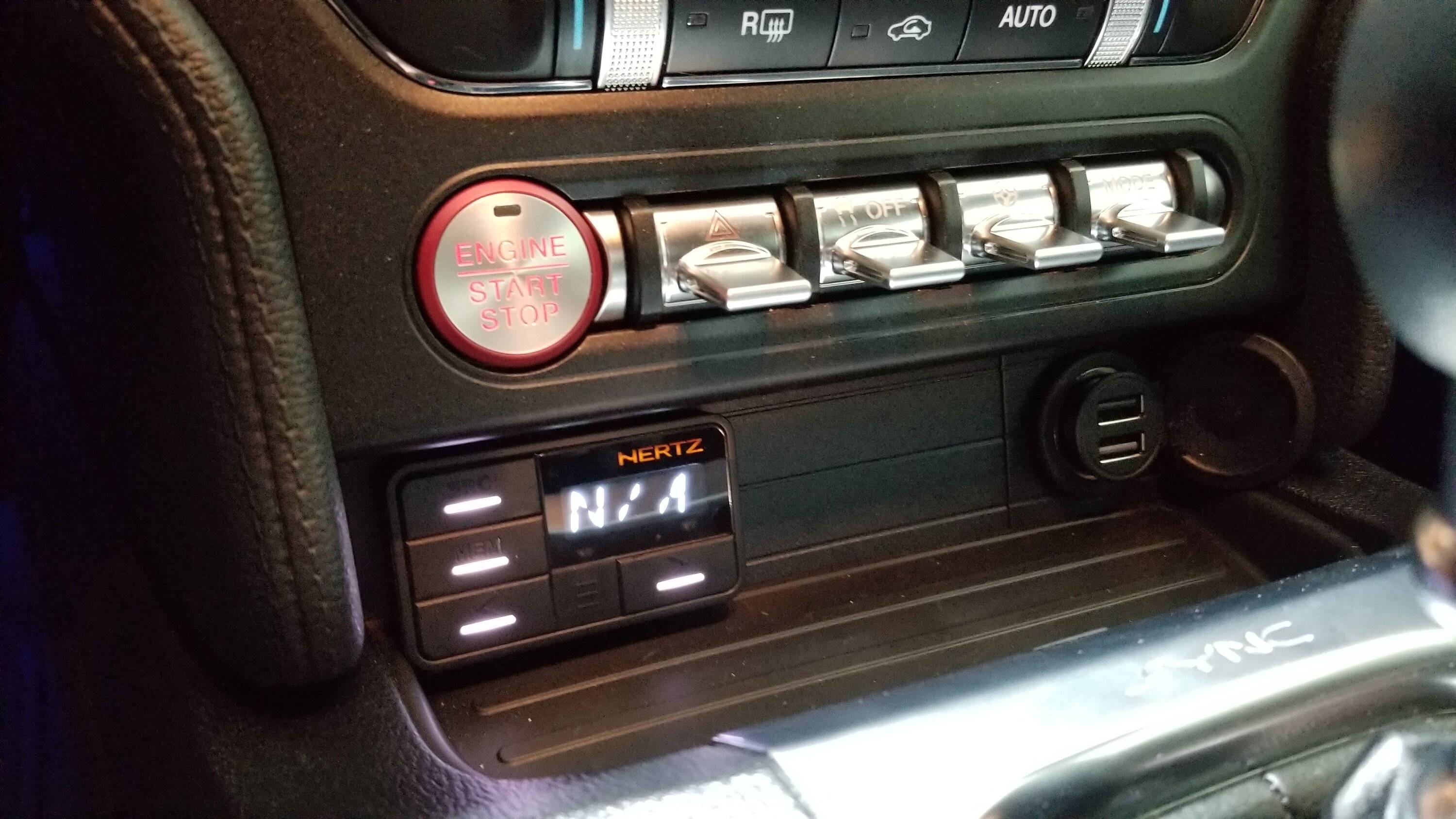
Controller: Hertz DRC HE
Amplifier (5 channel): Hertz HCP 5D
Link to the system wiring diagram: 5-Channel System Wiring
First step: Used Forscan to flatten the output of the head unit so that there is no funky molestation of the audio signal. Note that Ford still applies a variable "loudness" contour to the volume level that gradually decreases as you turn the volume up from 0 to 15 on the dial.
Forscan code in APIM module:
727-01-02 00xx - First two digits set to 0. This disables any EQ Processing, bass roll-off etc. (tone controls will still function as normal)
Interfacing to the head unit:
I made a breakout box for audio signals and speaker wire returns. Completely plug-&-play using Molex sockets, no cutting of any factory wires. Got audio going to my DSP now. Yes, that is Cat6 cable you see for the signal wires. STP (shielded twisted pair) + Metra Speedwire. All wrapped in Tessa tape from beginning to end for a rattle free install. I painstakingly soldered crimp socket pins to all the wires. Slid heat-shrink on, and then inserted the pins onto the short pins of the connectors. Then soldered and shrunk the heat-shrink. The small black wire connects the shields of the signal lines to GND on the brown plug. The connectors all lock together.

I cut a long rectangular hole in a plastic project case and used strain reliefs for the cable exits. Filled the connector area with epoxy.

Then I contorted myself to get under the dash and pull the 9 channel OEM amp out. Removed the amp from the mounting plate and attached my break-out box with some self drilling screws.

Contortion #2 getting the plate mounted back under the dash and connected. Not easy being 6 feet tall and trying to work in this space.

For some deeper information you can rear my other thread here: Wiring guide for non b&o premium audio systems. No LOC required.
Battery Connection:
A KnuKonceptz 4AWG aluminum clad COPPER wire was run down the passenger side away from the audio signals. Fully wrapped in Tessa tape all the way.

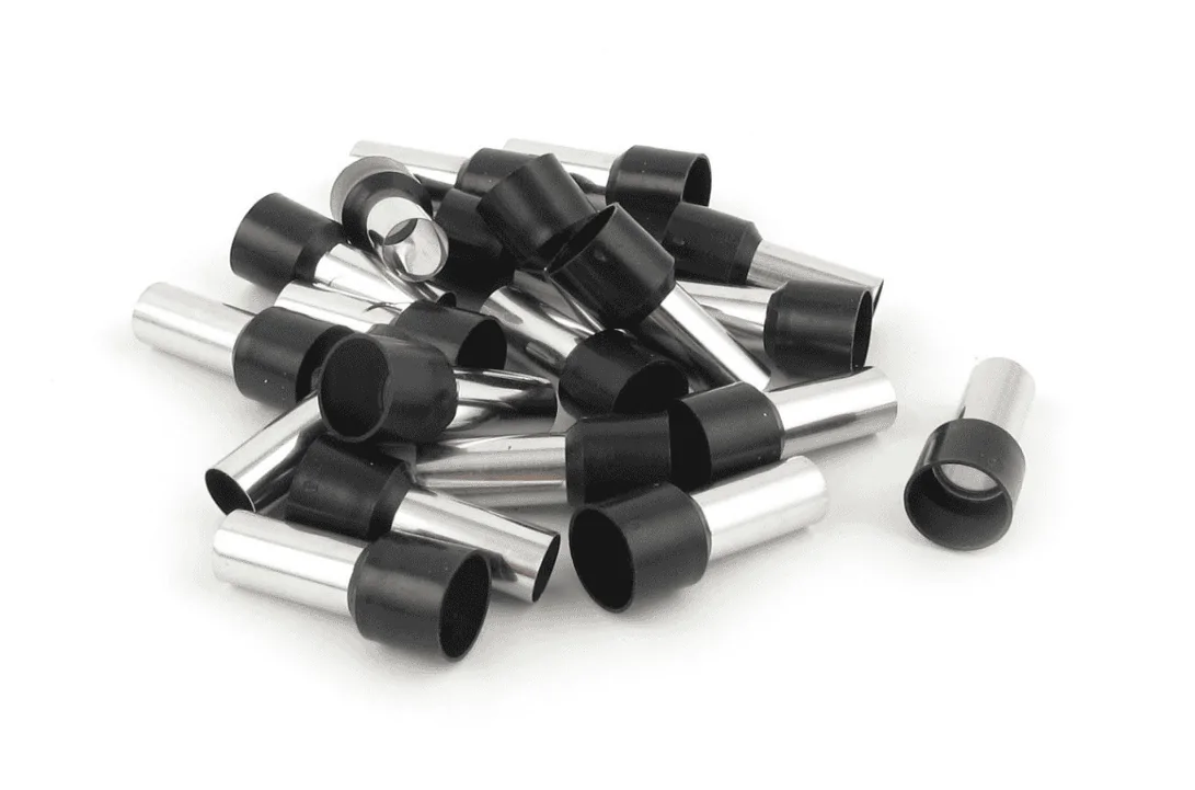
4AWG Wire ferrules. Go on the end of the power wires. They protect the strands when you crank down on the terminal clamping screws. These are Uxcell part# E25-16

Disconnected and removed the battery and tray. Drilled a hole using a step drill just below the cabin air intake. This is the perfect spot as it puts the wire in a very accessible location just above the passenger carpet. The hole is drilled directly across from the threaded nut below the cabin air intake.
A PCV valve grommet sealed the hole and protects the wire. Some Butyl rubber around the wire to prevent water getting in. I may change this in the future to use a proper Nema 6 grade bushing. I routed the power wire to the left to avoid the waterfall spout on the right. The cowl rain tray dumps water into this area so I wanted to avoid it. I drooped the wire downward before going through the firewall so any water that gets on it would have a chance to drip off before the grommet.
I applied wire ferrules appropriate for 4AWG wire onto all ends of the power cable and re-installed the battery. The KnuKonceptz terminals work great with the ferrules. Some red heat-shink insulates the terminal. I flat-block sanded the clamp parts removing the black coating on the mating surfaces (very important) for good conduction. Attached the new terminal with the top clamp nut and trimmed the red rubber to fit over the new assembly.
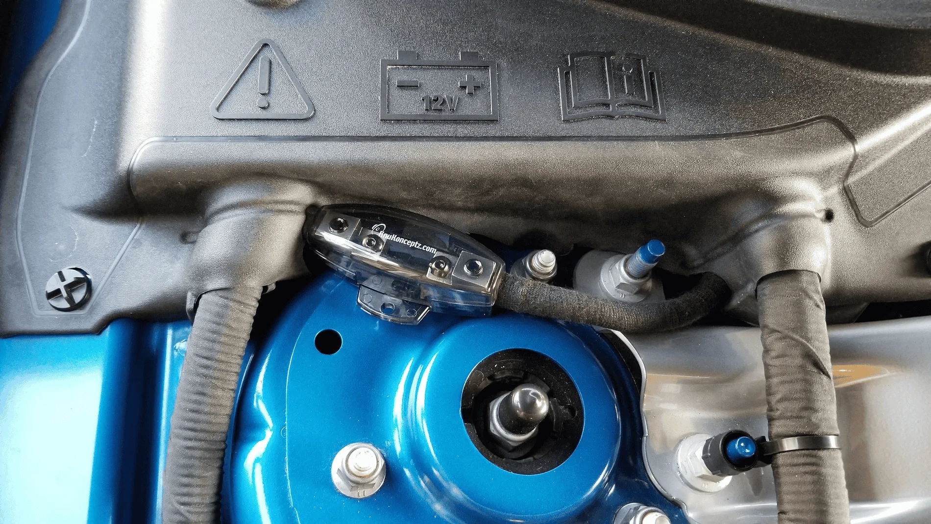
Fuse holder installed (without the fuse!). It looks like a strange position but this was determined the best place after much humming and hawing. The power cable drops down under the negative lead down the side of the battery box.
Trimmed the battery cover a bit to clear the new power wire and fuse holder.
Next up: Speaker install and DSP controller.
The plan was to build a great sounding, simple-yet-satisfying, system that wouldn't break the bank. The OEM system would be gutted beyond the head unit. Replace the fake 3-way OEM speaker system with a quality, 2-way speaker kit. Keeping it simple with a solid front sound stage, no rear speakers, no dash speaker, no upper door speakers. The head unit signals would run to the spare tire well. A DSP for EQ and time alignment would handle signal processing. The corrected audio signals will go to a 5-channel amp to power everything: The front stage and a removable single 10" subwoofer located behind the rear seats. Did I say it was simple?
Equipment list:
Front stage: Hertz MPK165P.3 Pro
Subwoofer: JL Audio HO110RG-W3v3
DSP: Hertz H8 DSP
Controller: Hertz DRC HE
Amplifier (5 channel): Hertz HCP 5D
Link to the system wiring diagram: 5-Channel System Wiring
First step: Used Forscan to flatten the output of the head unit so that there is no funky molestation of the audio signal. Note that Ford still applies a variable "loudness" contour to the volume level that gradually decreases as you turn the volume up from 0 to 15 on the dial.
Forscan code in APIM module:
727-01-02 00xx - First two digits set to 0. This disables any EQ Processing, bass roll-off etc. (tone controls will still function as normal)
Interfacing to the head unit:
I made a breakout box for audio signals and speaker wire returns. Completely plug-&-play using Molex sockets, no cutting of any factory wires. Got audio going to my DSP now. Yes, that is Cat6 cable you see for the signal wires. STP (shielded twisted pair) + Metra Speedwire. All wrapped in Tessa tape from beginning to end for a rattle free install. I painstakingly soldered crimp socket pins to all the wires. Slid heat-shrink on, and then inserted the pins onto the short pins of the connectors. Then soldered and shrunk the heat-shrink. The small black wire connects the shields of the signal lines to GND on the brown plug. The connectors all lock together.

I cut a long rectangular hole in a plastic project case and used strain reliefs for the cable exits. Filled the connector area with epoxy.

Then I contorted myself to get under the dash and pull the 9 channel OEM amp out. Removed the amp from the mounting plate and attached my break-out box with some self drilling screws.

Contortion #2 getting the plate mounted back under the dash and connected. Not easy being 6 feet tall and trying to work in this space.

For some deeper information you can rear my other thread here: Wiring guide for non b&o premium audio systems. No LOC required.
Battery Connection:
A KnuKonceptz 4AWG aluminum clad COPPER wire was run down the passenger side away from the audio signals. Fully wrapped in Tessa tape all the way.

4AWG Wire ferrules. Go on the end of the power wires. They protect the strands when you crank down on the terminal clamping screws. These are Uxcell part# E25-16
Disconnected and removed the battery and tray. Drilled a hole using a step drill just below the cabin air intake. This is the perfect spot as it puts the wire in a very accessible location just above the passenger carpet. The hole is drilled directly across from the threaded nut below the cabin air intake.
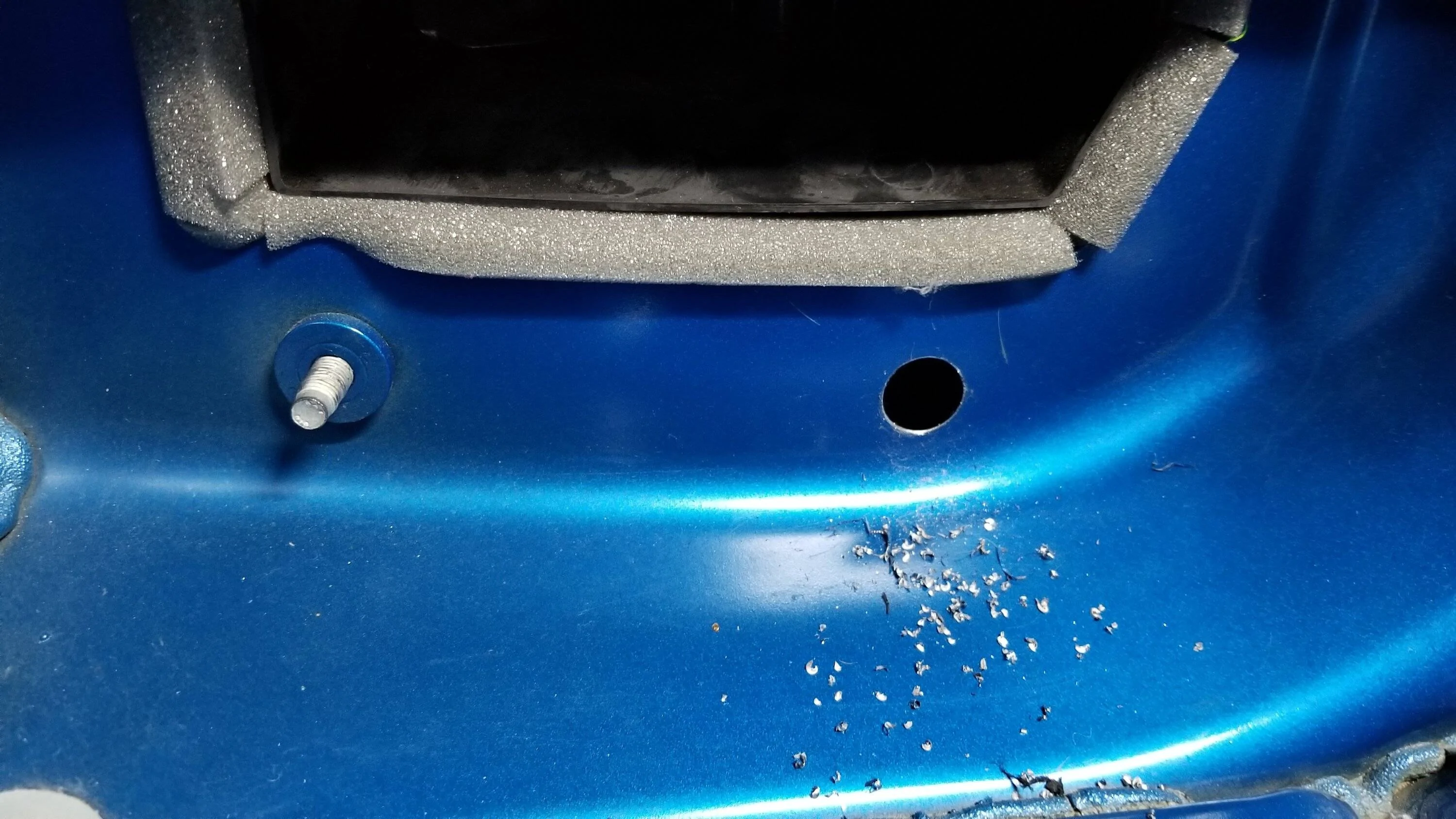
A PCV valve grommet sealed the hole and protects the wire. Some Butyl rubber around the wire to prevent water getting in. I may change this in the future to use a proper Nema 6 grade bushing. I routed the power wire to the left to avoid the waterfall spout on the right. The cowl rain tray dumps water into this area so I wanted to avoid it. I drooped the wire downward before going through the firewall so any water that gets on it would have a chance to drip off before the grommet.

I applied wire ferrules appropriate for 4AWG wire onto all ends of the power cable and re-installed the battery. The KnuKonceptz terminals work great with the ferrules. Some red heat-shink insulates the terminal. I flat-block sanded the clamp parts removing the black coating on the mating surfaces (very important) for good conduction. Attached the new terminal with the top clamp nut and trimmed the red rubber to fit over the new assembly.

Fuse holder installed (without the fuse!). It looks like a strange position but this was determined the best place after much humming and hawing. The power cable drops down under the negative lead down the side of the battery box.

Trimmed the battery cover a bit to clear the new power wire and fuse holder.
Next up: Speaker install and DSP controller.
Sponsored
Last edited: