Sponsored

Reverse Polarity Switch Wiring Help

Deleted member 69311

Guest
Hey there!

I have a set of 2018 GT350 mufflers with the actuators. My GT is a base 2018. I don’t have the plug in the back for any A/E.

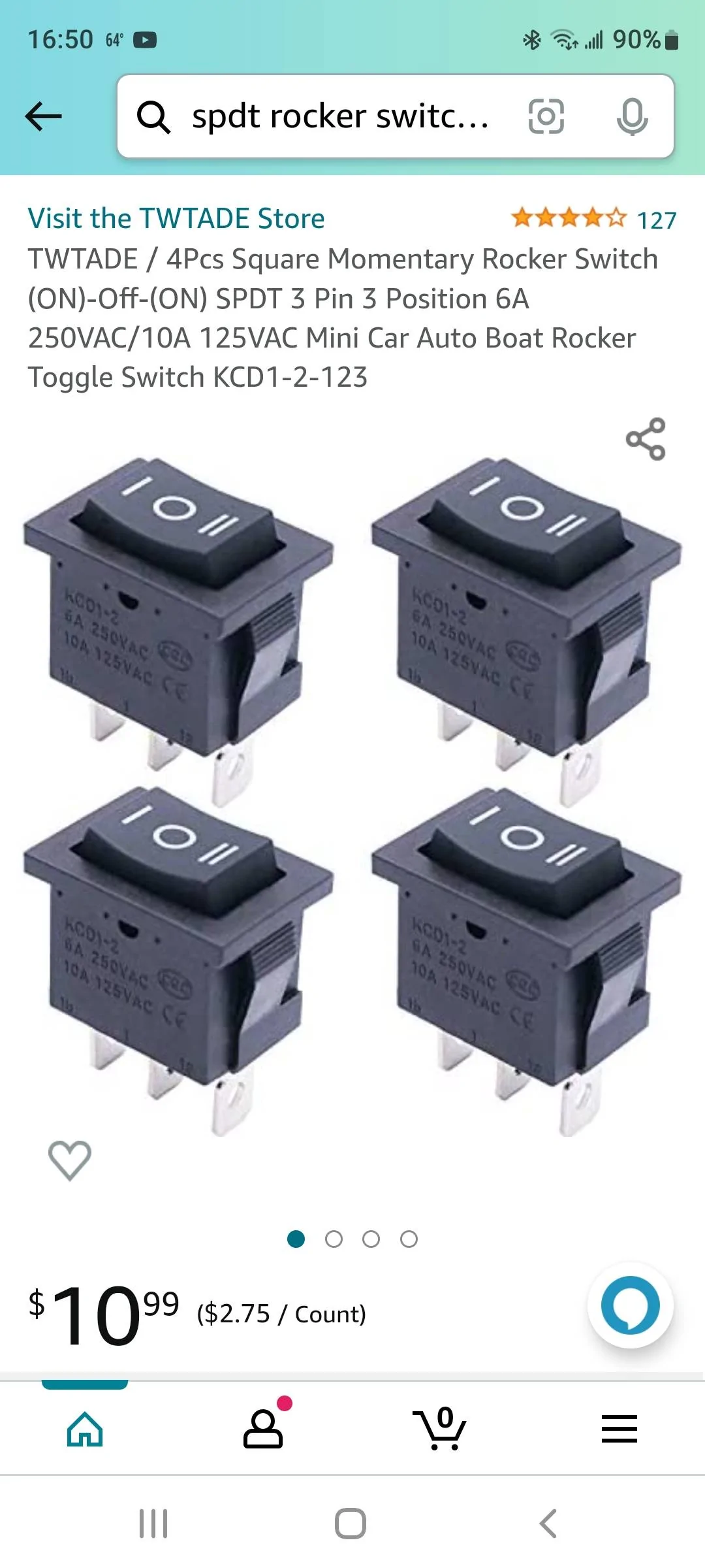
I am trying to figure out how to wire a momentary reverse polarity rocker switch. I wired up this switch I got from Amazon (see photos), but I’m not sure if I’m doing it right.

Based on the video I’ve seen, and my own understanding, it’s a 3-wire system.
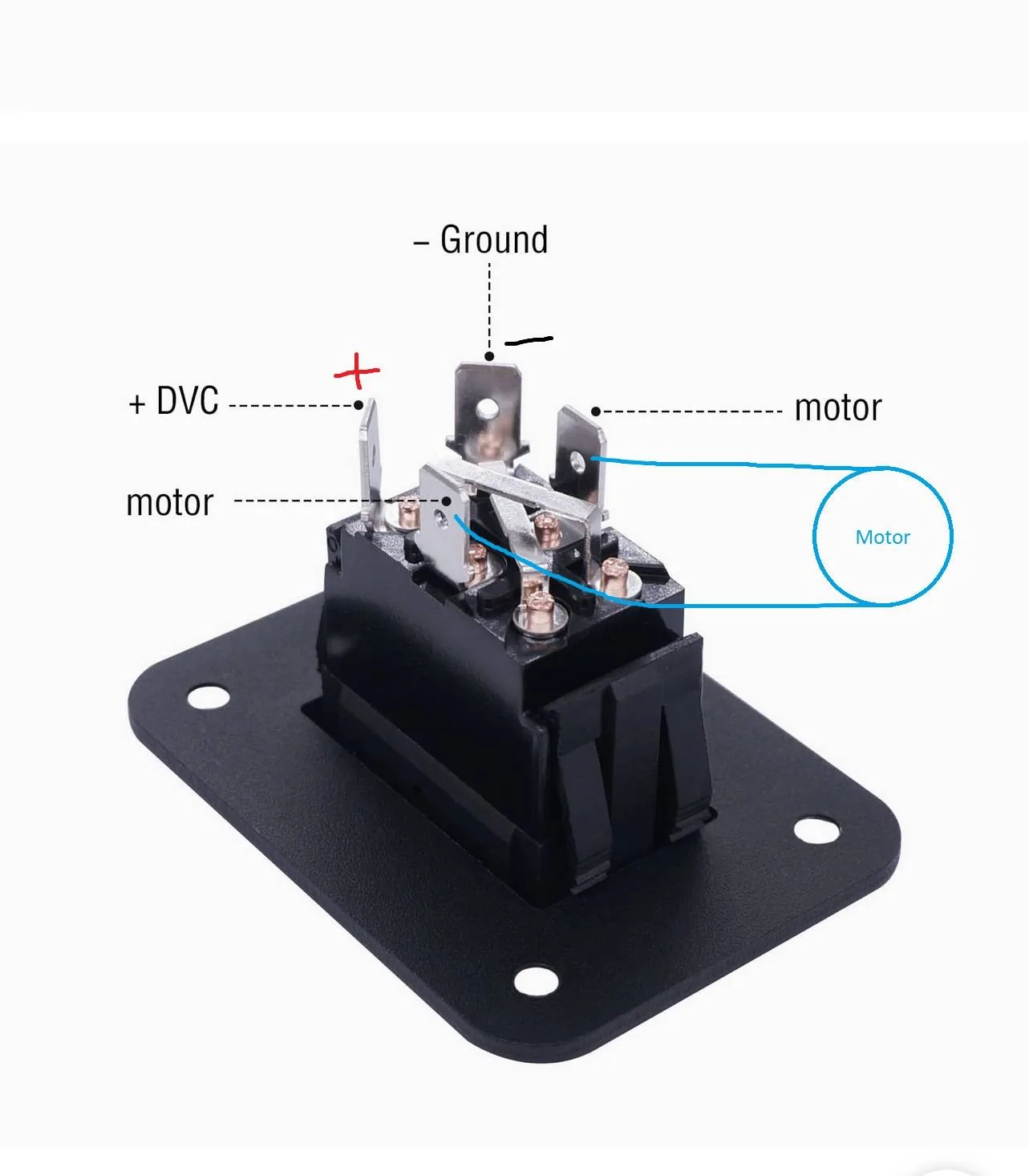
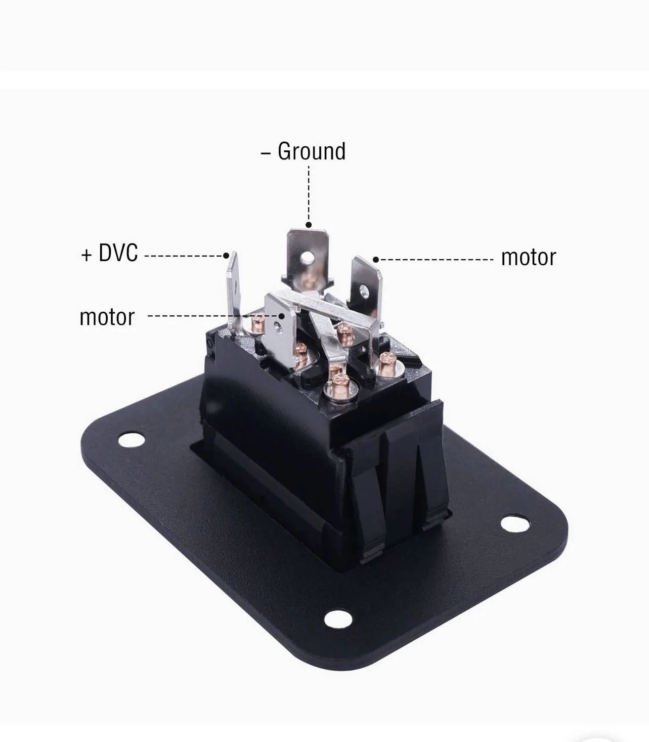
  • Positive wires (#3) connect together and get direct power (not wired up to the switch)
  • Negative wires (#1) gets wired up to the negative terminal of the switch
  • Switch wires (#2) also gets wired up to a negative terminal of the switch (negative switched)
The problem I’m facing is that I am able to get the actuators closed, but i can’t get them to open without pushing down on the rocker switch, then with my other hand, taking the switch wires (#2) and touching them directly to the ground wires (#1). How can I wire this so that when I press open, the switch connection somehow makes contact with the negative terminal and makes it open?

Am I using the wrong switch? How can I wire this up correctly? If anyone can walk me through this, that’d be greatly appreciated! Thank you!

A695403C-7451-4FC9-965B-5C6176B670FF.webp


7F51EEBF-8690-47E2-80C4-D1A9CC76AA09.webp
Sponsored


ORRadtech

Well-Known Member
Joined
Sep 12, 2019
Threads
25
Messages
4,049
Reaction score
3,987
Location
Atlanta, Georgia
First Name
Dave
Vehicle(s)
18 Mustang EcoBoost convertible, 14 Ford Fusion SE
Without knowing for sure the schematic for that switch, and the positive post is confusing, I'll tell you how I'd do it. Keep in mind that I've not messed with a system like this and am basing my thoughts on what you have posted.

A positive 12v wire from the car should be connected together with the positive wires of the actuators and not be connected to a switch.
You need a single pole/double throw switch of your choosing.
On that switch a wire needs to run from a vehicle ground to the common pole of the switch. Then a wire from each of the other two switch terminals needs to go to the negative wire on each actuator.

I'm unsure if the switch you have is suitable for what you want to do. It's definitely overkill though. I'd think something like this is all you would need.
Screenshot_20221029-165005_Amazon Shopping.webp
 

Jaymar

Well-Known Member
Joined
Jun 15, 2018
Threads
3
Messages
1,216
Reaction score
1,432
Location
Portland, OR
First Name
Jaymar
Vehicle(s)
2022 GT/CS - Rapid Red
If the switch is the same as what is pictured it takes the place of the reversing polarity relays described above and will operate just like a standard 5 wire door lock circuit. Hook it up as labeled with +12V to the terminal labeled positive, ground going to ground and the two motor wires going to each lead of the motor. This assumes the actuator is a two wire direct link to the motor.
 

Sponsored

5doorsoffury

Well-Known Member
Joined
Jun 26, 2022
Threads
3
Messages
245
Reaction score
305
Location
a forsaken branch of the wavefunction called ny,
First Name
this guy
Vehicle(s)
mustang gt
Try a 451m from dei. i used them to add power locks for all kinds of cars. there driven with a negitive trigger and a 12v power lead. they can be done with 2 relays as well.
 

GMB Racing

Well-Known Member
Joined
Jul 13, 2015
Threads
21
Messages
243
Reaction score
180
Location
nh
Vehicle(s)
15 GT, 16 Escape, 21 F250 (all Ruby Red)
Vehicle Showcase
1
Jarmar has it right, you need it to have motor wires connected to the center terminals and pwer on one side and ground on the other
 
OP
OP

Deleted member 69311

Guest
If the switch is the same as what is pictured it takes the place of the reversing polarity relays described above and will operate just like a standard 5 wire door lock circuit. Hook it up as labeled with +12V to the terminal labeled positive, ground going to ground and the two motor wires going to each lead of the motor. This assumes the actuator is a two wire direct link to the motor.
The wiring isn’t going directly to the motors. I spliced the harness wiring and attached wires to that. Here’s how the actuators work with the 3 pin harness.
This YouTube video shows how it works, I’m just having a hard time understanding how we wired it because he didn’t show it.
 

Jaymar

Well-Known Member
Joined
Jun 15, 2018
Threads
3
Messages
1,216
Reaction score
1,432
Location
Portland, OR
First Name
Jaymar
Vehicle(s)
2022 GT/CS - Rapid Red
Well, if you can trust that guy, I don't but it's all we have, then 1 and 3 go to your power and ground as specified. Then throw away the switch you have because it won't do you any good. You will then need a SPST switch that latches (so, not momentary) to connect 2 to ground when you want it one condition. You then flip the switch to remove ground from 2 to get the other condition.
 
OP
OP

Deleted member 69311

Guest
Well, if you can trust that guy, I don't but it's all we have, then 1 and 3 go to your power and ground as specified. Then throw away the switch you have because it won't do you any good. You will then need a SPST switch that latches (so, not momentary) to connect 2 to ground when you want it one condition. You then flip the switch to remove ground from 2 to get the other condition.
I really appreciate your help! Would a latching switch like this work? I tried out the momentary switch (apparently I don’t need a momentary switch) from the same company, but it wouldn’t work. Maybe I wired it wrong? I can purchase the same switch but latching.
I followed their #1 diagram and the light came on every time I pressed the button, but nothing was activated in the actuators.

104A65E9-7AE8-4498-AE0E-771C7AA7C055.jpeg


36B2A279-5FD6-4F52-A6F3-B4FF43FF967F.webp
 

Jaymar

Well-Known Member
Joined
Jun 15, 2018
Threads
3
Messages
1,216
Reaction score
1,432
Location
Portland, OR
First Name
Jaymar
Vehicle(s)
2022 GT/CS - Rapid Red
I really appreciate your help! Would a latching switch like this work? I tried out the momentary switch (apparently I don’t need a momentary switch) from the same company, but it wouldn’t work. Maybe I wired it wrong? I can purchase the same switch but latching.
I followed their #1 diagram and the light came on every time I pressed the button, but nothing was activated in the actuators.

104A65E9-7AE8-4498-AE0E-771C7AA7C055.jpeg


36B2A279-5FD6-4F52-A6F3-B4FF43FF967F.jpeg
That should work, as long as it's latching. Otherwise it will only open or close the valve while you're holding the button.
Sponsored


Top