law242
Well-Known Member
- Thread starter
- #1
hello all! I started this project because I have a 15 premium with the 9 speaker Shaker. Overall the sound sounds good to me but it always lacked base. I work in IT and I can regularly have lots of computers or voip phones in my trunk and wanted a solution that took as little space as possible. The further complication is that I have a spare tire kit in my car, so where to put the amp? Well I decided that I wanted to design a box that not only was removable when I needed that last bit of space but also would contain the amplifier as well. I also ensured I could open the spare tire cover at all times as well.
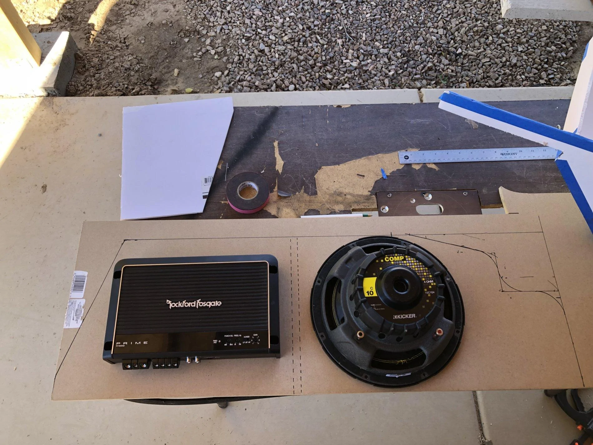
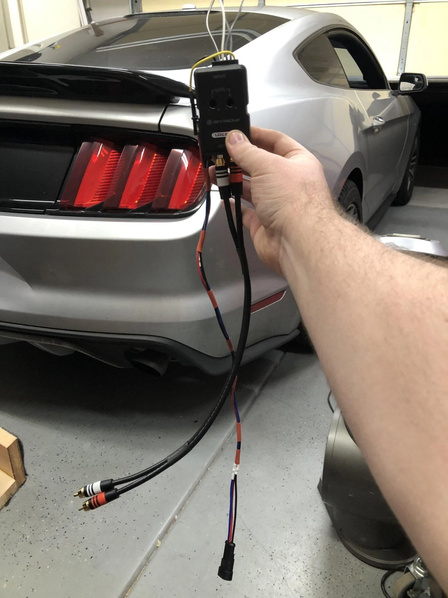
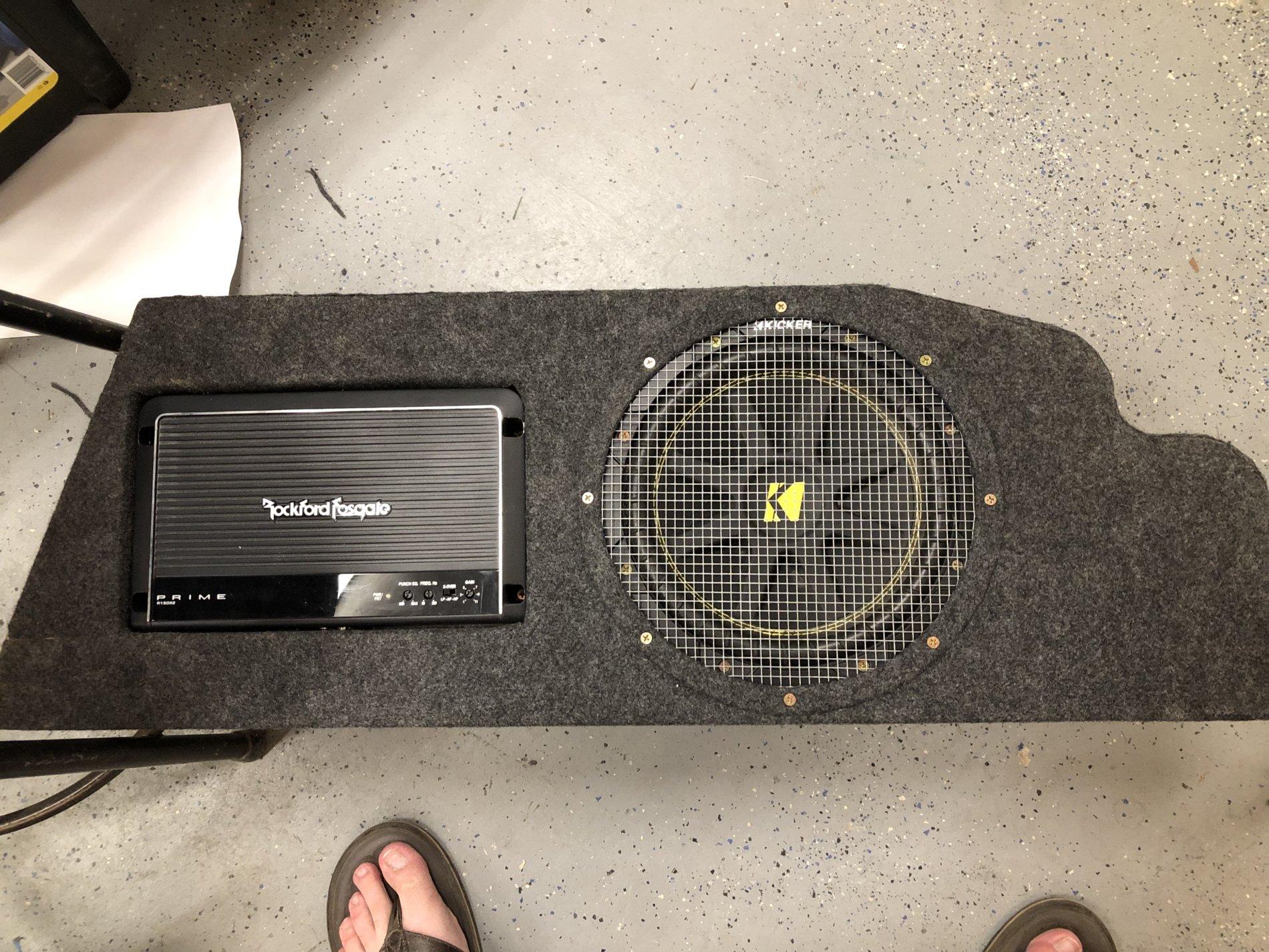
Components I used were a Kicker Comp C 10, originally a rockford r150x2, replaced with a rockford r250x1, and the line out converter I used was a Skoche loc2sl
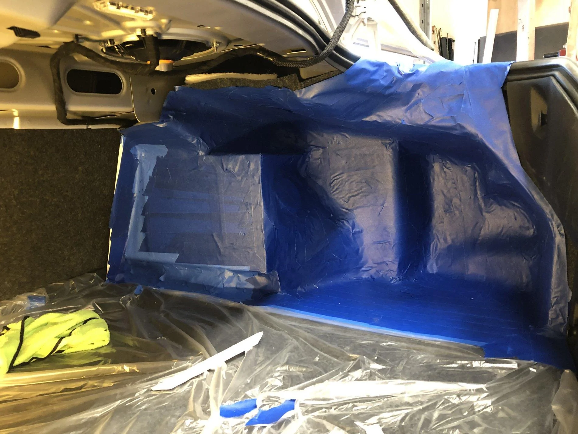
I first had a grand idea I would build it out of fiberglass, and when I started making it I misunderstood the instructions and did not put enough hardener. Which left me with a partially cured initial mold that was worthless. Upon my fathers advice I scrapped that project and decided to do it out of wood. Please enjoy the progress pictures.
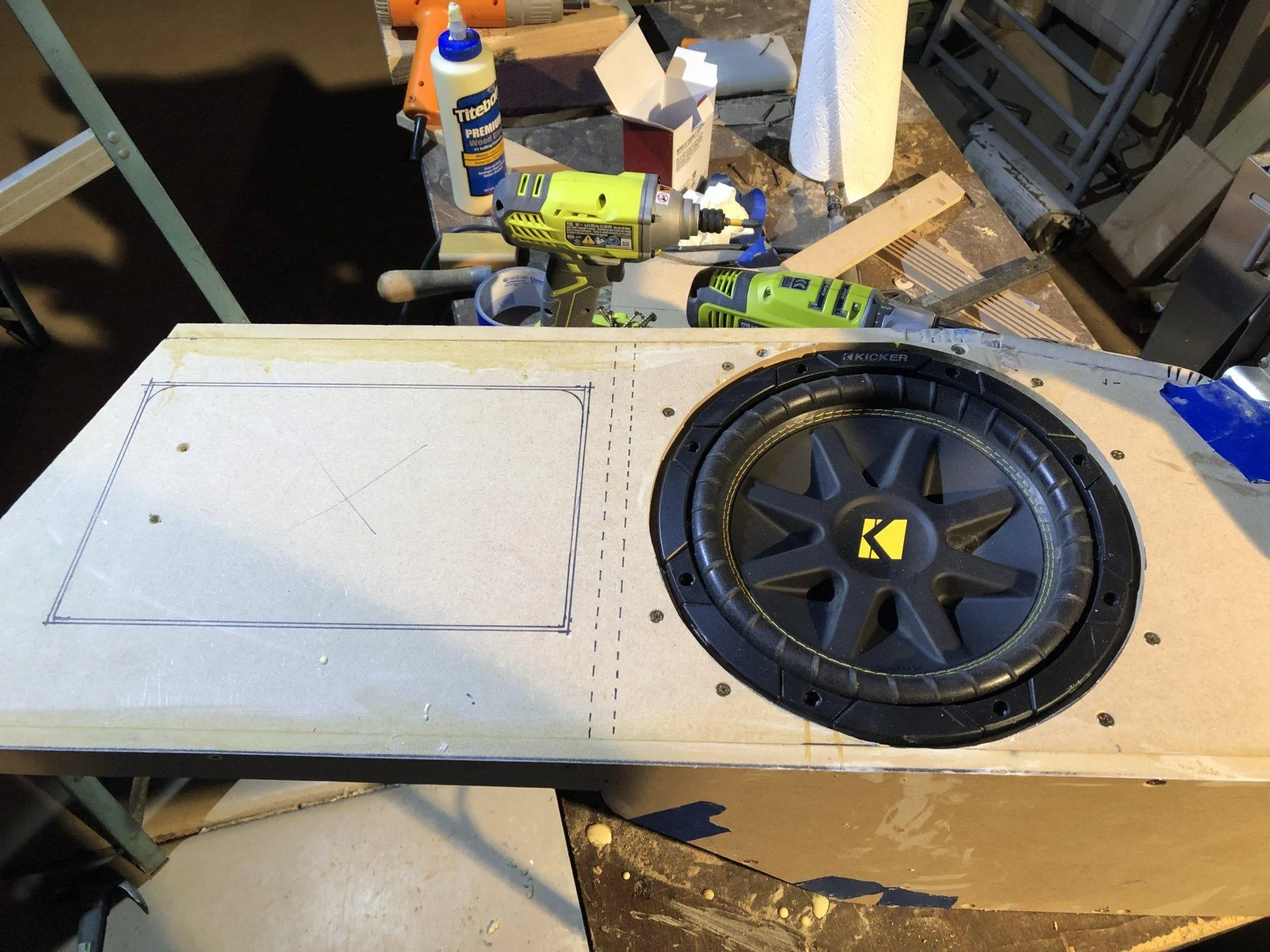
In this photo I had laid out a flat section in which the amp would mount and the wiring could reside behind in the box.

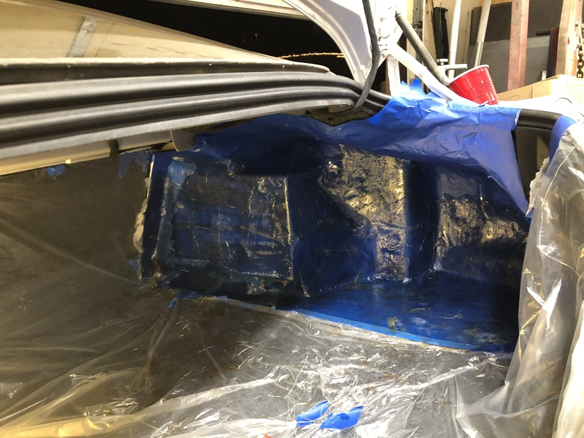
After I laid the fiberglass it was evident I did not put enough hardener..
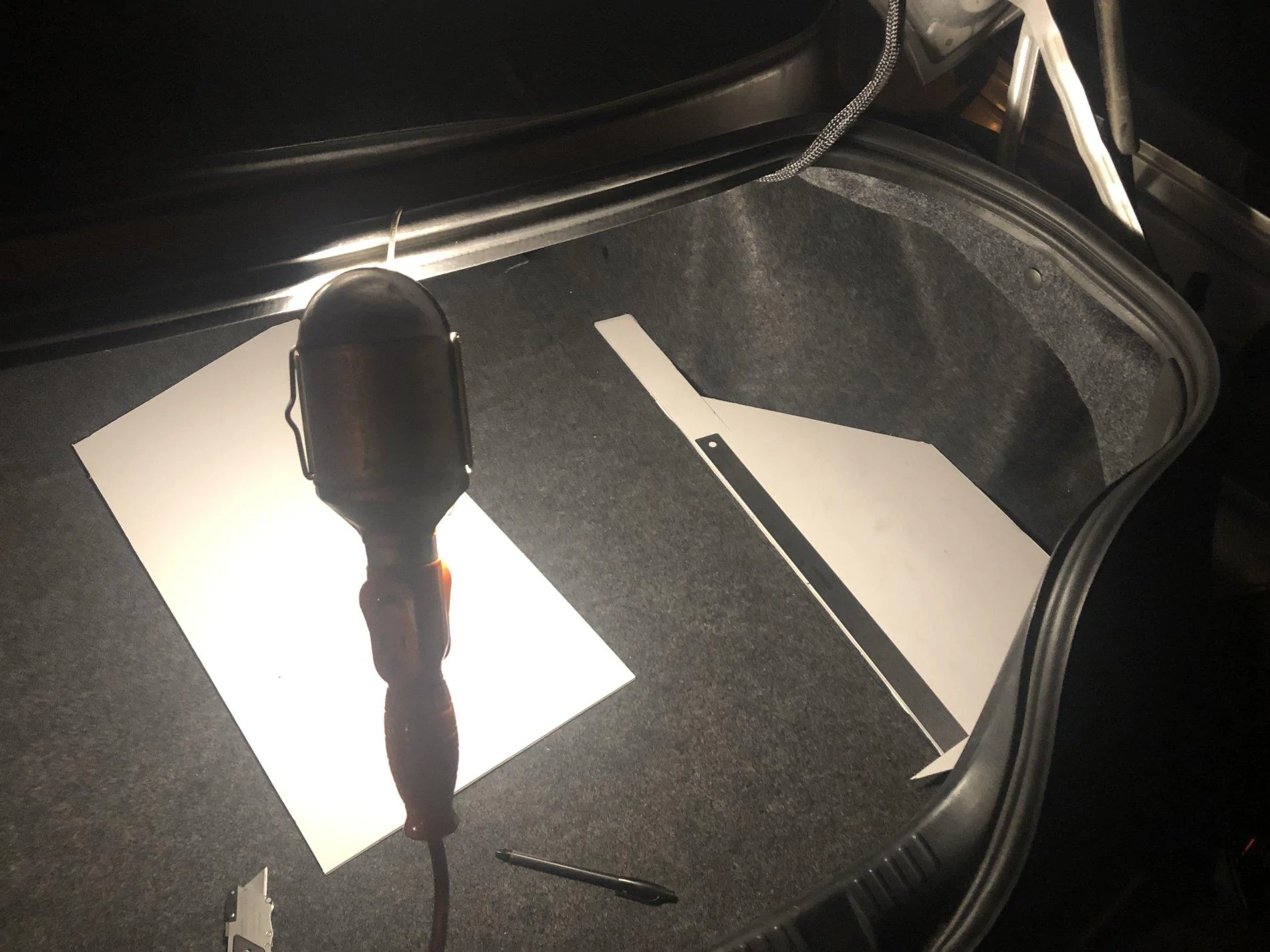
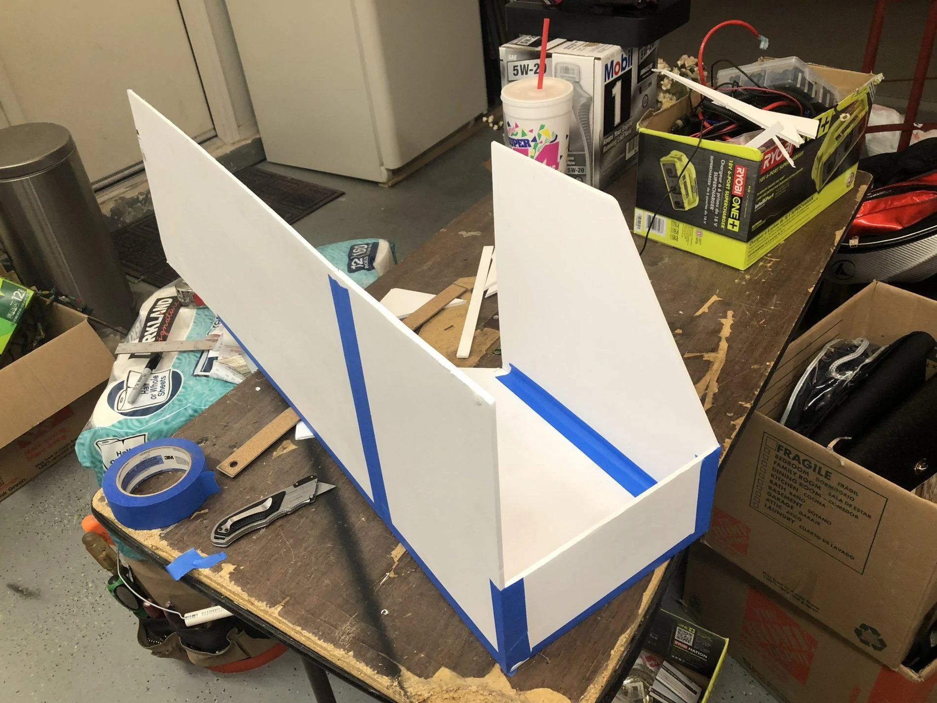
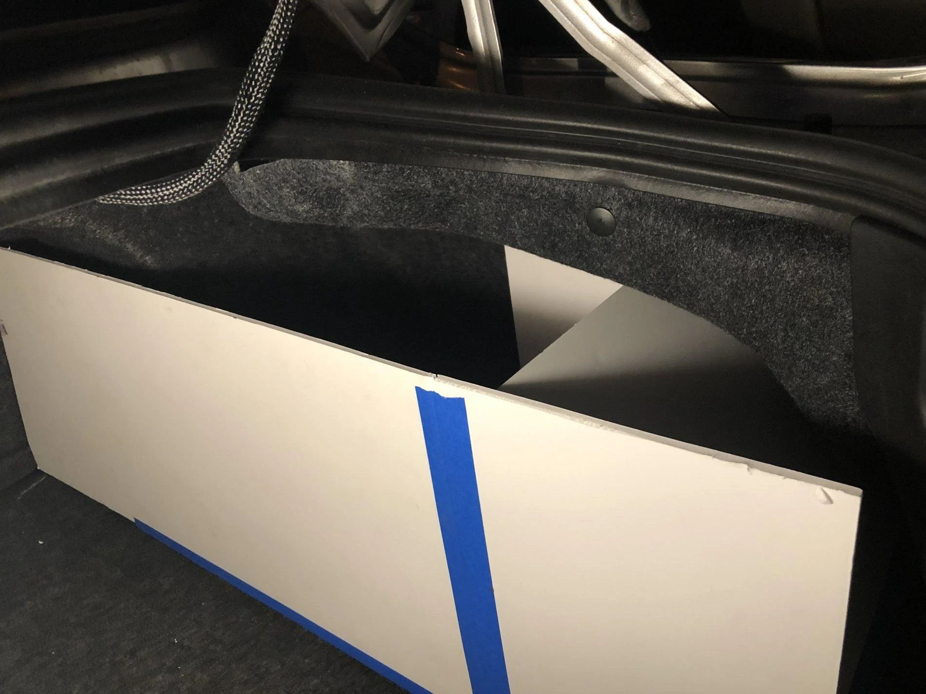
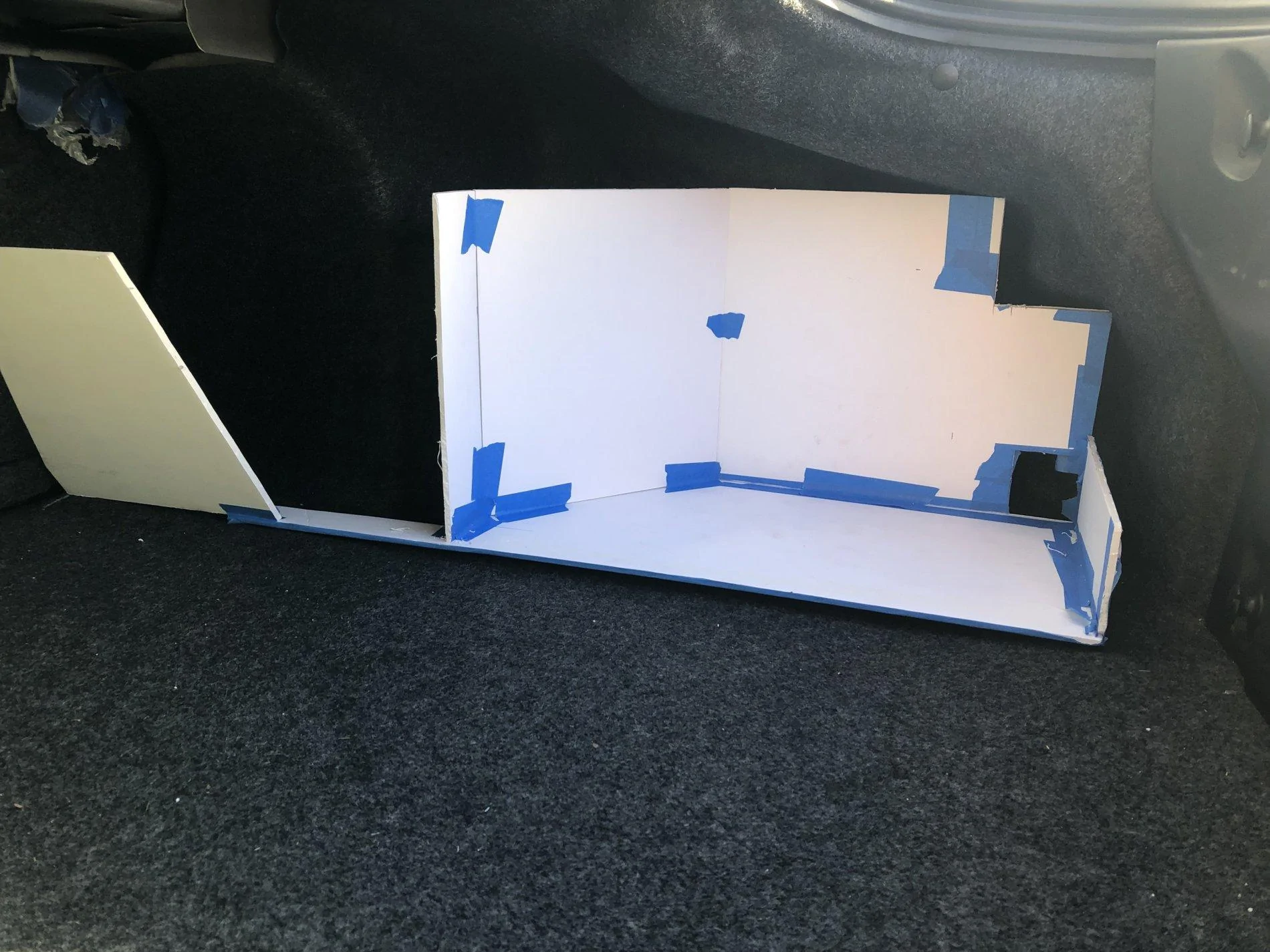
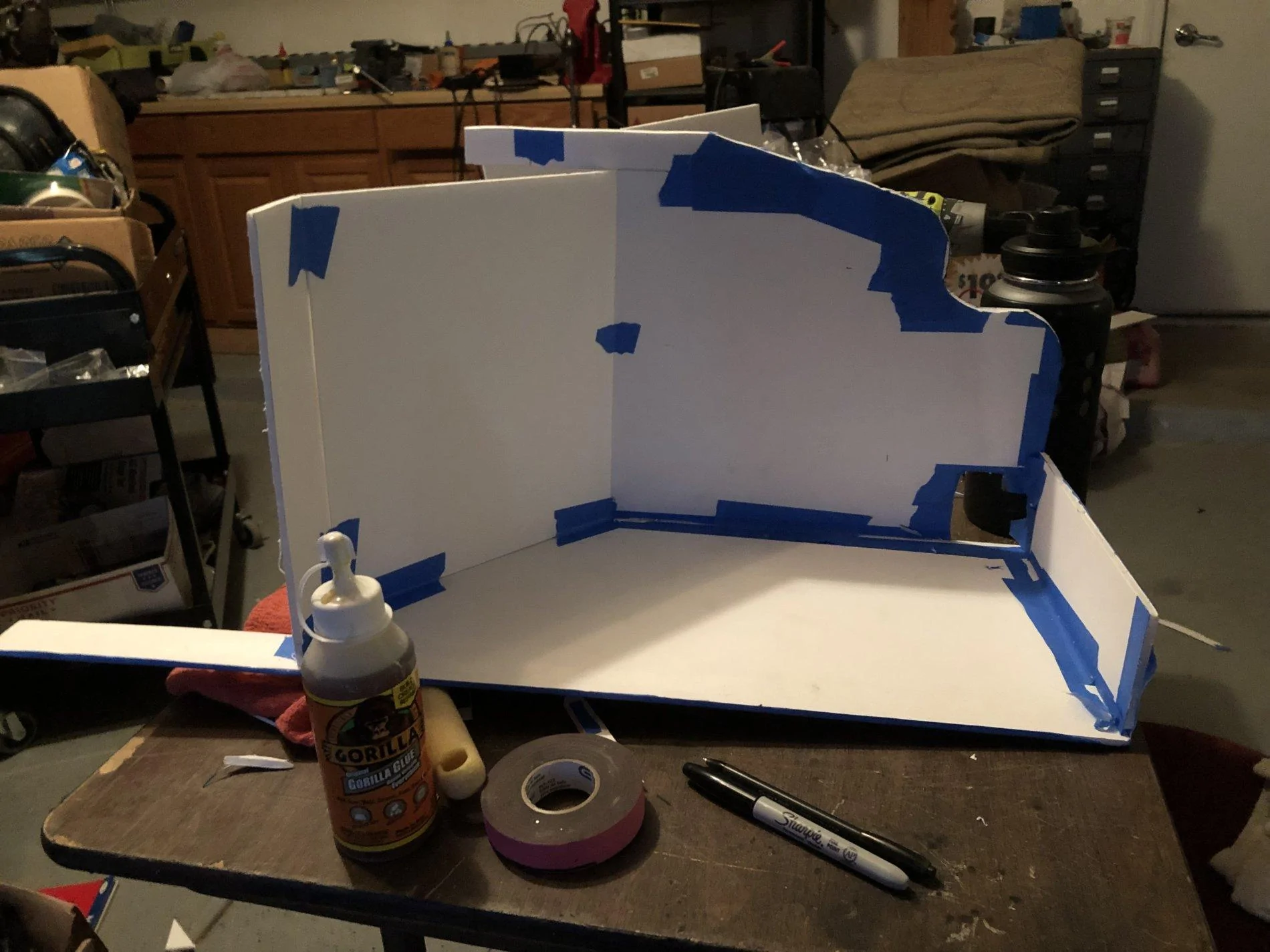
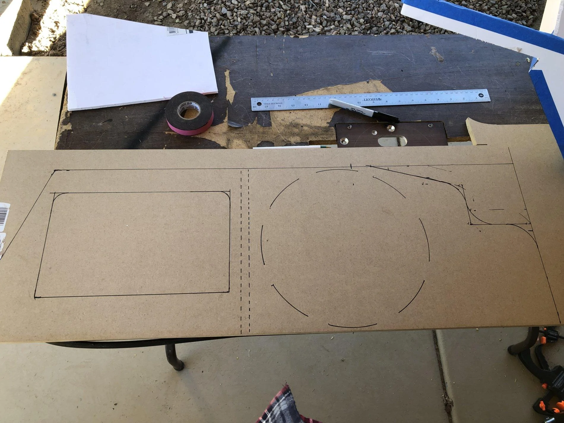
So I took my fathers advice and scrapped the project. I then used presentation board to start prototyping the wood box I would make.
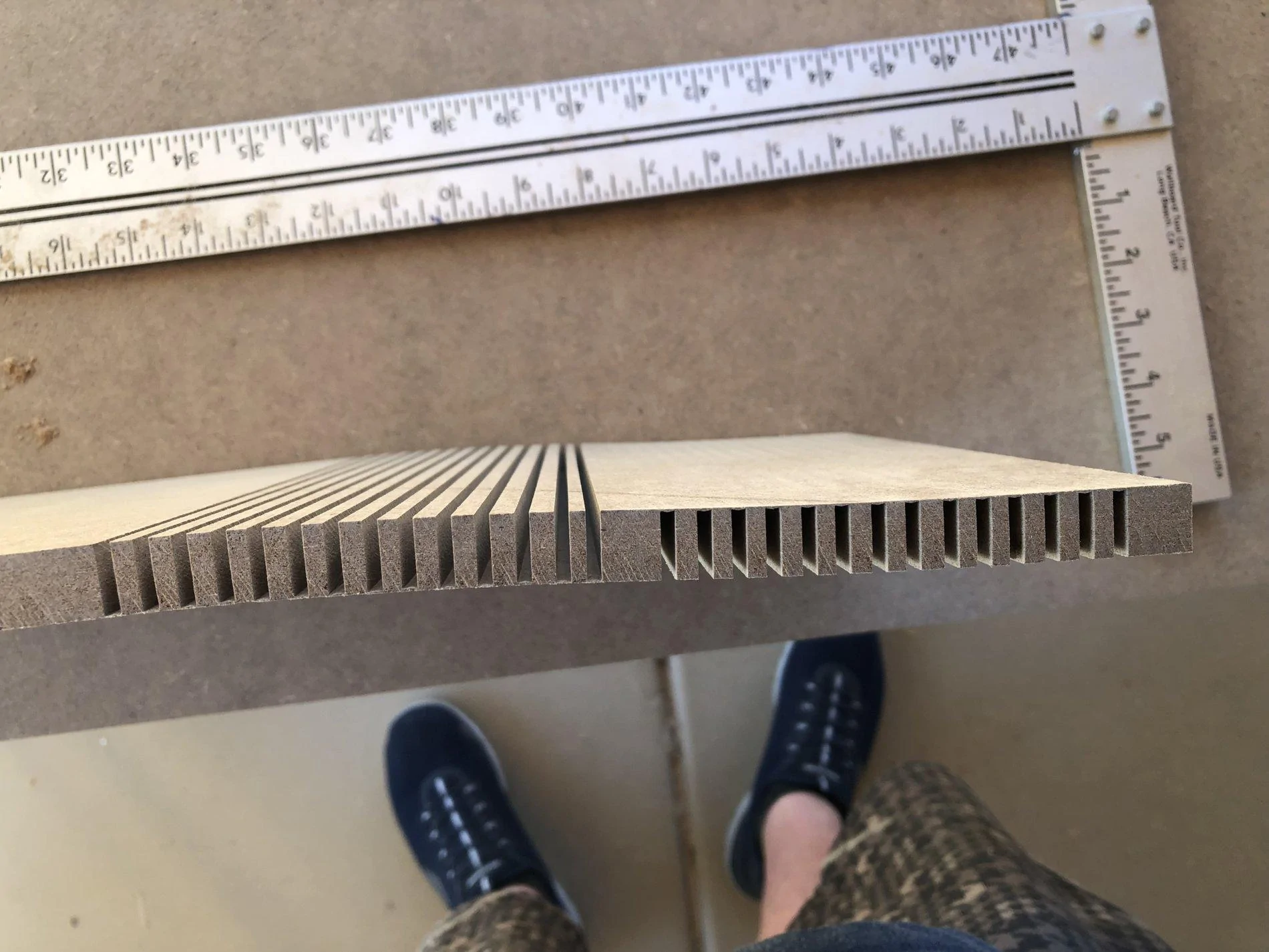
The next challenge was that I was wanting to be able still do nice bends for a tight fit, so I researched something called kerfing. It is the cutting of wood in slices to where you can bend it into shapes. So I started practicing.

After I felt comfortable with this I started cutting out the actual box.
I knew I wanted the back section to fit nice and tight so I integrated kerf's into that as well.
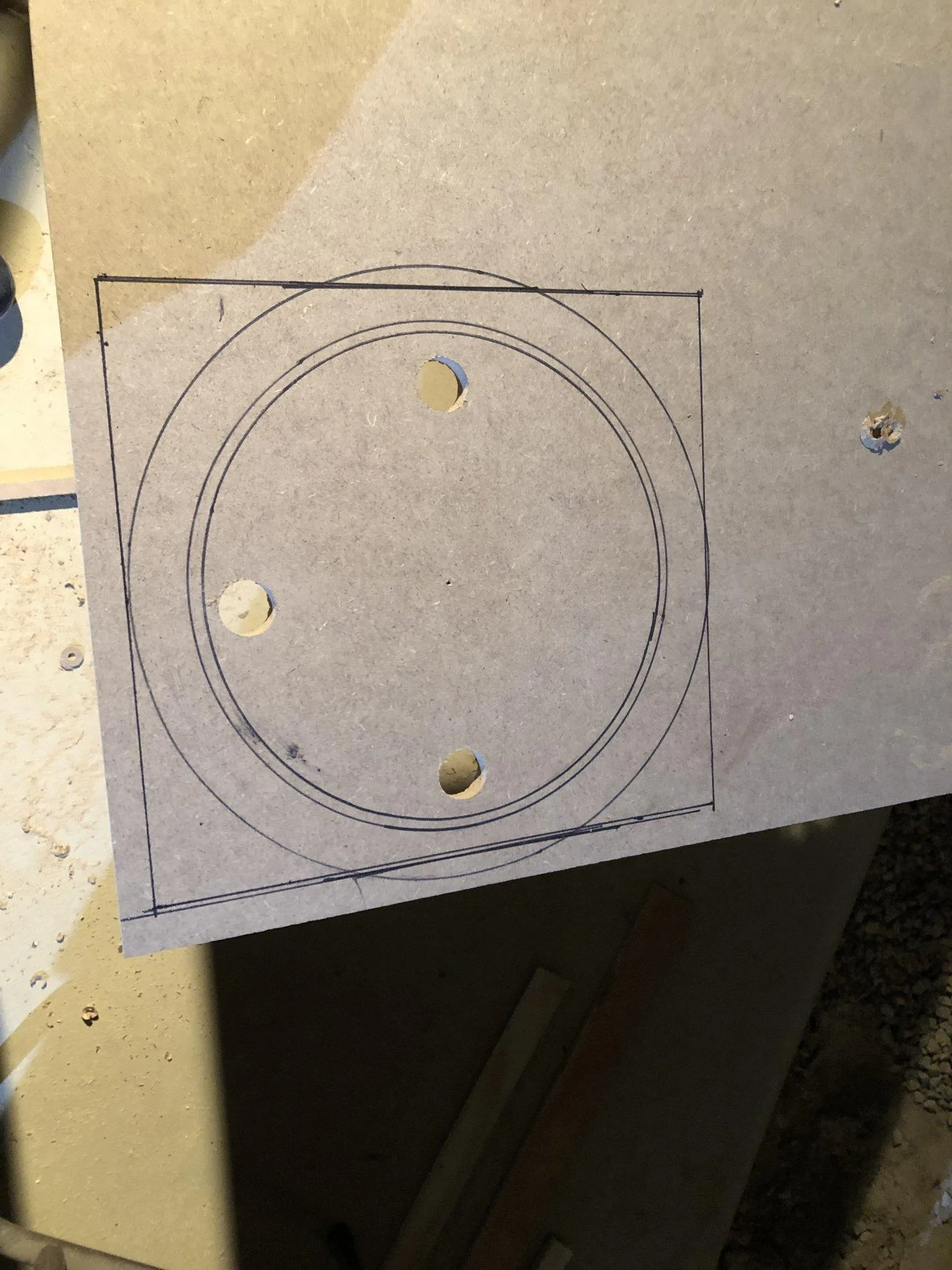
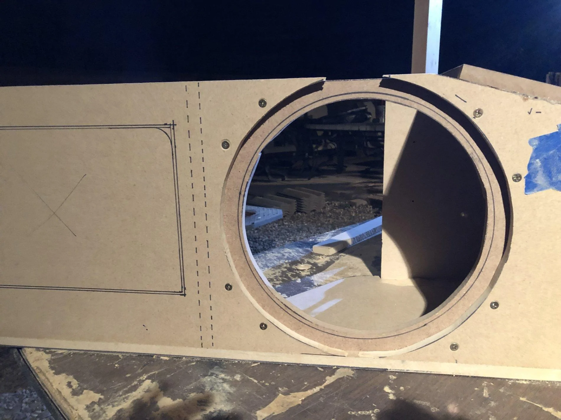
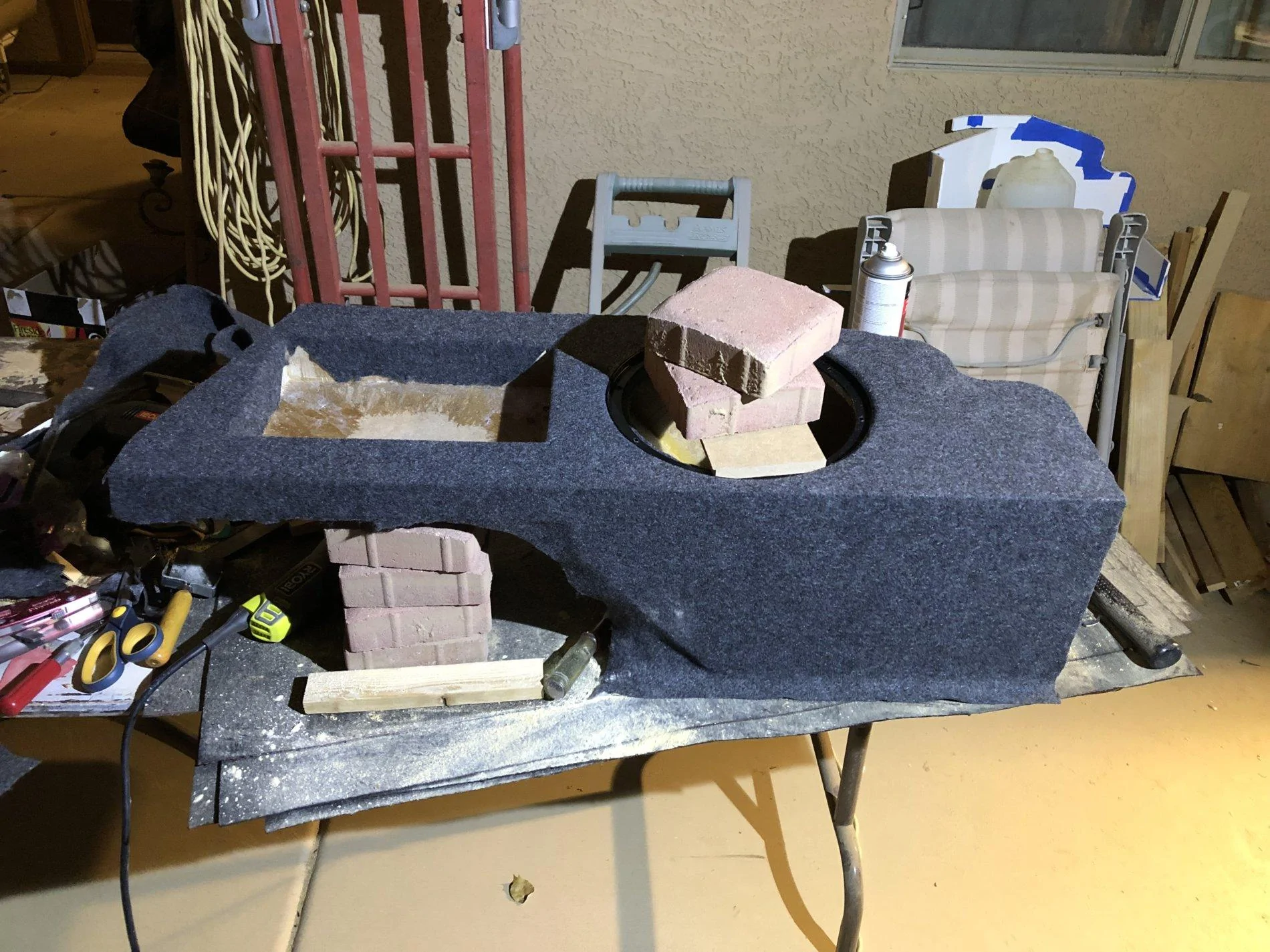
As I got closer to finishing the box I finally started making the cavity for the amp.
Then came carpeting and making sure the box was sealed good.
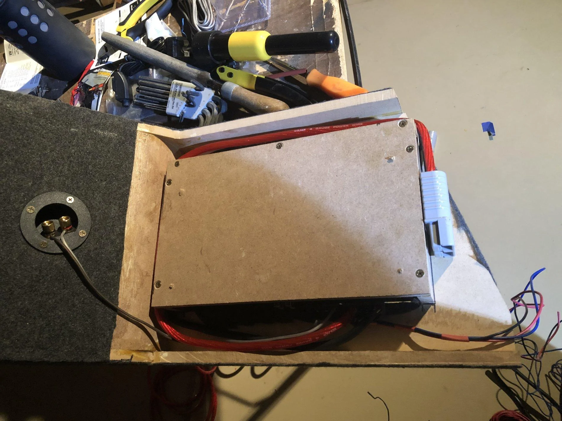
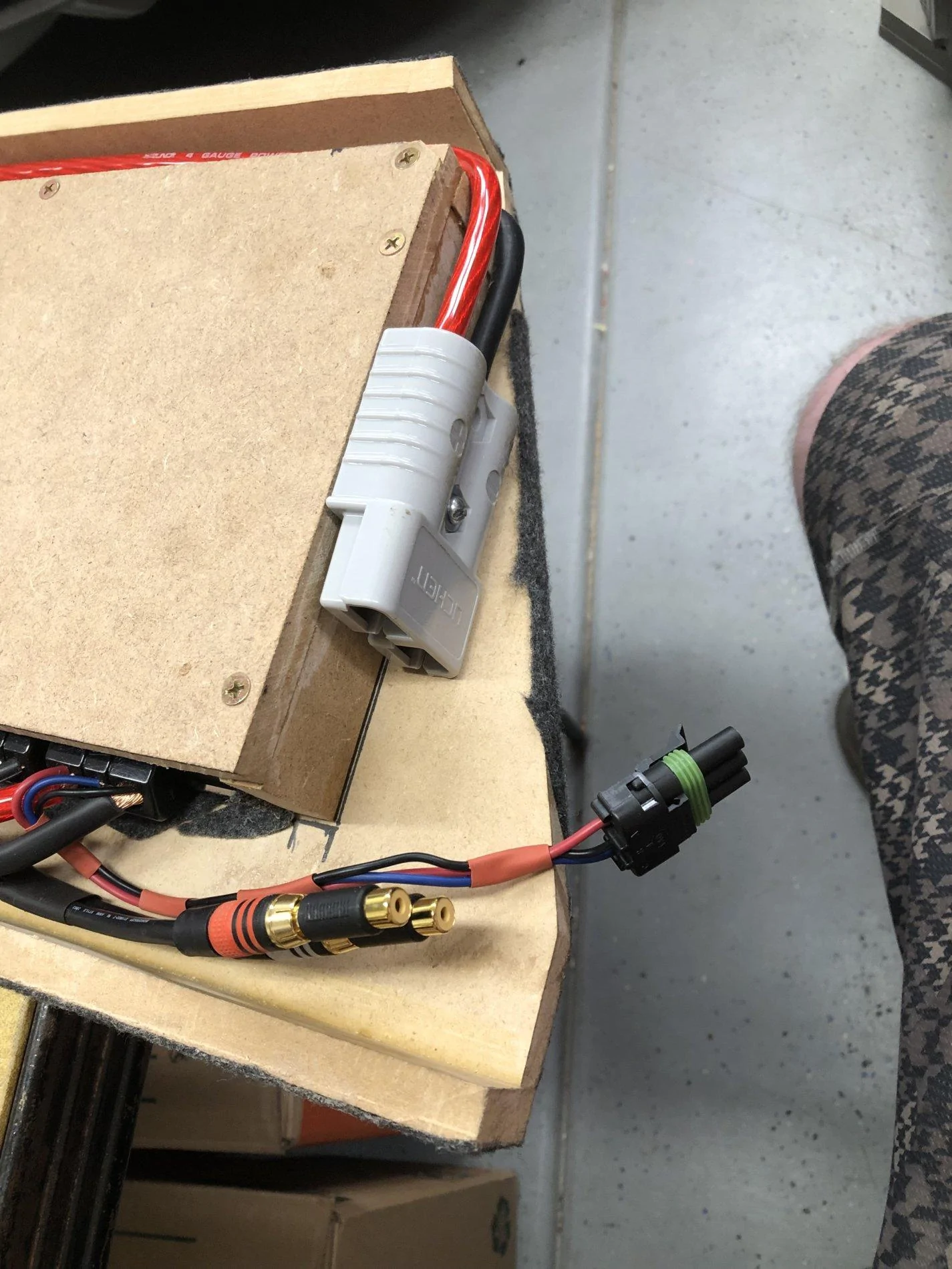
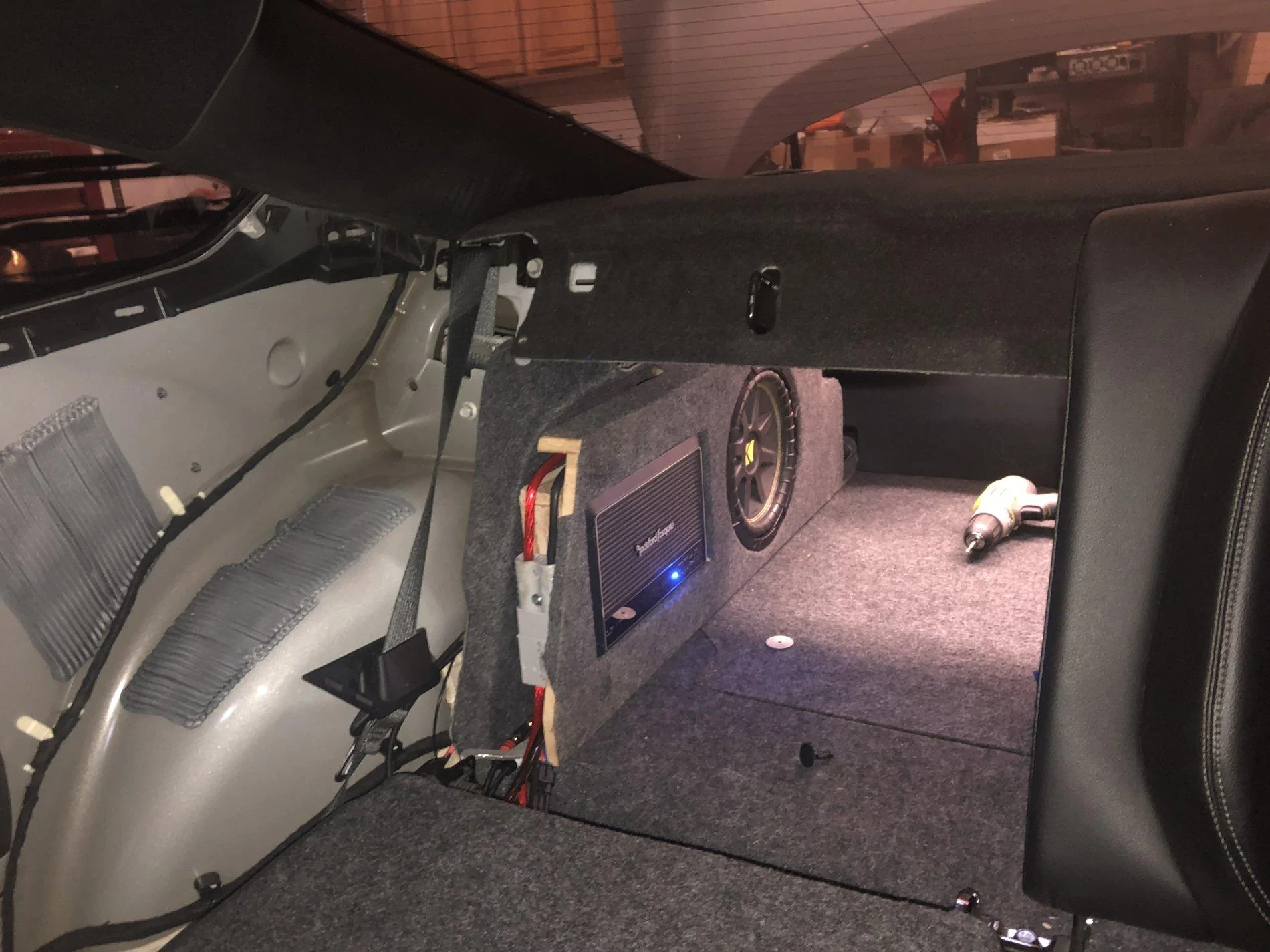
After this was complete, I mentioned that I wanted to make the box removable. So As I wired the box, I made it with connectors. An Anderson Connector for the power for the amp. A 3 pin connector that was the power for the line out converter and the amp on wire, and rca couplers. In this section you will see the wiring starting to take shape.
View attachment 343285
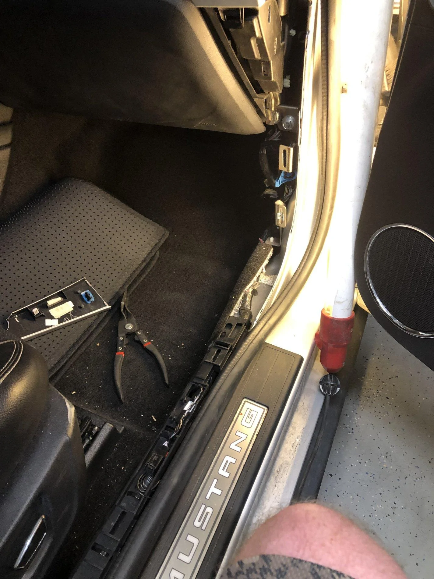
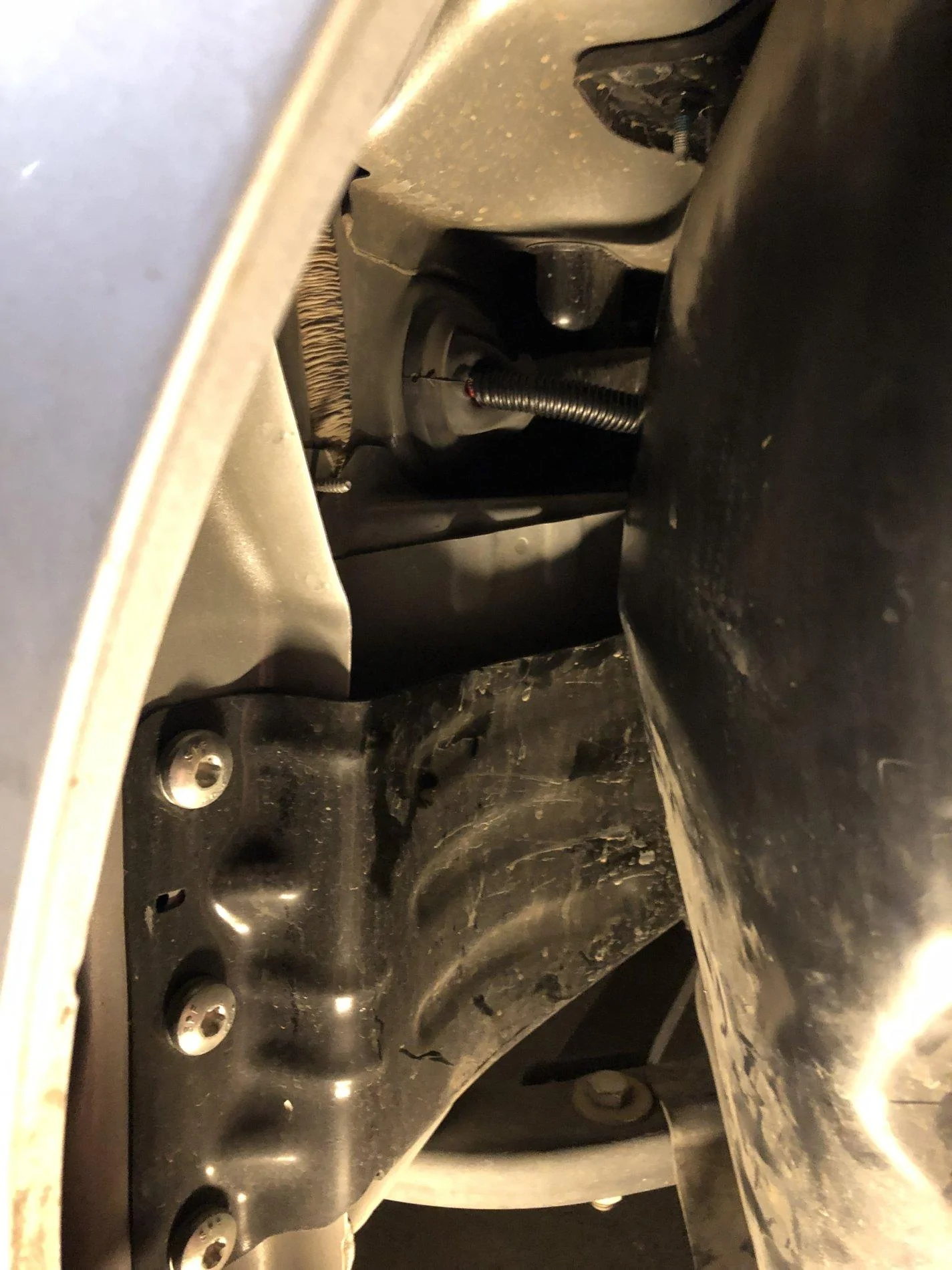
Next came wiring the car, I had watched youtube videos of people going up the passenger side of the car to run the power wires. Another video had shown a good section to connect the line out converter right where I was installing the box.
So once the material was put back in place you could not see the line out converter at all. I knew I did not want the box to move so I worked at making mounts for the box. On the front side I made a bracket that would wedge on the outside of the seat bracket. On the rear I made a bracket that would screw into the cargo net nut.
I was unhappy how the box sat at the rear, so I cut some material out of the rear of the box to where the bracket would be flush with the bottom and I carpeted it to match. As I was nervous about the subwoofer becoming damaged I made my first subwoofer grill from supplies from home depot, it was effectively a chicken mesh grill with a lexan carpetted surround. The chicken mesh would deform with the different frequencies that the amp produced. I knew this would be temporary.
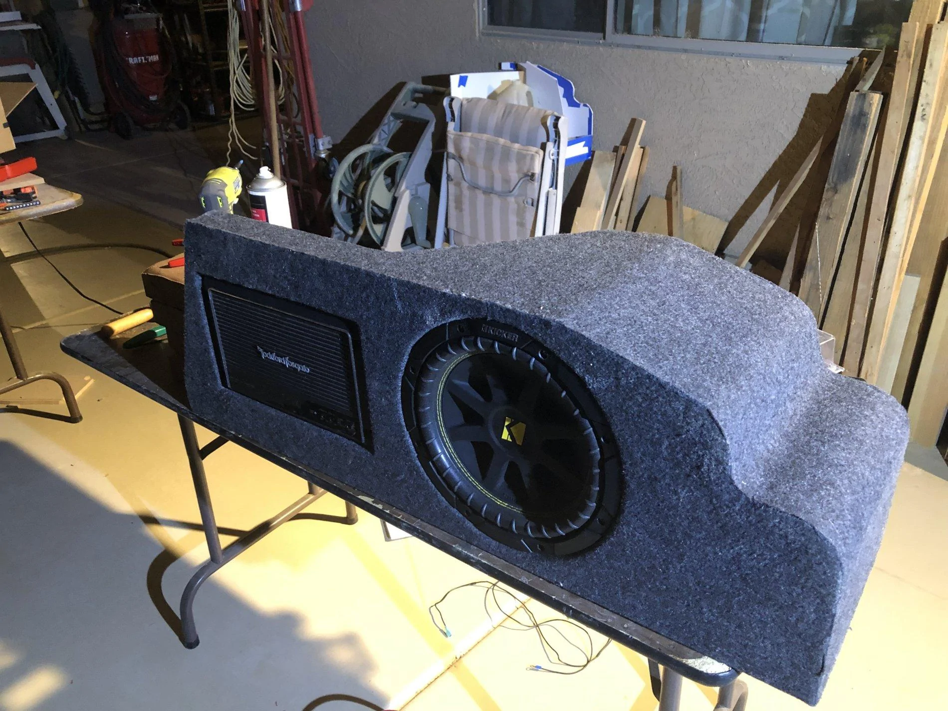
So I remade the grill from a much stronger material and reused the lexan surround.
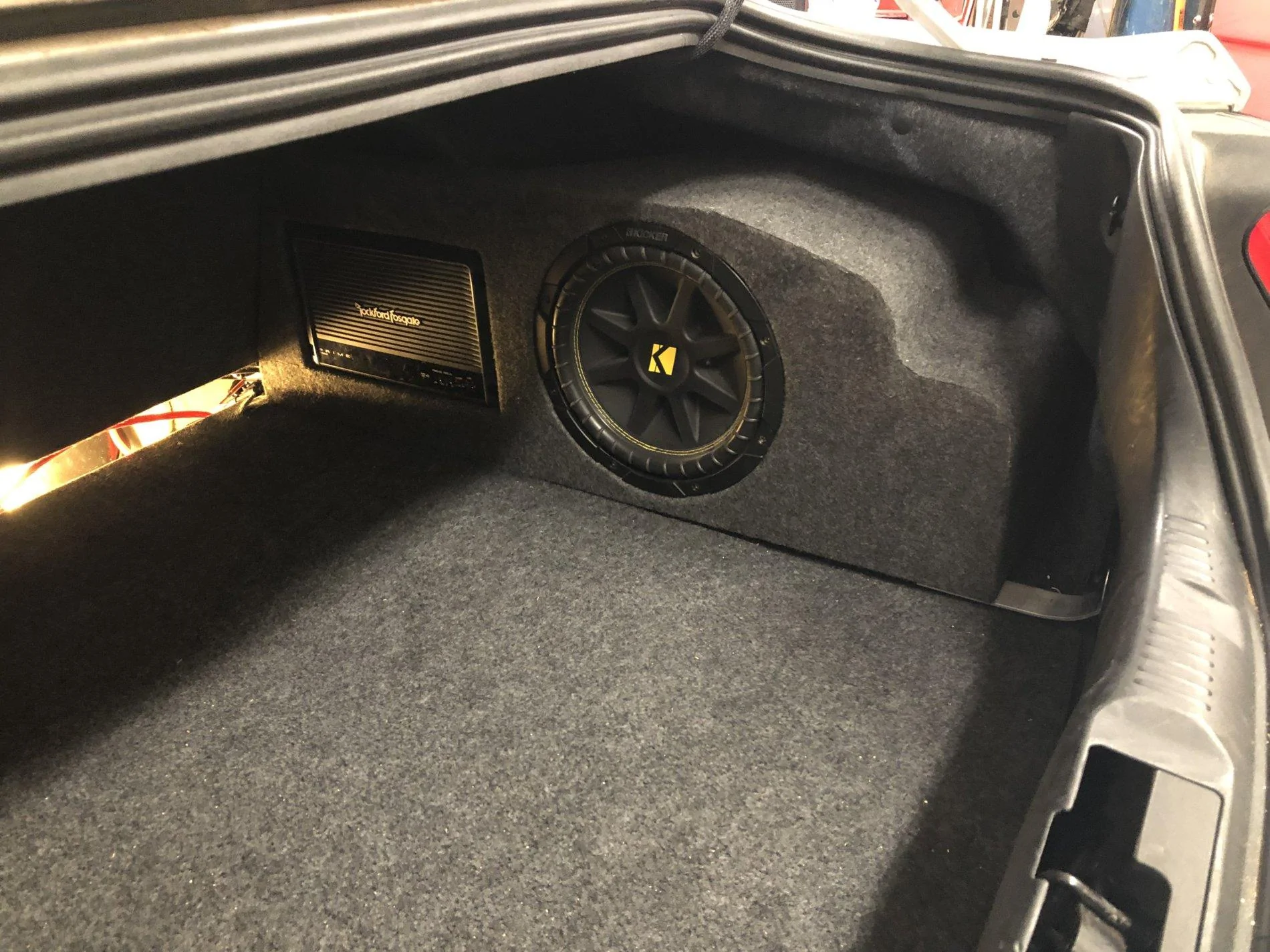
Finishing this project up, I upgraded to the next level up sub and cleaned up the wiring for much easier removal and installation.
Lastly not mentioned I ran my bass knob wiring through the dash and connected it underneath my steering wheel for easy adjustment and due to my car being an ecoboost deactivated the rear sound microphone that puts engine noise in the car.
Thanks for looking and enjoy!
Components I used were a Kicker Comp C 10, originally a rockford r150x2, replaced with a rockford r250x1, and the line out converter I used was a Skoche loc2sl
I first had a grand idea I would build it out of fiberglass, and when I started making it I misunderstood the instructions and did not put enough hardener. Which left me with a partially cured initial mold that was worthless. Upon my fathers advice I scrapped that project and decided to do it out of wood. Please enjoy the progress pictures.
In this photo I had laid out a flat section in which the amp would mount and the wiring could reside behind in the box.


After I laid the fiberglass it was evident I did not put enough hardener..
So I took my fathers advice and scrapped the project. I then used presentation board to start prototyping the wood box I would make.


The next challenge was that I was wanting to be able still do nice bends for a tight fit, so I researched something called kerfing. It is the cutting of wood in slices to where you can bend it into shapes. So I started practicing.

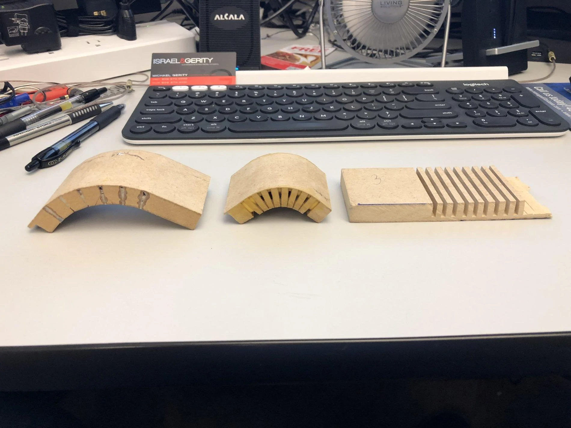
After I felt comfortable with this I started cutting out the actual box.


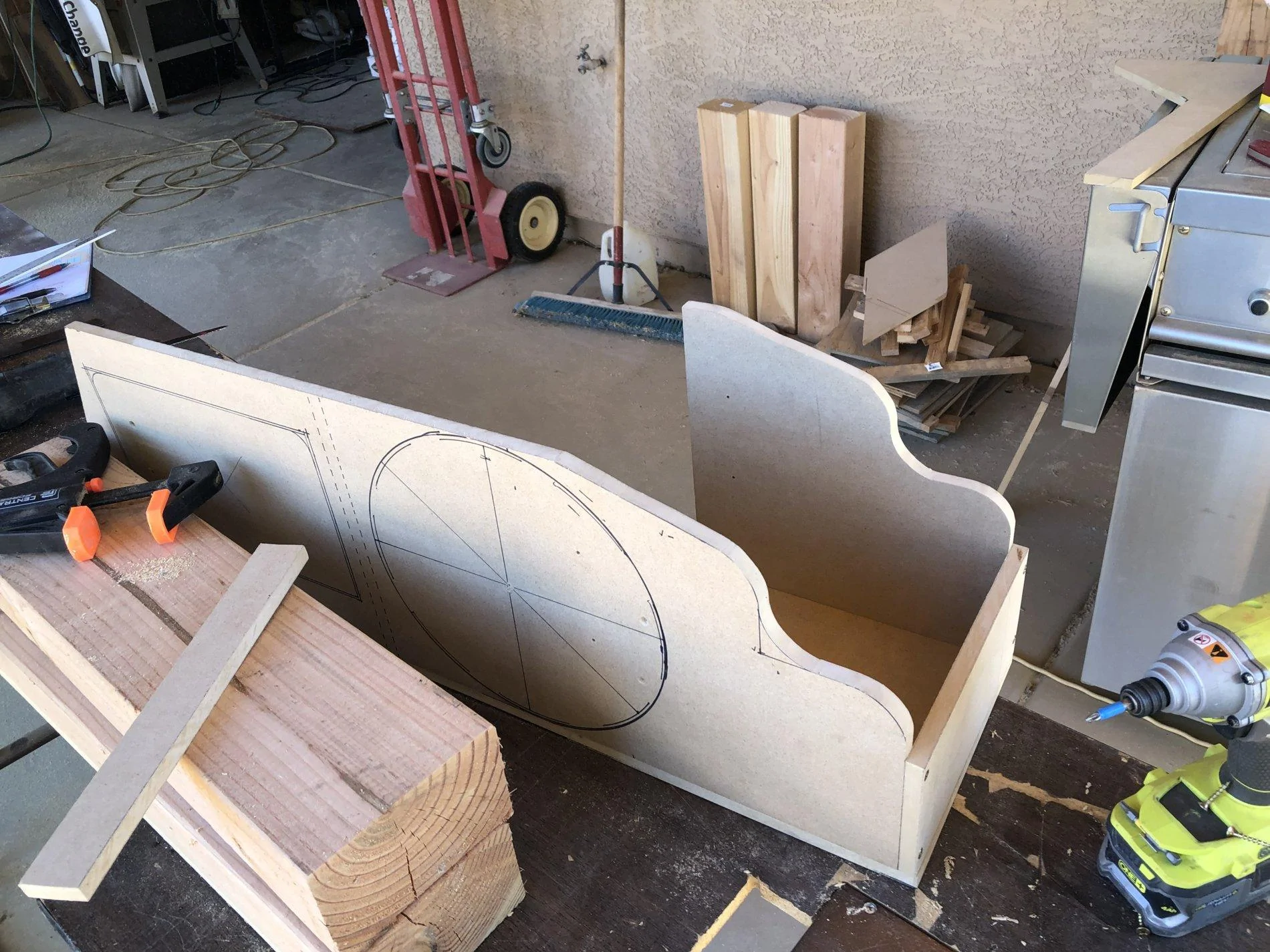

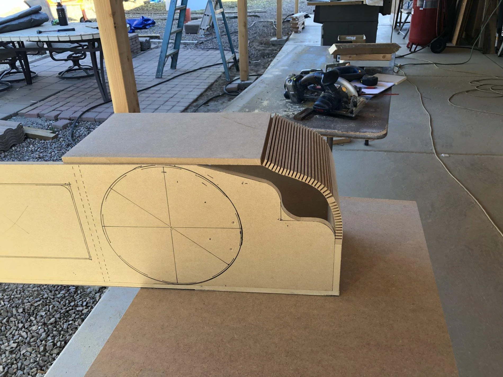

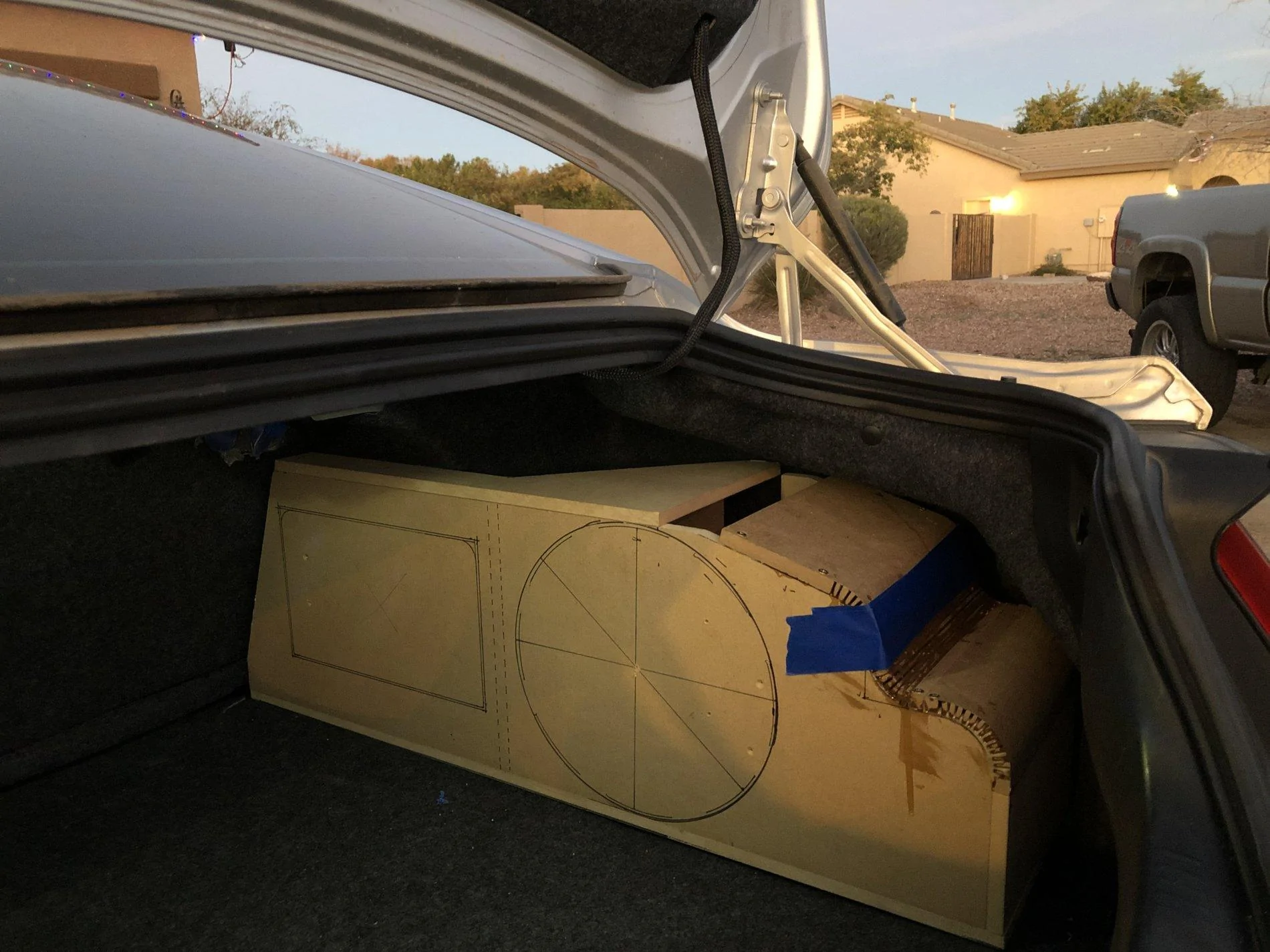

I knew I wanted the back section to fit nice and tight so I integrated kerf's into that as well.

As I got closer to finishing the box I finally started making the cavity for the amp.


Then came carpeting and making sure the box was sealed good.


After this was complete, I mentioned that I wanted to make the box removable. So As I wired the box, I made it with connectors. An Anderson Connector for the power for the amp. A 3 pin connector that was the power for the line out converter and the amp on wire, and rca couplers. In this section you will see the wiring starting to take shape.


Next came wiring the car, I had watched youtube videos of people going up the passenger side of the car to run the power wires. Another video had shown a good section to connect the line out converter right where I was installing the box.

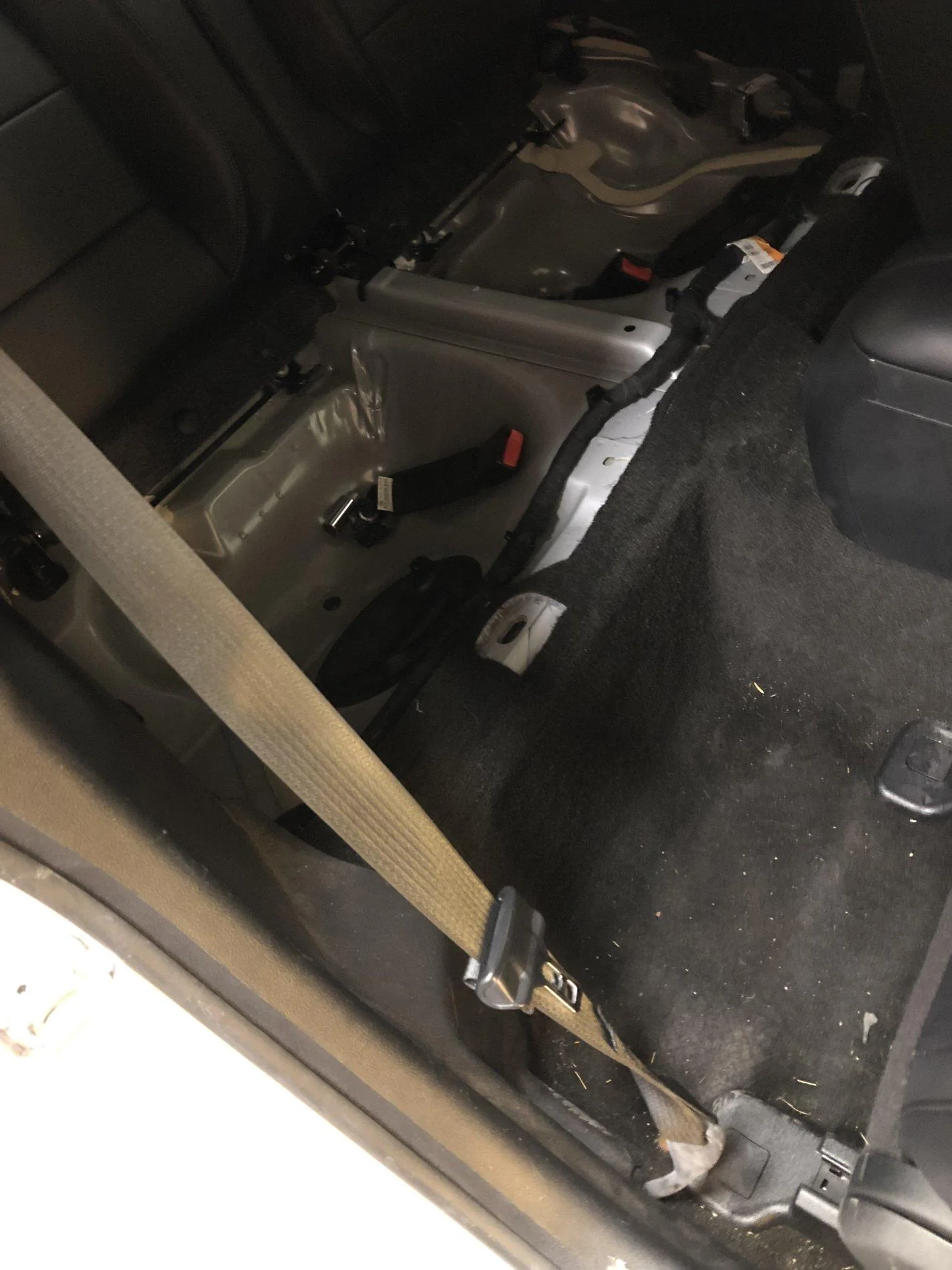

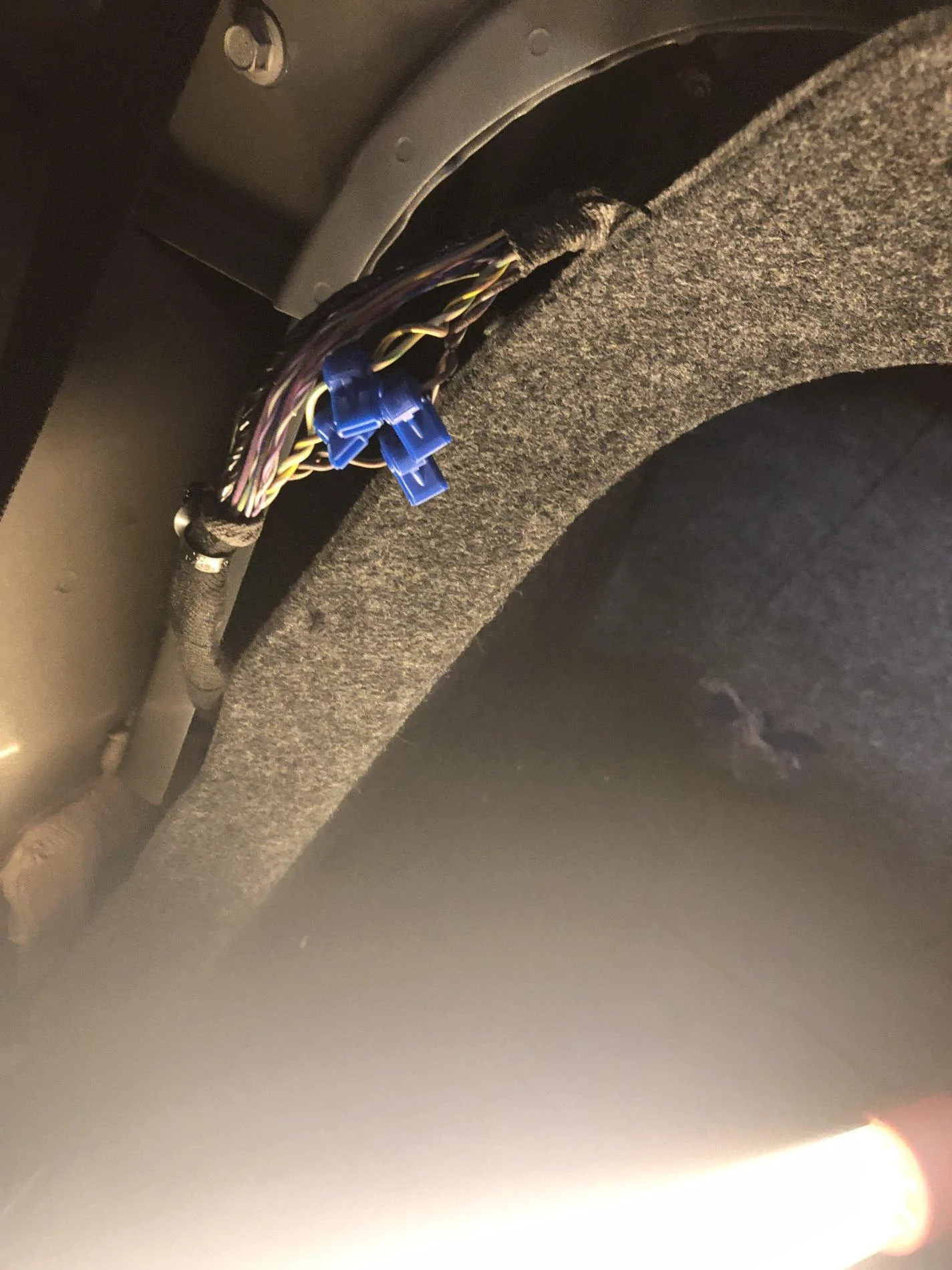
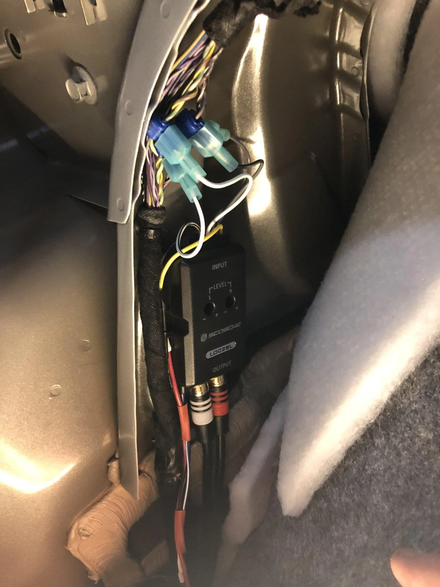
So once the material was put back in place you could not see the line out converter at all. I knew I did not want the box to move so I worked at making mounts for the box. On the front side I made a bracket that would wedge on the outside of the seat bracket. On the rear I made a bracket that would screw into the cargo net nut.


I was unhappy how the box sat at the rear, so I cut some material out of the rear of the box to where the bracket would be flush with the bottom and I carpeted it to match. As I was nervous about the subwoofer becoming damaged I made my first subwoofer grill from supplies from home depot, it was effectively a chicken mesh grill with a lexan carpetted surround. The chicken mesh would deform with the different frequencies that the amp produced. I knew this would be temporary.

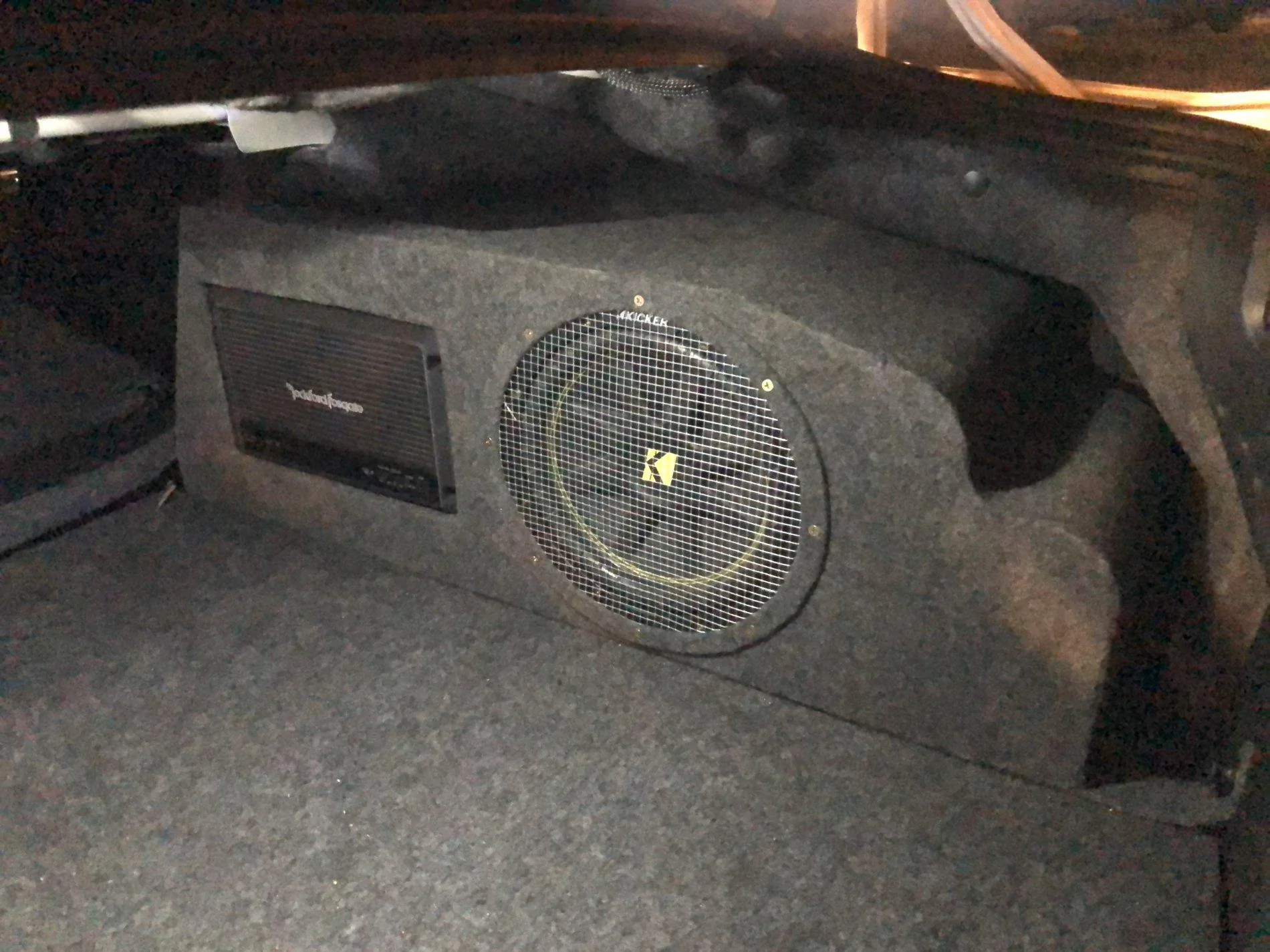
So I remade the grill from a much stronger material and reused the lexan surround.


Finishing this project up, I upgraded to the next level up sub and cleaned up the wiring for much easier removal and installation.

Lastly not mentioned I ran my bass knob wiring through the dash and connected it underneath my steering wheel for easy adjustment and due to my car being an ecoboost deactivated the rear sound microphone that puts engine noise in the car.

Thanks for looking and enjoy!
Sponsored
Attachments
-
0 bytes Views: 0
Last edited:
