Sponsored

Interactive Instrument Cluster Display

TheFreyFather

Member
Joined
Jun 11, 2020
Threads
3
Messages
10
Reaction score
6
Location
Little Rock
First Name
William
Vehicle(s)
2011 Triumph Speed Triple
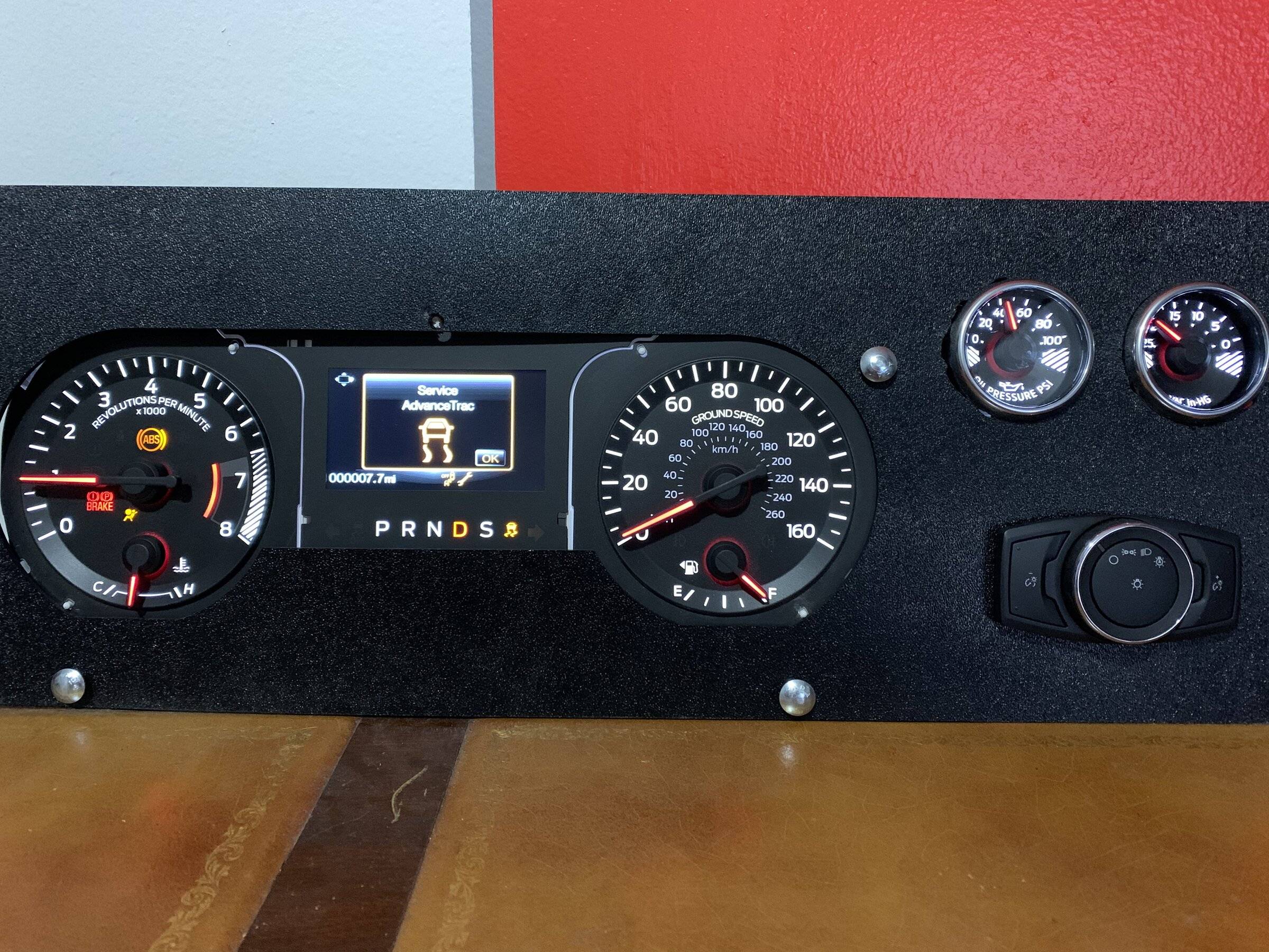
Check out this project I have been working on. It’s a 2015-2017 instrument cluster powered by an Arduino and CAN bus shield. I also have a set of performance pack gauges and functional headlight controller. I am using a few buttons and a switch to control reverse, neutral or drive, gas pedal, and ignition.

I have been doing a lot of reverse engineering of the CAN messages and programming to simulate the gauges working as they would in a real car.

Now I am just working on how to physically display the unit. This is my first try with a custom panel from SendCutSend.com. The measurements were rough so I had to make some adjustments to make everything fit.

I am pretty happy with it so far and wanted to show off my progress. All that is left is getting a good display set up for it, and finding a few more CAN messages.


DF8C1B45-BE05-4402-9DB8-2B1CAE5476BF.jpeg
Sponsored


KingKona

Well-Known Member
Joined
Jan 6, 2022
Threads
12
Messages
2,904
Reaction score
2,855
Location
Virginia
First Name
Shlomo
Vehicle(s)
2019 GT
Just a fun time project?
 

Rock50

Well-Known Member
Joined
Dec 24, 2018
Threads
5
Messages
140
Reaction score
156
Location
USA
Vehicle(s)
2021 Mach 1
Very cool and I am sure very time consuming.

Sort of a different subject question, but do you mind sharing what tools you used and where you connected for CAN bus sniffing? Some time ago, I tried to get what the exhaust toggle switch sends out. I was connecting at the OBD port pins for the various CAN speed networks with a basic Arduino sniffer. Was unsuccessful. Same for the steering wheel buttons. Almost like there is some firewall and these commands never reach the output at the OBD port.
 
OP
OP

TheFreyFather

Member
Joined
Jun 11, 2020
Threads
3
Messages
10
Reaction score
6
Location
Little Rock
First Name
William
Vehicle(s)
2011 Triumph Speed Triple
Very cool and I am sure very time consuming.

Sort of a different subject question, but do you mind sharing what tools you used and where you connected for CAN bus sniffing? Some time ago, I tried to get what the exhaust toggle switch sends out. I was connecting at the OBD port pins for the various CAN speed networks with a basic Arduino sniffer. Was unsuccessful. Same for the steering wheel buttons. Almost like there is some firewall and these commands never reach the output at the OBD port.
I’m glad you bring that up, I have been trying to figure out the steering wheel buttons myself.
I am using an Arduino Uno and a seeed studio CAN bus shield V2. With the seeed studio CAN library.
I actually don’t have a Mustang to log data from, but my plan was to go to a dealer and see if they would let me get plug into the OBD port but I assume that is going to be unlikely.
Initially I only had the cluster and couldn’t get it to respond. Eventually I reached out to someone on the forum and they suggested I buy a gateway module, which is the component that houses the OBD2 port and connects the 3 high speed buses. There is some kind of data translation at the gateway. You should still be able to read something from the OBD port - I’ve had success reading from the OBD port on other vehicles. My assumption is you will only read can data from one of the buses. Seems to me HS3 has the lowest priority devices on it, so thats not the one you would see on the OBD port. I think you would need to tie into the HS3 bus behind the dash to get a good reading on the valve message and steering wheel message.
I am currently feeding data through the OBD port with the cluster connected on HS3.
Sorry for the long response!
 

Sponsored

Rock50

Well-Known Member
Joined
Dec 24, 2018
Threads
5
Messages
140
Reaction score
156
Location
USA
Vehicle(s)
2021 Mach 1
The longer the reply the better.

So you started going the other route, you are stimulating signals.

This is what I originally posted, has some good info as to what I did and how far I got: https://www.mustang6g.com/forums/threads/exhaust-and-drive-mode-selection.138021/. Was basically able to see traffic on all buses at the OBD port, even had a little sketch that would filter out repeating commands that should have happened with same button presses, but it never worked for me. I started with the exhaust mode switch below the A/C controls, then switched to the steering wheel controls, as I found examples for other cars, but again, no go. Almost like the button press traffic was never reaching the OBD port. It is probably best to pull that entire switch panel out and connect to its bus output. But I ran out of steam and didn't feel like pulling the thing apart. My idea was to simulate presses and have the exhaust modes automatically change to whatever without having to cycle manually every time you start the car.

You seem to be more motivated then I am. Maybe some nice local member will give you access to a car and let you experiment. Although, you have to be a little careful, as there were a couple of times during my testing, where some of the modules went offline, likely protecting themselves from malformed data. Lucky me, disconnecting the car battery for a few minutes brought them back to life. Also had to clear a few communication failure related codes with Forscan.
 
OP
OP

TheFreyFather

Member
Joined
Jun 11, 2020
Threads
3
Messages
10
Reaction score
6
Location
Little Rock
First Name
William
Vehicle(s)
2011 Triumph Speed Triple
Thats a cool project. We should be able to figure this out.
One minor thing I noticed in your post, it looked like you were using 250kbps and 125kbps to read the HS buses, but those are actually at 500kbps. That would be worth trying again if it was a simple baud error.
If you do get a good log I would be happy to look through it and compare with the messages I have.
I wasn’t that concerned before about plugging into someone else’s car because I assumed just reading messages would be harmless. I figured the only damage would come from trying to send messages. But now that you say you had issues I am a little more hesitant…
I recall seeing a diagram of what modules are on each bus but can’t find it now. The IPC was on HS3 for sure, I’m wondering if the other modules we are talking about are on the same bus - the steering wheel module and whatever module handles the toggle switches below HVAC.
 
OP
OP

TheFreyFather

Member
Joined
Jun 11, 2020
Threads
3
Messages
10
Reaction score
6
Location
Little Rock
First Name
William
Vehicle(s)
2011 Triumph Speed Triple
It is probably best to pull that entire switch panel out and connect to its bus output.
Yes I agree that would be easiest in terms of decoding messages. It does seem like it would be a hassle to do physically. I assume the steering wheel module would be a lot easier to access than getting behind the toggle switch panel. That may be worth a shot to determine steering wheel button messages.
Sponsored


Top