Porcu5
New Member
- Joined
- May 15, 2018
- Threads
- 1
- Messages
- 1
- Reaction score
- 0
- Location
- California
- Vehicle(s)
- 2018 EcoBoost
- Thread starter
- #1
View attachment 166559
Hi, all
I need some electrical configuration/modification advise.
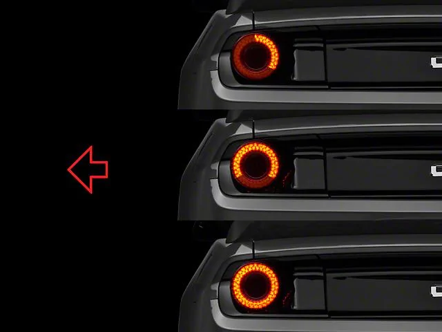
This is for Rear LED tail lamp project and try to use GT style lamp that I fond on online, I am thinking to build turn signal inside of this donuts shaped lamp, like R34 GTR inner lamp looking kind..
I am involved with project that I need to somehow convert US 2 way rear combination lamp configuration into JPN complying 3 way ( separate amber turn signal ) configuration. I also need to cancel sequential function as well..
Objective is
1. Cancel sequential turn signal function.
2. Need to isolate turn signal pules from brake function.
( I am making separate amber turn signal lamp)
3. I am hoping to achieve above 2 goal below rear body control module output(if possible)
= I prefer not to run to obtain front turn signal ,, best if I can achieve only at the down below rear body control module output.
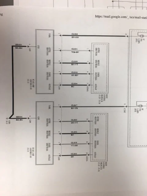
Looking at wiring diagram, for RH side, I see 3 lamp per side is individually fed by
Outer STOP/TURN(GY-VT)
Middle STOP/TURN(BN)
Inner STOP/TURN(VT-OG)
lines from rear body control module.
And combined GND
I also see wire called
OUTAGE(GN) wire goes into tail lamp.
I am terribly sorry, dealer gave me this extremely low resolution diagram..
Does anyone know if this OUTAGE line is +V signal to shut off to make turn signal blinking while brake lamp is ON?
I have not been able to research about if rear lamp is monitored or controlled via CAN communication, but I do not see CAN communication wires in diagram,,so I am hoping it is simple voltage ON OFF communication.
About sequential function
Will it be OK to combine OUTER MIDDLE INNER lamp wire into 1 bundle?
If I can, now this rear tail lamp is simple 2 way COMBINATION lamp configuration.
from here, I thought I can combine with some 2 way to 3 way converter, but some of converter I found had issue of when BRAKE is applied, turn signal output is flipped ON and OFF from front turn blinking timing
I think converter is primary cross trigger and feed combined brake line,
Another relay to switch pole to detect when brake is applied
Another relay powered by combination signal ON=not continue, OFF=continue to make isolated blinking possible.
But problem I found is that, when brake applied and also turn signal is used, front turn signal timing and rear signal timing is flipped = alternate.
Is there way to somehow utilize,,, at least blinking signal I obtained into proper blinking timing?
I am aware of if i run wire to extract front turn signal timing, or solid signal that indicate when turn signal use, I can make front and rear matching signaling..
But really hoping I can achieve this just by below rear body control module.
If anyone familiar with electrical configuration, or know product that make this achieved, please kindly advise me.
Thank you.


I need some electrical configuration/modification advise.
This is for Rear LED tail lamp project and try to use GT style lamp that I fond on online, I am thinking to build turn signal inside of this donuts shaped lamp, like R34 GTR inner lamp looking kind..
I am involved with project that I need to somehow convert US 2 way rear combination lamp configuration into JPN complying 3 way ( separate amber turn signal ) configuration. I also need to cancel sequential function as well..
Objective is
1. Cancel sequential turn signal function.
2. Need to isolate turn signal pules from brake function.
( I am making separate amber turn signal lamp)
3. I am hoping to achieve above 2 goal below rear body control module output(if possible)
= I prefer not to run to obtain front turn signal ,, best if I can achieve only at the down below rear body control module output.
Looking at wiring diagram, for RH side, I see 3 lamp per side is individually fed by
Outer STOP/TURN(GY-VT)
Middle STOP/TURN(BN)
Inner STOP/TURN(VT-OG)
lines from rear body control module.
And combined GND
I also see wire called
OUTAGE(GN) wire goes into tail lamp.
I am terribly sorry, dealer gave me this extremely low resolution diagram..
Does anyone know if this OUTAGE line is +V signal to shut off to make turn signal blinking while brake lamp is ON?
I have not been able to research about if rear lamp is monitored or controlled via CAN communication, but I do not see CAN communication wires in diagram,,so I am hoping it is simple voltage ON OFF communication.
About sequential function
Will it be OK to combine OUTER MIDDLE INNER lamp wire into 1 bundle?
If I can, now this rear tail lamp is simple 2 way COMBINATION lamp configuration.
from here, I thought I can combine with some 2 way to 3 way converter, but some of converter I found had issue of when BRAKE is applied, turn signal output is flipped ON and OFF from front turn blinking timing
I think converter is primary cross trigger and feed combined brake line,
Another relay to switch pole to detect when brake is applied
Another relay powered by combination signal ON=not continue, OFF=continue to make isolated blinking possible.
But problem I found is that, when brake applied and also turn signal is used, front turn signal timing and rear signal timing is flipped = alternate.
Is there way to somehow utilize,,, at least blinking signal I obtained into proper blinking timing?
I am aware of if i run wire to extract front turn signal timing, or solid signal that indicate when turn signal use, I can make front and rear matching signaling..
But really hoping I can achieve this just by below rear body control module.
If anyone familiar with electrical configuration, or know product that make this achieved, please kindly advise me.
Thank you.

Sponsored
Attachments
-
0 bytes Views: 0
Last edited: