Weeee
Well-Known Member
- Thread starter
- #1
I bought a B&O amplifier from a wrecked convertible Mustang to learn more about what its hardware could support. I took these photos through a magnifying glass, so you will notice distortion along the edges. The blue stuff is a thermal paste that makes contact with the case, which is a massive heat sync.
Kudos to @omiga for the assistance in analyzing the components.
What B&O states on their website about the amplifier:

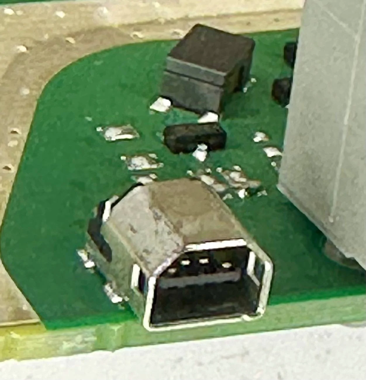
Undocumented USB port:

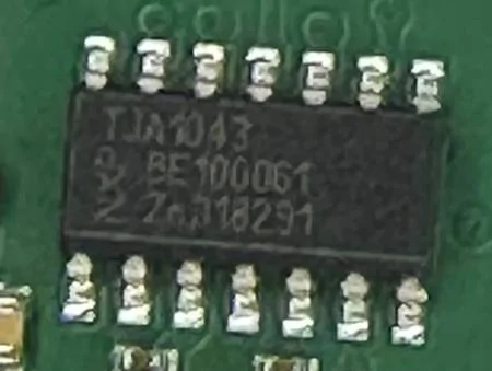
NXP TJA1043:

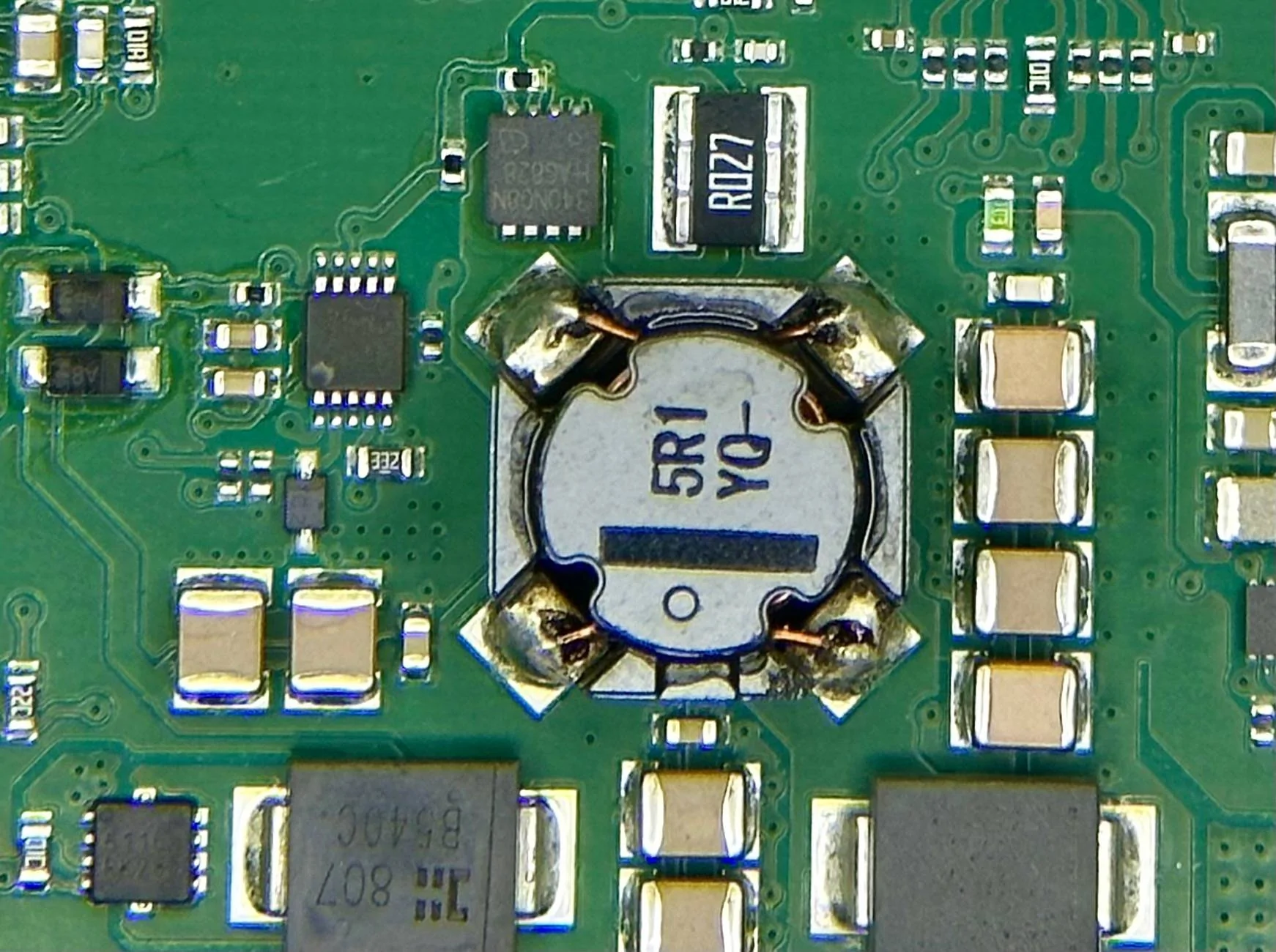
TI CDCE913:

Analog Devices ADAU1451:

Cirrus Logic CS5368-DQZ:

NEC 70F3580(A1):

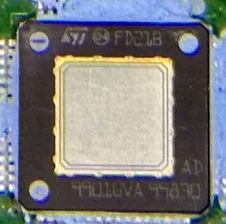
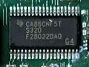
STMicroelectronics - FD21B:

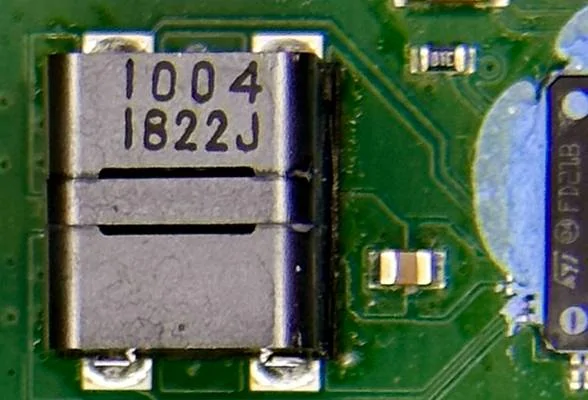
Butterworth filters:

Microcontroller - Link to the details

No clue what is going on here yet:

Kudos to @omiga for the assistance in analyzing the components.
What B&O states on their website about the amplifier:
- 900 Watts (Ford Media states it is 1000 Watts)
- 10 channel Analog Amplifier
- Digital Signal Processing (DSP)
- Speed Adaptive Volume
- Surround Sound
- Power Manager

Undocumented USB port:
- Assumed purpose - communication with the DSP chip.
- It appears to be a proprietary four-pin USB connection. It is present on every HARMON automotive amplifier I've reviewed.
- Do you know what this is or where to get the correct cable? Post up!

NXP TJA1043:
- Assumed purpose - Amp communication with the CAN bus.
- High-speed CAN transceiver interfaces between a Controller Area Network (CAN) protocol controller and the physical two-wire CAN bus.
- Link to the datasheet
TI CDCE913:
- Assumed purpose - Phase-locked loops (PLL) for the Analog Device DSP.
- I2C, Integrated EEPROM, Pin programmable, Spread-spectrum clocking (SSC).
- Link to the datasheet

Analog Devices ADAU1451:
- This is the digital signal processor (DSP) chip.
- There is plenty of vendor documentation, YouTube tutorials, and freely available software to tune this chip. I believe this chip is related to the undocumented USB port found on the board.
- Link to the datasheet

Cirrus Logic CS5368-DQZ:
- Assumed purpose - noise cancelling.
- 114 dB, 192 kHz, 8-Channel A/D Converter
- The empty slot makes me curious.
- Link to the datasheet

NEC 70F3580(A1):
- Assumed purpose - CAN bus

STMicroelectronics - FD21B:
- Assumed purpose - Class D amplifier chip.
- Unfortunately, the datasheet for this chip is unavailable. This suggests that it has been custom-made for HARMON Automotive. You can view the rest of their datasheets here if you'd like to get a rough idea of what they support.
- All five have the same part number.
- Each amplifier supports two channels.
Butterworth filters:
- Each channel of the amplifier has one.
Microcontroller - Link to the details
- Unknown purpose at this time.
No clue what is going on here yet:

Sponsored
Last edited:
")