TeamGomez
Well-Known Member
- Joined
- Apr 2, 2022
- Threads
- 23
- Messages
- 185
- Reaction score
- 332
- Location
- San Diego
- Website
- www.centripetalsolutions.com
- First Name
- John
- Vehicle(s)
- '18 350, 996 GT-3, E46 M3, SQ5, Tundra
- Thread starter
- #1
Just went through this and found some discrepancies that I read in various threads on the world wide web. I am powering a 500W amp so this works fine with a 4AWG power lead. Might be able to go one step larger gauge but this is ‘guaranteed’ (lol) for 4AWG cable.
First, I read that it wasn’t necessary to pull the fender liner because you can remove the battery tray and the firewall pass-thru is right there. It is not (at least on the 350). I pulled the battery box that is bolted to the tray and snapped one of the three bolts in the process due to liberal application of blue loc-tite at the Ford barn. It snapped about 1/4” down with good thread remaining so I simply re-used the snapped fastener given my bin of metric spares was light this particular size/thread pitch.

Battery tray removed….along with the ‘other half’ of the snapped fastener….
The fender liner must be pulled back to reveal the pass thru. I’m sure you could punch a new hole in the firewall beneath the battery tray with a 90 deg drill but there’s a nice nipple on the factory grommet just waiting to get pinched off.
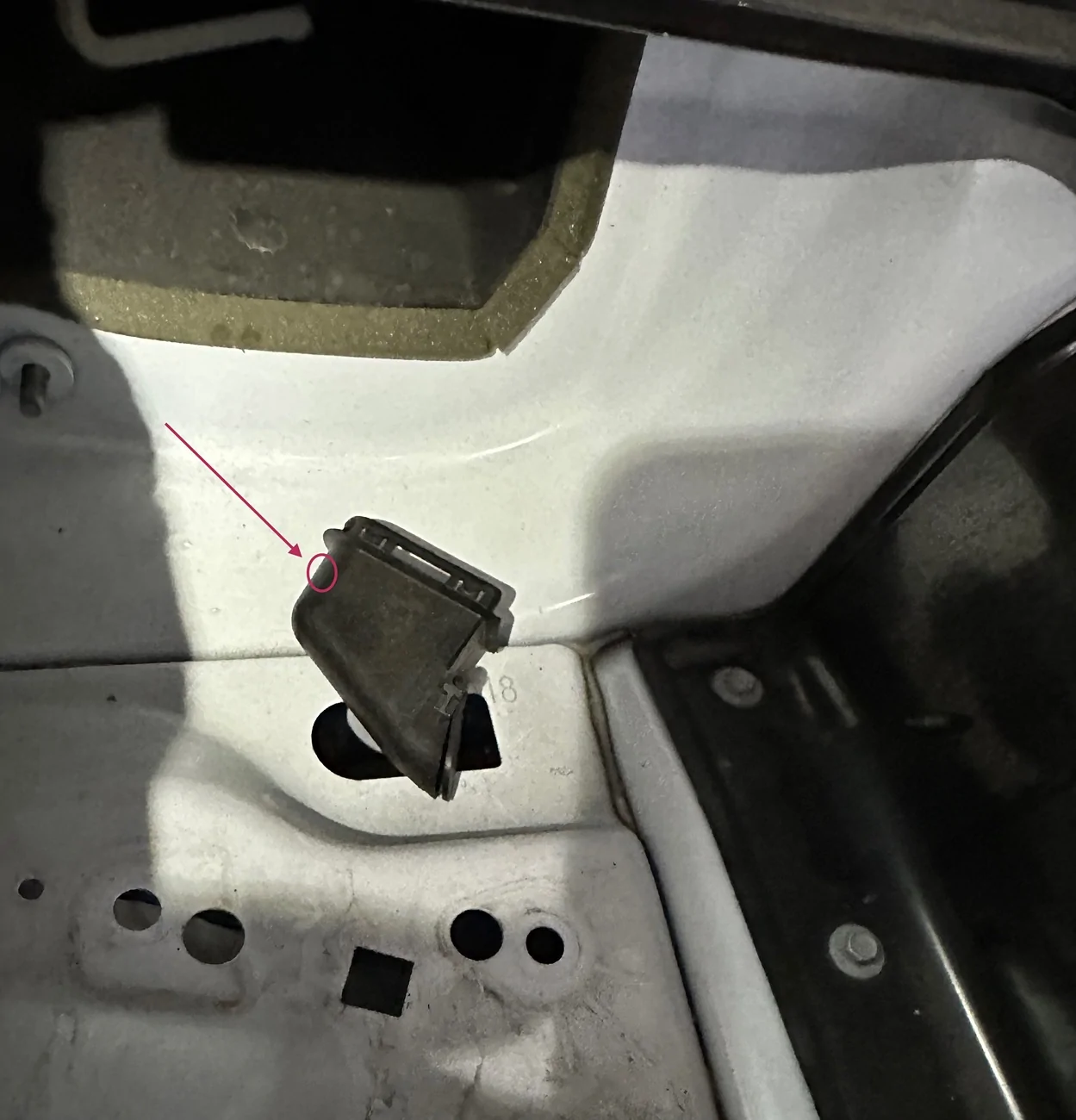
Our battery well (at least on the 2018) has a moisture capture drain with a flapper valve to let water out but keep it from intruding. I drilled a hole in this to pass the wire up and into the battery compartment from the wheel well. Hole was drilled at a 45 deg angle to provide sealing properties of the 4AWG sheath.

Battery well with the drain piece popped out (you have to remove it from the wheel well). Drilled hole at the circle.

Cable coming thru firewall and going up through the drain port
Cable coming into the battery well through the drain port.
Next is the attachment protocol. The battery clamps use force generated by two pieces sliding across one another at 45 deg and they are anodized. You should NOT simple bolt a power lead to the post beneath the clamping nut without first grinding/sanding/polishing/removing the anodized finish by a method of your choosing. I chose not to attach there because the factory post cover/shield can’t be used if you do. I chose to attach to the inboard side of the clamp and the ring terminal must be filed so it slides over the t-shaft that the clamping nut attaches to. You should also sand off the anodizing on this piece where the ring terminal rests and where it touches the clamp for best conductivity.
I punched a hole in the back of the battery box above the drain port about half way down to feed in the power cable. I cut the mounting plate off the fuse barrel and it rests nicely between the battery and the battery box.

Hope this helps the next installer get ‘er done quickly without any ‘design engineering’ adding unnecessary time to the project.
First, I read that it wasn’t necessary to pull the fender liner because you can remove the battery tray and the firewall pass-thru is right there. It is not (at least on the 350). I pulled the battery box that is bolted to the tray and snapped one of the three bolts in the process due to liberal application of blue loc-tite at the Ford barn. It snapped about 1/4” down with good thread remaining so I simply re-used the snapped fastener given my bin of metric spares was light this particular size/thread pitch.

Battery tray removed….along with the ‘other half’ of the snapped fastener….
The fender liner must be pulled back to reveal the pass thru. I’m sure you could punch a new hole in the firewall beneath the battery tray with a 90 deg drill but there’s a nice nipple on the factory grommet just waiting to get pinched off.
Our battery well (at least on the 2018) has a moisture capture drain with a flapper valve to let water out but keep it from intruding. I drilled a hole in this to pass the wire up and into the battery compartment from the wheel well. Hole was drilled at a 45 deg angle to provide sealing properties of the 4AWG sheath.
Battery well with the drain piece popped out (you have to remove it from the wheel well). Drilled hole at the circle.

Cable coming thru firewall and going up through the drain port

Cable coming into the battery well through the drain port.
Next is the attachment protocol. The battery clamps use force generated by two pieces sliding across one another at 45 deg and they are anodized. You should NOT simple bolt a power lead to the post beneath the clamping nut without first grinding/sanding/polishing/removing the anodized finish by a method of your choosing. I chose not to attach there because the factory post cover/shield can’t be used if you do. I chose to attach to the inboard side of the clamp and the ring terminal must be filed so it slides over the t-shaft that the clamping nut attaches to. You should also sand off the anodizing on this piece where the ring terminal rests and where it touches the clamp for best conductivity.

I punched a hole in the back of the battery box above the drain port about half way down to feed in the power cable. I cut the mounting plate off the fuse barrel and it rests nicely between the battery and the battery box.

Hope this helps the next installer get ‘er done quickly without any ‘design engineering’ adding unnecessary time to the project.
Sponsored
Last edited: