eisenhauer01
Well-Known Member
- Joined
- Apr 1, 2019
- Threads
- 22
- Messages
- 226
- Reaction score
- 256
- Location
- Walkertown, NC
- First Name
- Kenny
- Vehicle(s)
- 2015 Mustang GT
- Thread starter
- #1
As I am wrapping up my build, and began tuning / datalogging with Wengerd I decided to install a fuel pressure gauge for numerous reasons.
The car is a 2015 Mustang GT Performance Pack.
As the car did not come with any fuel pressure gauge, I began some research into how I wanted to go about this.
Currently the car has a factory fuel system, with a BAP.
For now, I did not want to change the fuel rails, so I found this little gem from Nitrous Outlet (00-01812) for around $60.

With the 1/8 NPT threaded hole, I was able to move forward.
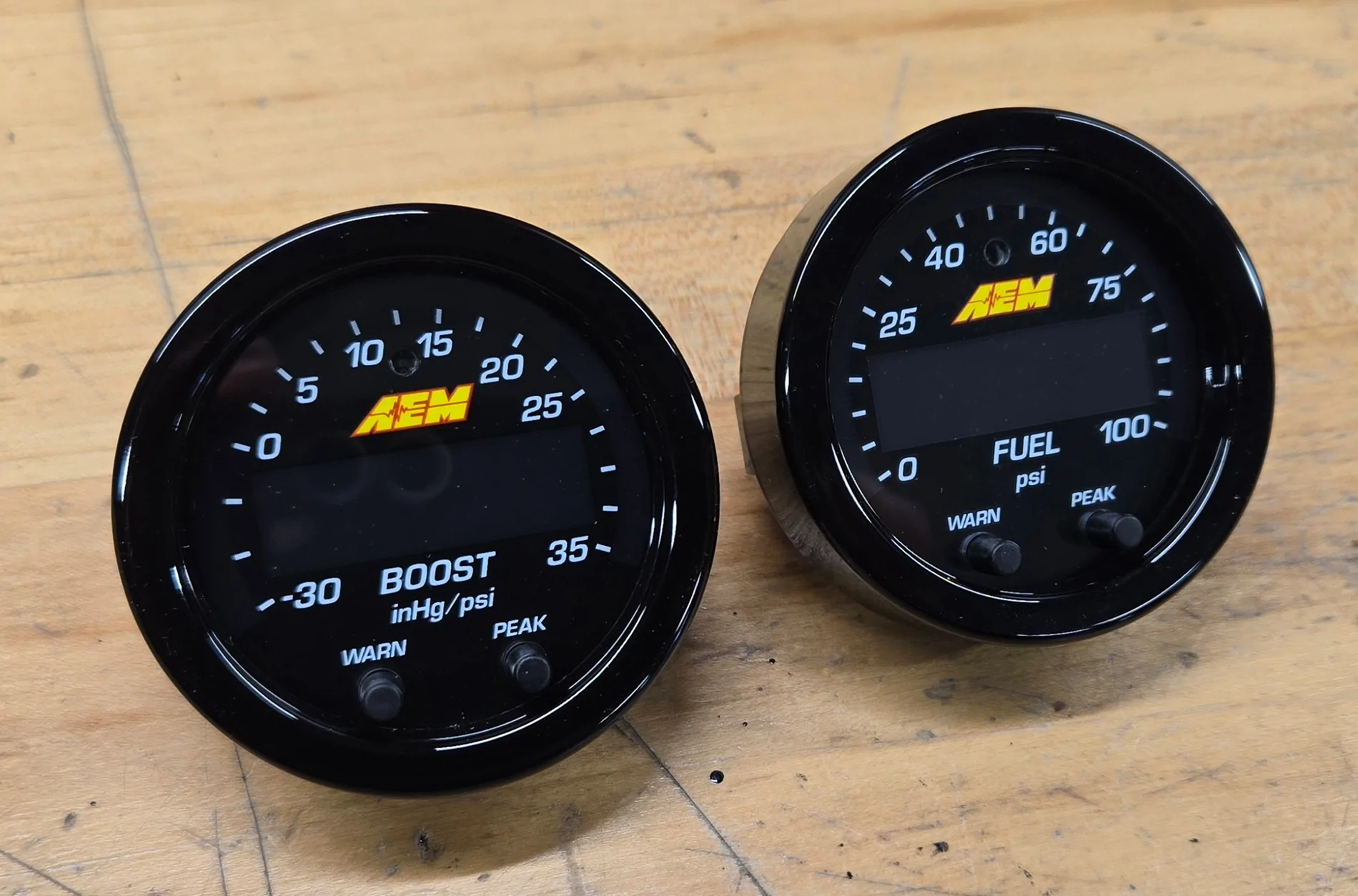
I decided on the AEW X-Series Gauge 30-0301 and I picked up the bezel kit for it, so I could change the face to black.
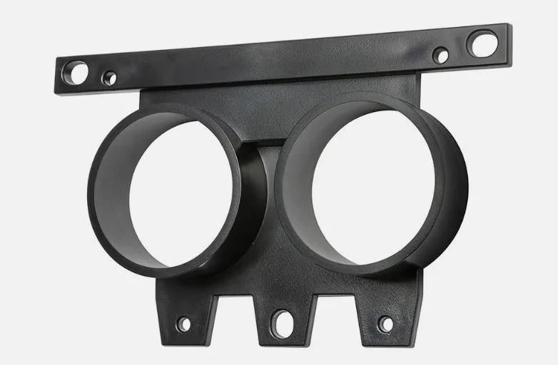
GlowShift makes a bracket that you can use to replace the factory PP gauges.
I looked at a few other similar brackets, but most were 3d printed.
While I love 3d printed stuff, if there is a plastic injection molded version of it, that is what I will pick for sure.
Both the Oil Pressure & Vacuum data are available in my digital dash, so out came the factory gauges.

That left me to figure out what to put in the other hole.
As the car already has a factory wideband, I decided to keep it simple and just install an actual boost gauge (not inferred data).
I purchased the AEW X-Series Boost Gauge 30-0306.
Here they are:

Before physically installing the gauges into the dash, I needed to get install the sensors and do the wiring.
So installing the sensors was pretty straight-forward.
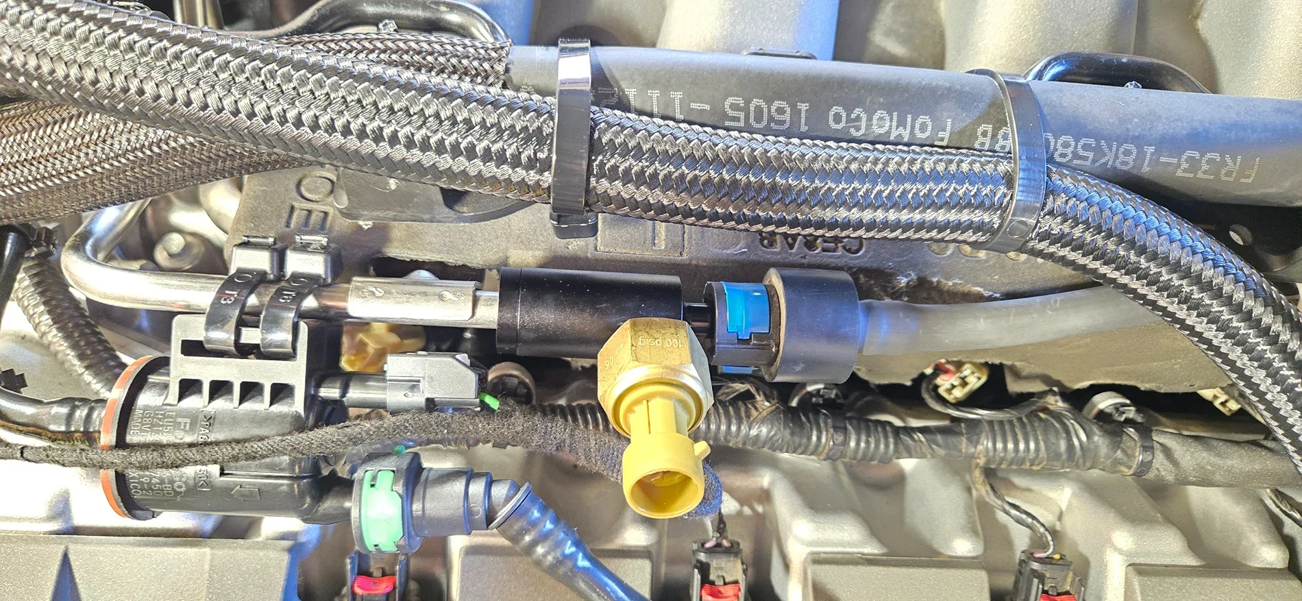
The Nitrous Outlet adapter made things easy with the Fuel Pressure Sensor.

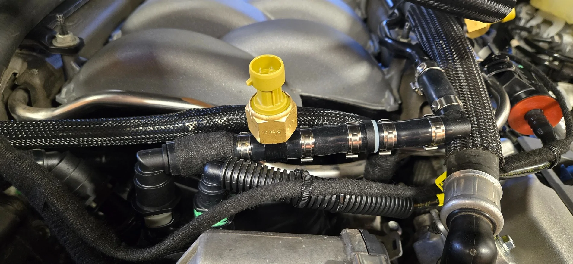
Then the vacuum / boost reference.
The silicone vacuum hose was barely touching the evap line connector, so I wrapped it in a little bit of tesa tape.
Then I began working on wiring.
The gauge harness has a few main items:
- Power / Ground
- Signal from Sensor
- Analog 0-5v Output
From AEM, they have the Power / Ground and the Analog 0-5v Output together inside of one insulation.
That was not going to work for me. The Power / Ground needed to go to one side of the car, and the Analog Output needed to go to the other.
I will explain more below.
Point is, I removed the insulation from that part of the harness, and separated the two pairs of wires.
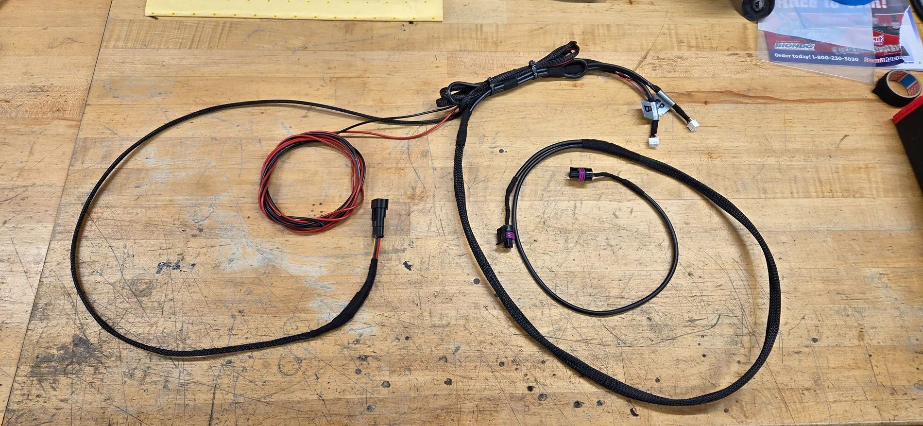
After some measuring (distance between sensors) and some test fitting, I went ahead and cleaned the harness up with looming material and tesa tape.
The white connectors in the upper right are what feed into the gauges.
The black connectors with the purple seals are for connecting to the sensors.
The red & black wires looped in a circle are the power / ground.
The last single connector is the 0-5v Analog Output.
One of the main reasons (besides monitoring it myself) for doing this install, was for Wengerd to be able to see these pieces of data as well.
That is where the Analog Output comes into play.
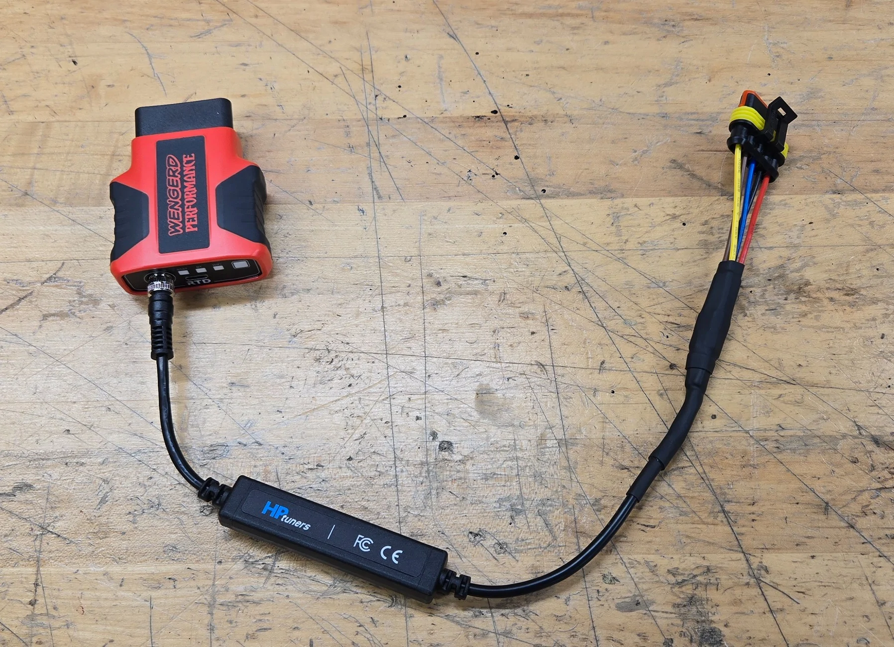
I purchased a HP Tuners ProLink+ Harness that works with my RTD4.
This harness plugs into my RTD4, and will accept two 0-5v Analog Inputs.
I wanted a clean install that would be easy to connect / disconnect, as the RTD4 is only in the car for tuning / datalogging purposes.
So this is what I came up with:

It plugs right into the connector that I wired into the AEM harness.
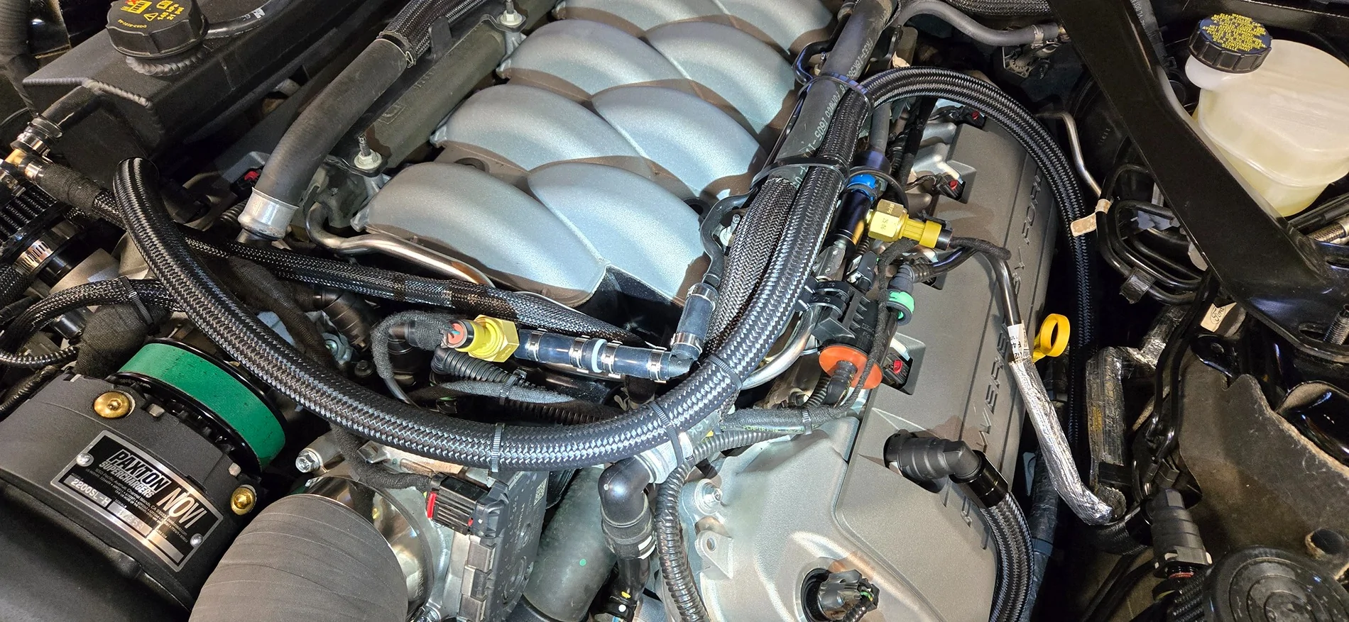
I removed the accelerator pedal, purchased a grommet that fit in the sound tube hole and put a slit into it, and ran the sensor side of the harness into the engine bay via the sound tube hole. Cleaned everything up.
After the harness was connected to the sensors, I began working on Power / Ground.
No pics, but I picked up a ground from right beside the glove box on the right hand side. 8mm screw for factory grounds.
Power was picked up off of Fuse 36 via a fuse tap.
It is the 2nd one down from the top, on the right hand side. 15A.
It is key on power.
With the wiring part of it completely done, it was time for the fun part.
Installing the actual gauges!
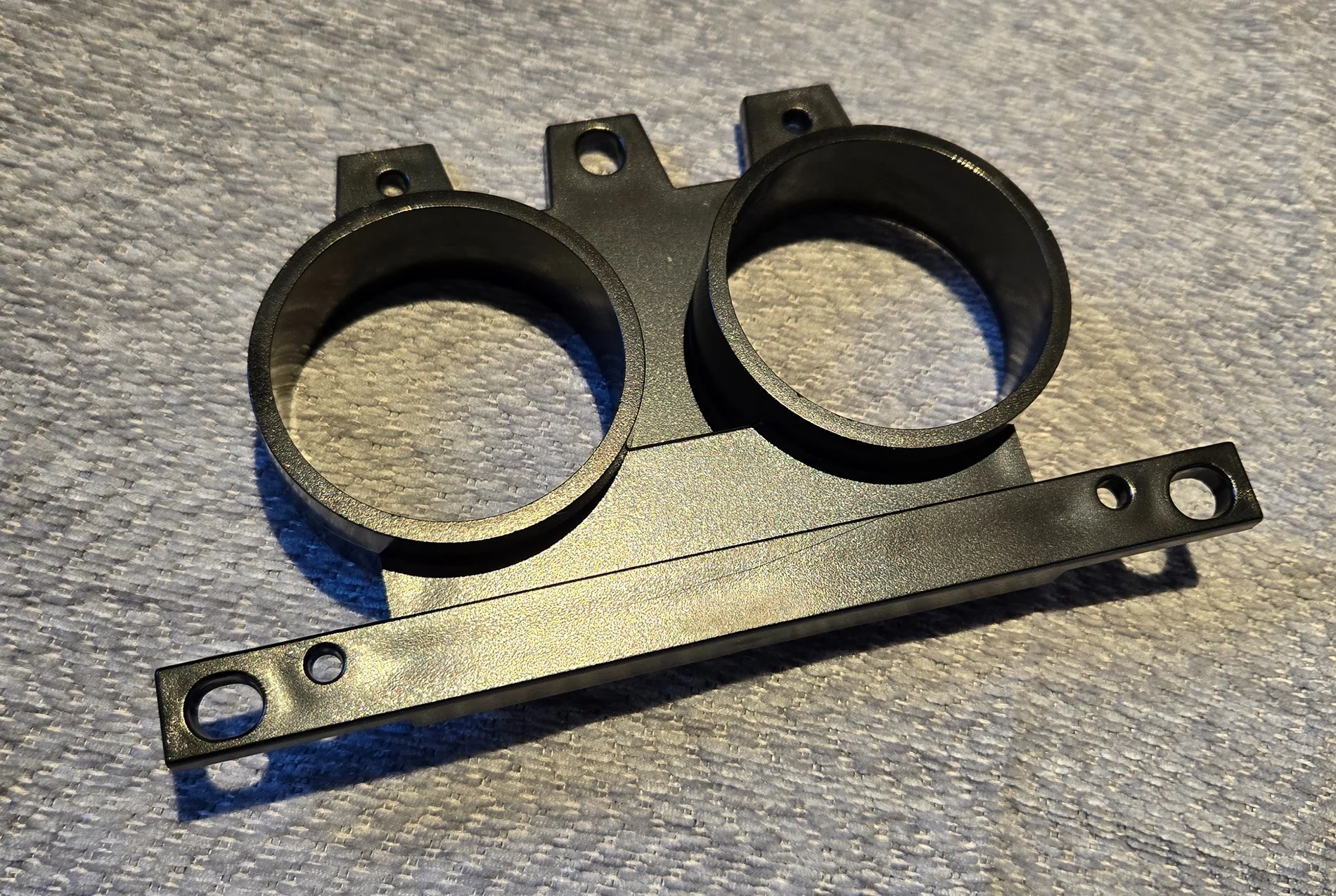
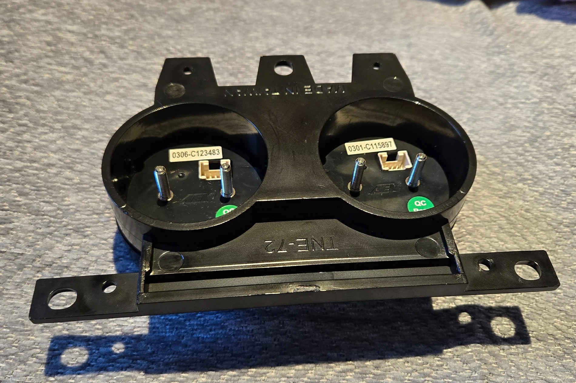
So upon looking at things closer, I realize that these AEM X-Series Gauges are very low profile.
The GlowShift bracket was much deeper than the stock AEW mounting system would allow


The gauges I believe were originally designed to be mounted into something thin. Similar to sheet metal or a flat dash material of some sort.
So I did some reverse engineering off of the bracket and gauges, and designed up a part to overcome this

A few hours later it was 3D printed, and worked out perfectly!


I installed the bracket into the dash trim, then installed the gauges.


Got things plugged up, and finished the install


Connected the RTD4 to the car, and connected the Analog Output Connector to the RTD4.
Tested things in HP Tuners VCM Scanner after setting up the two new channels, and things worked great.
Emailed Wengerd, told him which channels to add and how to Transform them, and we were all set.
Did an Idle log for him to verify he was seeing both channels with correct data, which he confirmed.
Now if only we could get some warm weather so I can go do some logging to finish this thing up!
The car is a 2015 Mustang GT Performance Pack.
As the car did not come with any fuel pressure gauge, I began some research into how I wanted to go about this.
Currently the car has a factory fuel system, with a BAP.
For now, I did not want to change the fuel rails, so I found this little gem from Nitrous Outlet (00-01812) for around $60.
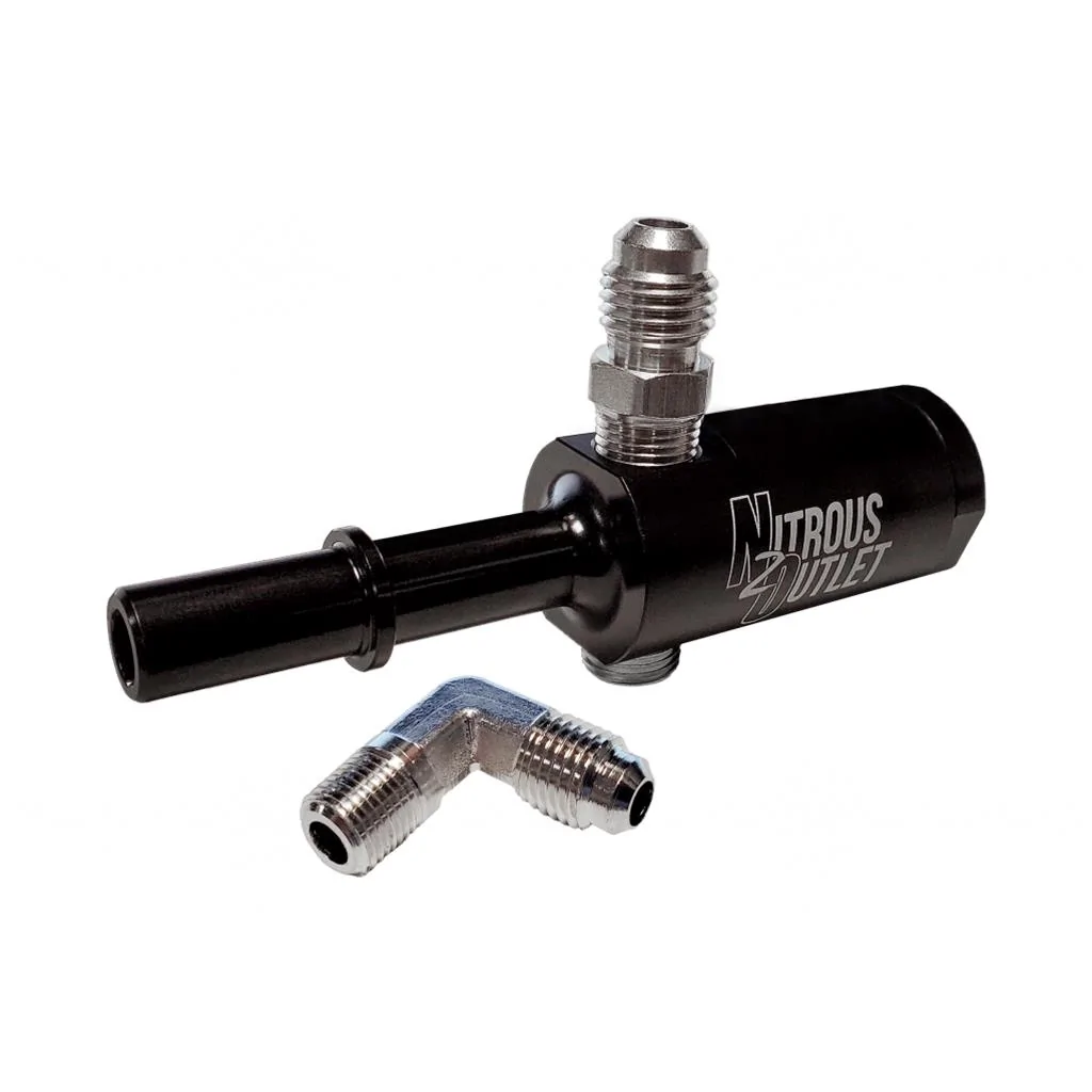
With the 1/8 NPT threaded hole, I was able to move forward.
I decided on the AEW X-Series Gauge 30-0301 and I picked up the bezel kit for it, so I could change the face to black.
GlowShift makes a bracket that you can use to replace the factory PP gauges.
I looked at a few other similar brackets, but most were 3d printed.
While I love 3d printed stuff, if there is a plastic injection molded version of it, that is what I will pick for sure.
Both the Oil Pressure & Vacuum data are available in my digital dash, so out came the factory gauges.
That left me to figure out what to put in the other hole.
As the car already has a factory wideband, I decided to keep it simple and just install an actual boost gauge (not inferred data).
I purchased the AEW X-Series Boost Gauge 30-0306.
Here they are:
Before physically installing the gauges into the dash, I needed to get install the sensors and do the wiring.
So installing the sensors was pretty straight-forward.
The Nitrous Outlet adapter made things easy with the Fuel Pressure Sensor.
Then the vacuum / boost reference.
The silicone vacuum hose was barely touching the evap line connector, so I wrapped it in a little bit of tesa tape.
Then I began working on wiring.
The gauge harness has a few main items:
- Power / Ground
- Signal from Sensor
- Analog 0-5v Output
From AEM, they have the Power / Ground and the Analog 0-5v Output together inside of one insulation.
That was not going to work for me. The Power / Ground needed to go to one side of the car, and the Analog Output needed to go to the other.
I will explain more below.
Point is, I removed the insulation from that part of the harness, and separated the two pairs of wires.
After some measuring (distance between sensors) and some test fitting, I went ahead and cleaned the harness up with looming material and tesa tape.
The white connectors in the upper right are what feed into the gauges.
The black connectors with the purple seals are for connecting to the sensors.
The red & black wires looped in a circle are the power / ground.
The last single connector is the 0-5v Analog Output.
One of the main reasons (besides monitoring it myself) for doing this install, was for Wengerd to be able to see these pieces of data as well.
That is where the Analog Output comes into play.
I purchased a HP Tuners ProLink+ Harness that works with my RTD4.
This harness plugs into my RTD4, and will accept two 0-5v Analog Inputs.
I wanted a clean install that would be easy to connect / disconnect, as the RTD4 is only in the car for tuning / datalogging purposes.
So this is what I came up with:
It plugs right into the connector that I wired into the AEM harness.
I removed the accelerator pedal, purchased a grommet that fit in the sound tube hole and put a slit into it, and ran the sensor side of the harness into the engine bay via the sound tube hole. Cleaned everything up.
After the harness was connected to the sensors, I began working on Power / Ground.
No pics, but I picked up a ground from right beside the glove box on the right hand side. 8mm screw for factory grounds.
Power was picked up off of Fuse 36 via a fuse tap.
It is the 2nd one down from the top, on the right hand side. 15A.
It is key on power.
With the wiring part of it completely done, it was time for the fun part.
Installing the actual gauges!
So upon looking at things closer, I realize that these AEM X-Series Gauges are very low profile.
The GlowShift bracket was much deeper than the stock AEW mounting system would allow
The gauges I believe were originally designed to be mounted into something thin. Similar to sheet metal or a flat dash material of some sort.
So I did some reverse engineering off of the bracket and gauges, and designed up a part to overcome this
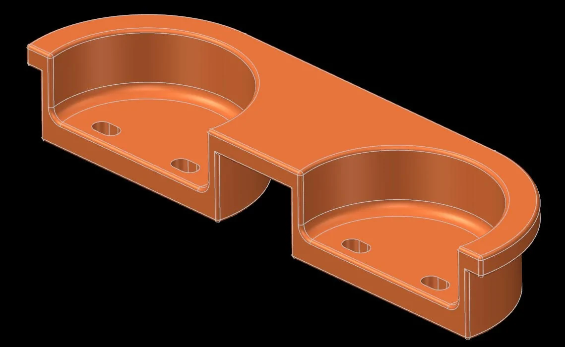
A few hours later it was 3D printed, and worked out perfectly!
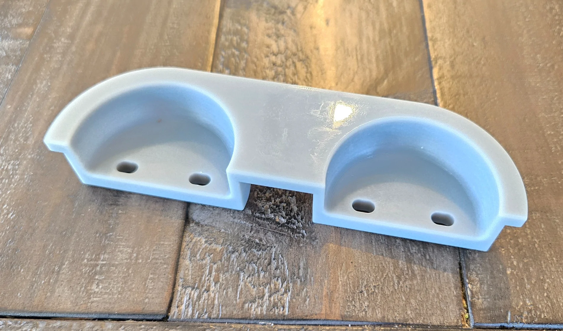
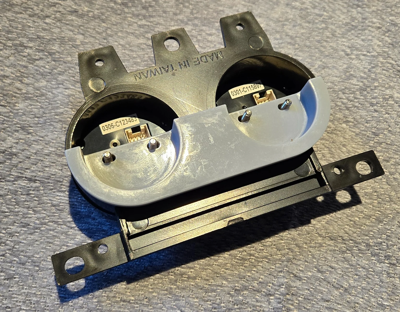
I installed the bracket into the dash trim, then installed the gauges.
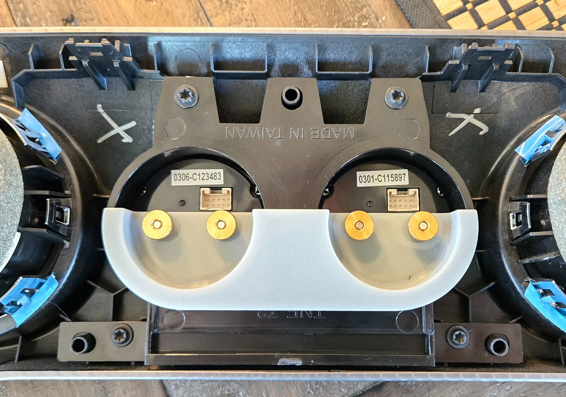
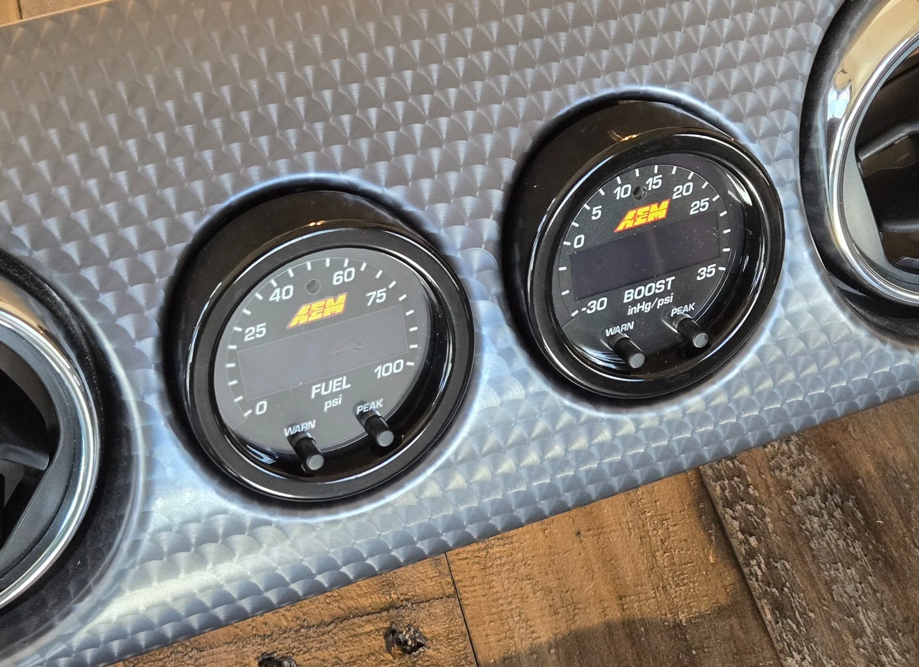
Got things plugged up, and finished the install
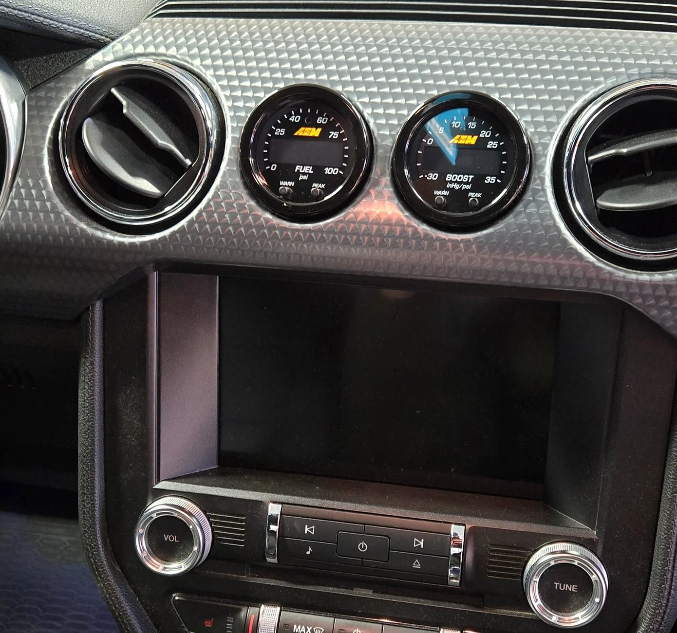
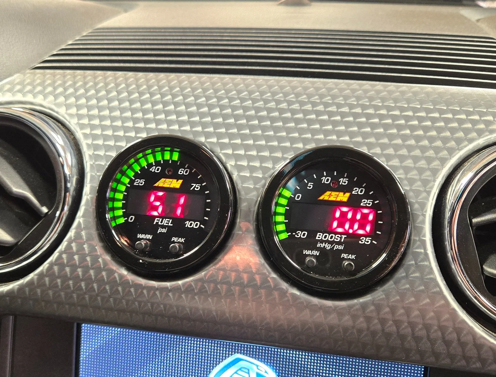
Connected the RTD4 to the car, and connected the Analog Output Connector to the RTD4.
Tested things in HP Tuners VCM Scanner after setting up the two new channels, and things worked great.
Emailed Wengerd, told him which channels to add and how to Transform them, and we were all set.
Did an Idle log for him to verify he was seeing both channels with correct data, which he confirmed.
Now if only we could get some warm weather so I can go do some logging to finish this thing up!
Sponsored