Bull Run
Well-Known Member
- Thread starter
- #1
I just upgraded from AEM V2 to Snow Stage 3 DI. AEM V2 worked fine but I've run out of things to upgrade (unless they open an E54 station nearby, which is highly unlikely, or end up installing a built motor) and wanted to try Stage 3 DI for its display and to see if referencing FRP (Fuel Rail Pressure) in addition to boost improves injection accuracy.
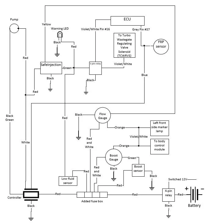
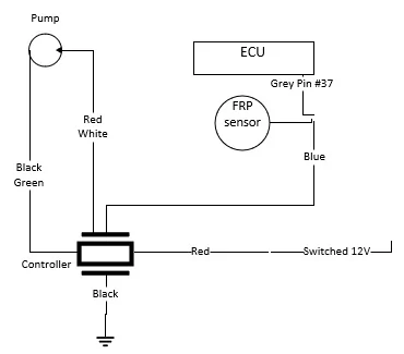
I reused most of the plumbing and wiring from the AEM V2 and ProMeth multi-port install, so I'll just highlight the differences as I don't think I saw any WMI installation guide posted on this forum for systems that utilized FRP sensor. This should also help folks with installations of other systems that also reference FRP, such as Aquamist.
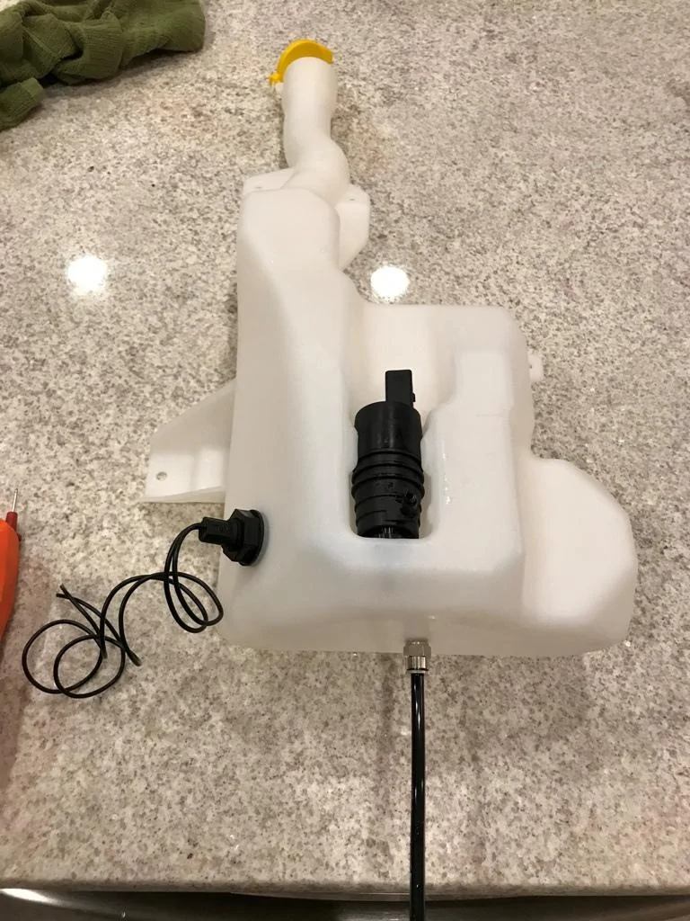
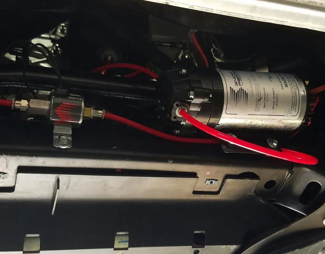
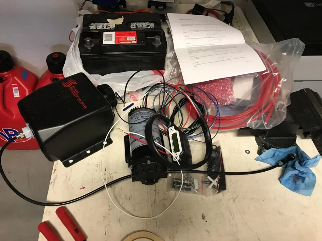
The first thing to do is to bench test the system as you don't want to find out that it's DOA after the installation. I first tested the pump by hooking it directly to the battery. Then I hooked the pump up to the controller, set the controller to trigger at 1 PSI, and blew into the boost reference tubing to ensure that it read the pressure and triggered the pump.

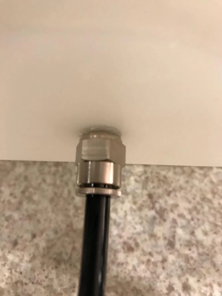
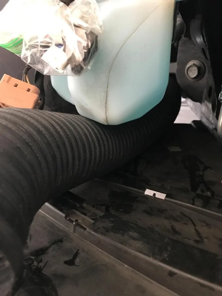
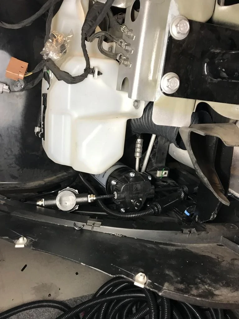
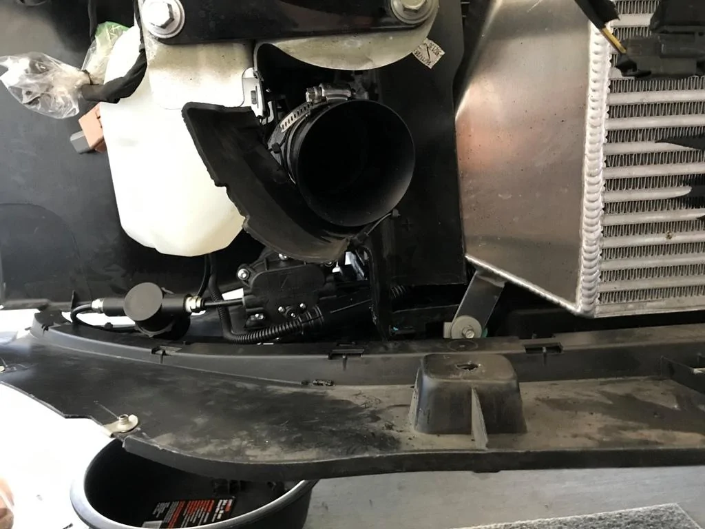
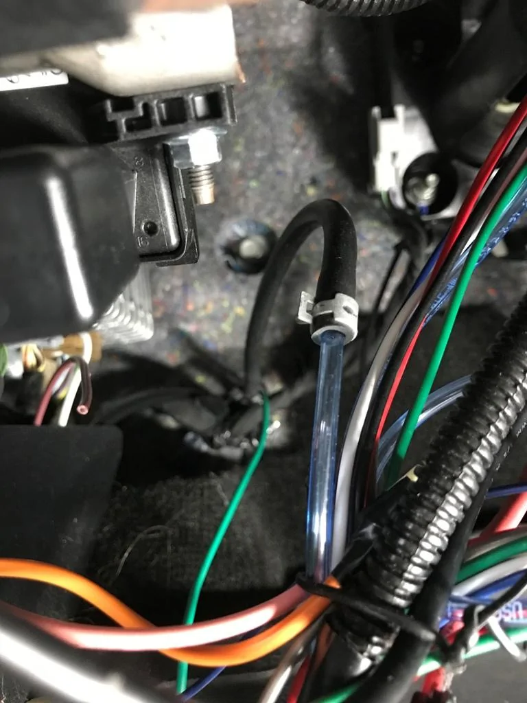
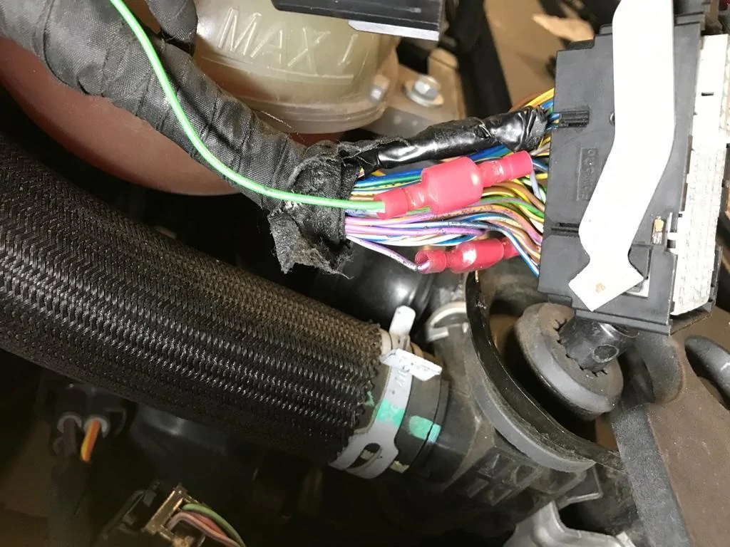
Clear boost pressure reference tubing fits tightly into the existing vacuum line used by AEM V2 controller. I put a small clamp on it to ensure that it doesn't pop off during boost. The wiring looks like a rat's nest right now as I'm holding off on trimming and soldering the connections until I'm good with the current mounting location. Meanwhile, I just rolled them up with twist ties and trucked them out of the way.

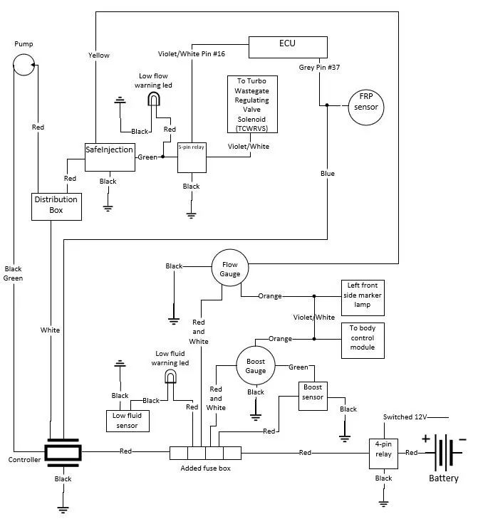
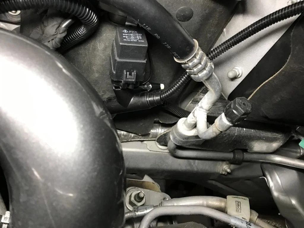
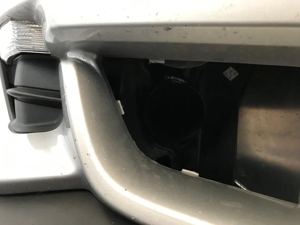
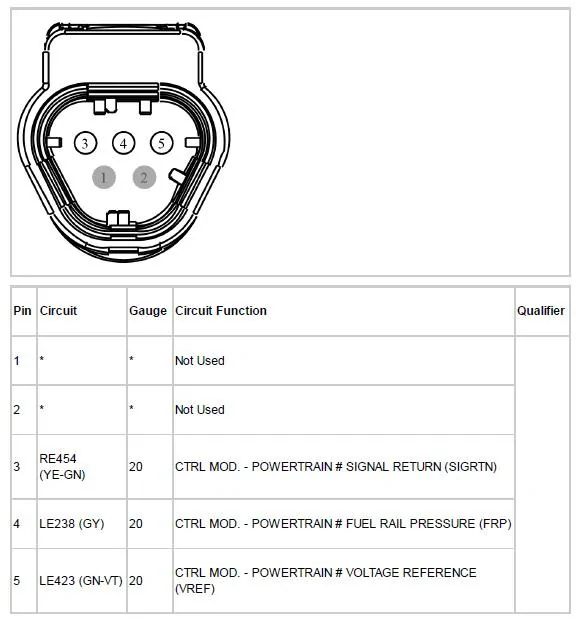
The final step was to tap into the wire carrying the FRP data. One possible location is at the FRP sensor, which's locate near the throttle body at the end of the fuel rail. Middle gray wire is the one to tap. There isn't much of slack in the wiring so it'll be difficult to do any splices without taking the intake manifold off, but it's much easier to locate the wire here than at the ECU harness side.

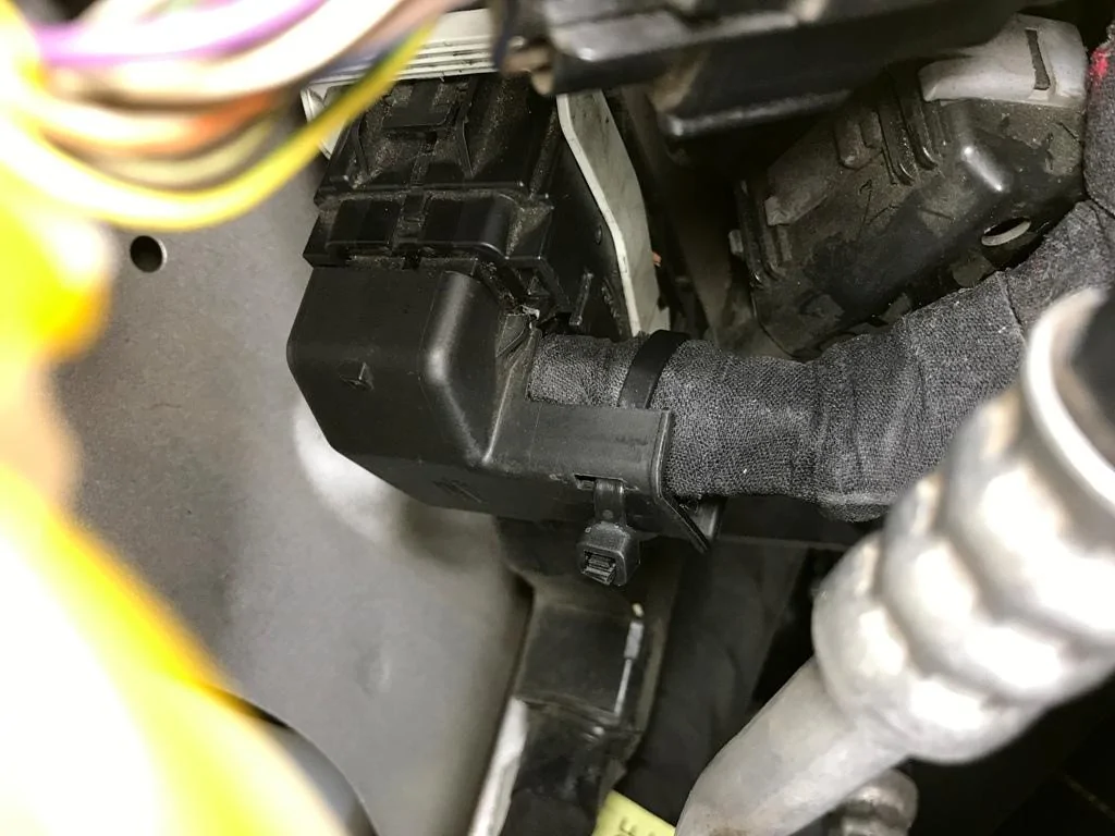
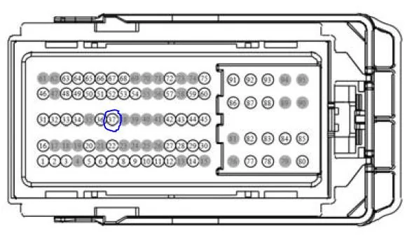
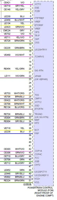
I chose to tap by the ECU harness as I tapped into other wires in the past at that location without issues. Pin 37 is the one to use. Note that the factory repair manual refers to a blue wire but the actual wire is gray, just like at the sensor (at least for my 2015). Grayed out circles on the harness diagram are pins without wires, so it's easy to see which one's #37 in the middle row.


I used a temporary connection/splice for in case I made any mistakes. The plan is to go back and solder the connection/splice once the long-term test shows no issues.
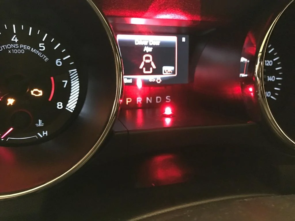
I fired up the car once everything was hooked back up. Fortunately, I didn't see any CELs and the controller displayed FRP percentage.
A short test drive showed that everything seems to be working fine. Other than setting the boost to start at 3 PSI and max at 22 PSI, I left the other settings at default for now.
Few more FRP sensor facts:
From the factory repair manual, this allowed me to understand why WMI systems for DI reference FRP instead of fuel injector pulse width:
FUEL RAIL PRESSURE (FRP) SENSOR
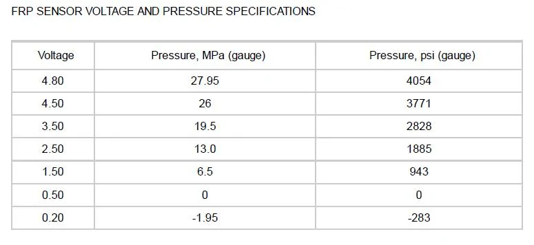
The FRP sensor is a diaphragm strain gauge device. The FRP sensor measures the pressure difference between the fuel rail and atmospheric pressure. The FRP sensor nominal output varies between 0.5 and 4.5 volts, with 0.5 volts corresponding to 0 MPa (0 psi) gauge and 4.5 volts corresponding to 26 MPa (3771 psi) gauge. The sensor can read vacuum and may lower the output voltage to slightly below 0.5 volts. This condition is normal and is usually the case after several hours of cold soak before the vehicle dome light is turned ON. The FP assembly is energized at the same time the dome light is commanded ON. A disabled or malfunctioning dome light does not affect the FP assembly control.
The FRP sensor is located on the fuel rail and provides a feedback signal to indicate the fuel rail pressure to the PCM. The PCM uses the FRP signal to command the correct injector timing and pulse width for correct fuel delivery at all speed and load conditions. The FRP sensor, along with the fuel volume regulator (part of the fuel injection pump), form a closed loop fuel pressure control system. An electrically faulted FRP sensor results in the deactivation of the fuel injection pump. Fuel pressure to injectors is then provided only by the FP assembly. When the fuel injection pump is de-energized and the injectors are active, the fuel rail pressure is approximately 70 kPa (10 psi) lower than FP assembly pressure due to the pressure drop across the fuel injection pump. Thus, if the FP assembly pressure is 448 kPa (65 psi), then the fuel rail pressure would be approximately 379 kPa (55 psi) if the injectors are active.

I reused most of the plumbing and wiring from the AEM V2 and ProMeth multi-port install, so I'll just highlight the differences as I don't think I saw any WMI installation guide posted on this forum for systems that utilized FRP sensor. This should also help folks with installations of other systems that also reference FRP, such as Aquamist.
The first thing to do is to bench test the system as you don't want to find out that it's DOA after the installation. I first tested the pump by hooking it directly to the battery. Then I hooked the pump up to the controller, set the controller to trigger at 1 PSI, and blew into the boost reference tubing to ensure that it read the pressure and triggered the pump.
Clear boost pressure reference tubing fits tightly into the existing vacuum line used by AEM V2 controller. I put a small clamp on it to ensure that it doesn't pop off during boost. The wiring looks like a rat's nest right now as I'm holding off on trimming and soldering the connections until I'm good with the current mounting location. Meanwhile, I just rolled them up with twist ties and trucked them out of the way.
The final step was to tap into the wire carrying the FRP data. One possible location is at the FRP sensor, which's locate near the throttle body at the end of the fuel rail. Middle gray wire is the one to tap. There isn't much of slack in the wiring so it'll be difficult to do any splices without taking the intake manifold off, but it's much easier to locate the wire here than at the ECU harness side.
I chose to tap by the ECU harness as I tapped into other wires in the past at that location without issues. Pin 37 is the one to use. Note that the factory repair manual refers to a blue wire but the actual wire is gray, just like at the sensor (at least for my 2015). Grayed out circles on the harness diagram are pins without wires, so it's easy to see which one's #37 in the middle row.
I used a temporary connection/splice for in case I made any mistakes. The plan is to go back and solder the connection/splice once the long-term test shows no issues.
I fired up the car once everything was hooked back up. Fortunately, I didn't see any CELs and the controller displayed FRP percentage.
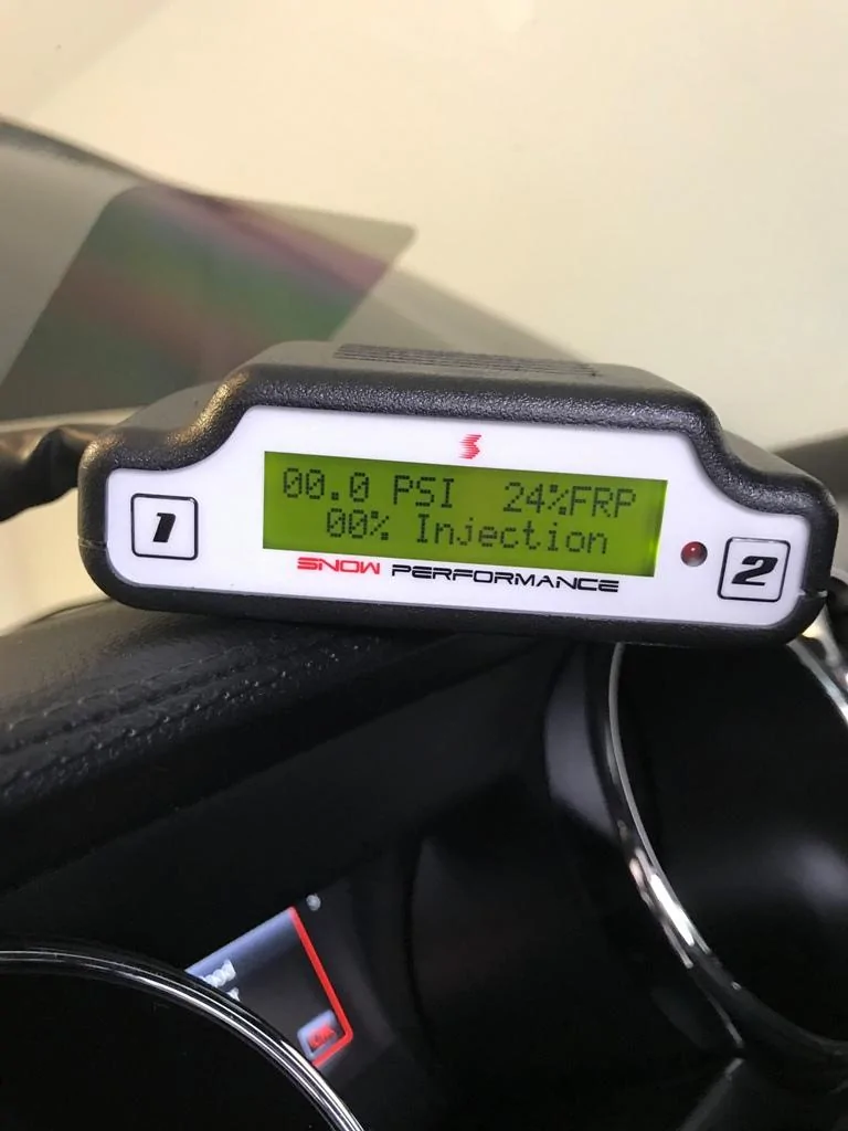
A short test drive showed that everything seems to be working fine. Other than setting the boost to start at 3 PSI and max at 22 PSI, I left the other settings at default for now.
Few more FRP sensor facts:
From the factory repair manual, this allowed me to understand why WMI systems for DI reference FRP instead of fuel injector pulse width:
FUEL RAIL PRESSURE (FRP) SENSOR
The FRP sensor is a diaphragm strain gauge device. The FRP sensor measures the pressure difference between the fuel rail and atmospheric pressure. The FRP sensor nominal output varies between 0.5 and 4.5 volts, with 0.5 volts corresponding to 0 MPa (0 psi) gauge and 4.5 volts corresponding to 26 MPa (3771 psi) gauge. The sensor can read vacuum and may lower the output voltage to slightly below 0.5 volts. This condition is normal and is usually the case after several hours of cold soak before the vehicle dome light is turned ON. The FP assembly is energized at the same time the dome light is commanded ON. A disabled or malfunctioning dome light does not affect the FP assembly control.
The FRP sensor is located on the fuel rail and provides a feedback signal to indicate the fuel rail pressure to the PCM. The PCM uses the FRP signal to command the correct injector timing and pulse width for correct fuel delivery at all speed and load conditions. The FRP sensor, along with the fuel volume regulator (part of the fuel injection pump), form a closed loop fuel pressure control system. An electrically faulted FRP sensor results in the deactivation of the fuel injection pump. Fuel pressure to injectors is then provided only by the FP assembly. When the fuel injection pump is de-energized and the injectors are active, the fuel rail pressure is approximately 70 kPa (10 psi) lower than FP assembly pressure due to the pressure drop across the fuel injection pump. Thus, if the FP assembly pressure is 448 kPa (65 psi), then the fuel rail pressure would be approximately 379 kPa (55 psi) if the injectors are active.
Sponsored