Juben
Well-Known Member
- Joined
- Jan 29, 2015
- Threads
- 35
- Messages
- 2,519
- Reaction score
- 809
- Location
- Chattanooga, TN
- First Name
- Justin
- Vehicle(s)
- 2015 EcoBoost Mustang (AT) w/PP
- Thread starter
- #1
TOOLS NEEDED FOR INSTALLATION:
(1) Ratchet (1/4”)
(1) 7mm Deep Socket
(1) 8mm Deep Socket
(1) 10mm Deep Socket
(1) 11mm Deep Socket
(1) T25 Torx Bit (Fitting Screwdriver or Small Ratchet)
(1) T27 Torx Bit (Fitting Screwdriver or Small Ratchet)
(1) 6” Socket Extention (1/4” drive)
(1) Flat-blade Screwdriver
(1) Large Pliers
(1) Can of Penetrating Lubricant (WD-40/PB Blaster)
(1) Floor Jack, Lift, or Ramps
***DISCONNECT THE NEGATIVE BATTERY CABLE BEFORE BEGINNING INSTALLATION***
The car battery stores a tremendous amount of energy and must be treated with respect. Disconnect the NEGATIVE, BLACK, wire from the car's battery. Be extremely careful NOT to short the battery with your tools while removing the negative cable. Shorting the battery by touching the terminal will almost certainly cause severe burns, a fire, or even an explosion. FYI, the reason to remove the negative terminal of the battery is so that if the wrench were to slip while on the nut of the battery terminal, and accidentally contact the frame of the car (ground) the result would not be a short from positive to ground, but a much less harmful short from negative-to-negative. Be careful not to slip and hit anything. The battery is lcoated under a cover in the back of the engine bay on the passenger's side.
Step 1: Jack each side of the Mustang Ecoboost up to an amount that will allow you to get under the front of the vehicle. Place one jack stand firmly underneath both sides of the Mustang for safety and support. A lift or ramps can also be used in place of the aforementioned.
Step 2: Remove the engine cover on top of the engine by removing (4) bolts. There are (2) 8mm bolts. One in the lower left-hand corner of the cover and one in the upper right-hand corner of the cover. There are also (2) 10mm bolts. One in the upper left-hand corner of the cover and one in the lower right-hand corner of the cover. Once all four bolts are removed, the engine can be pulled upwards toward the hood and removed.

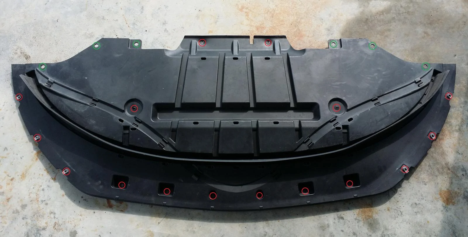
Step 3: Remove the lower splash cover from the bottom of the engine bay. The lower splash shield is held on by (16) 7mm bolts and (6) quick clips. The locations of the 7mm bolts are shown in red and the locations of the quick clips are shown in green.

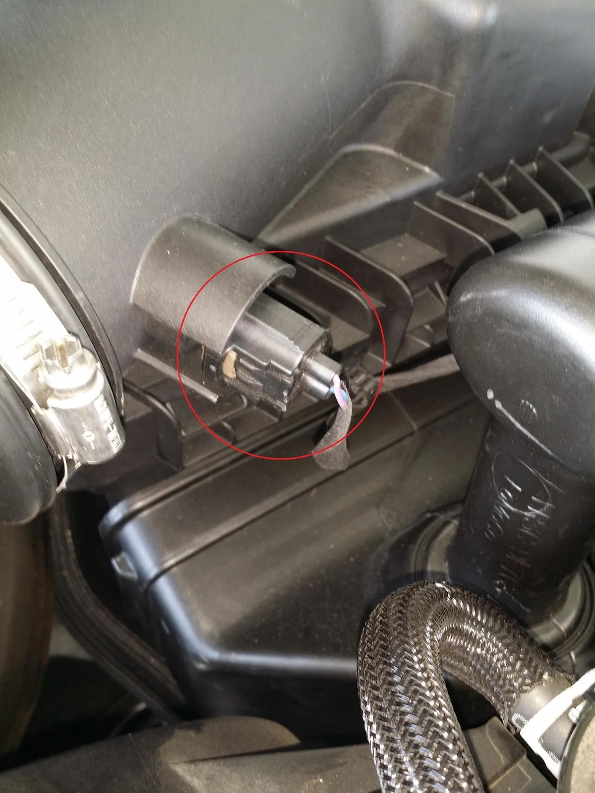
Step 4: Unplug the Intake Air Temperature (IAT) sensor harness and disconnect it from it's mounting point on the airbox.

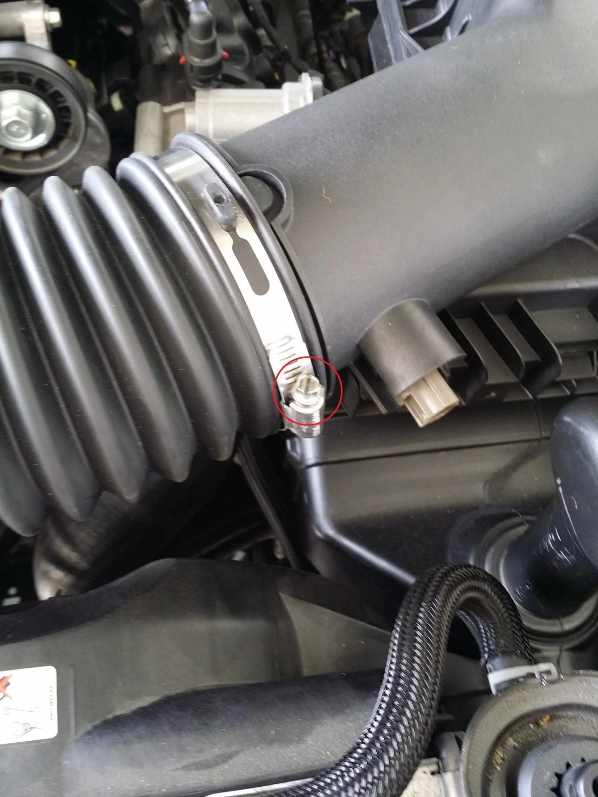
Step 5: Loosen the intake hose clamps on the turbo intake pipe where it attaches to the turbocharger and airbox. Both of the hose clamps can be loosened with either a 7mm socket or a flat-blade screwdriver.
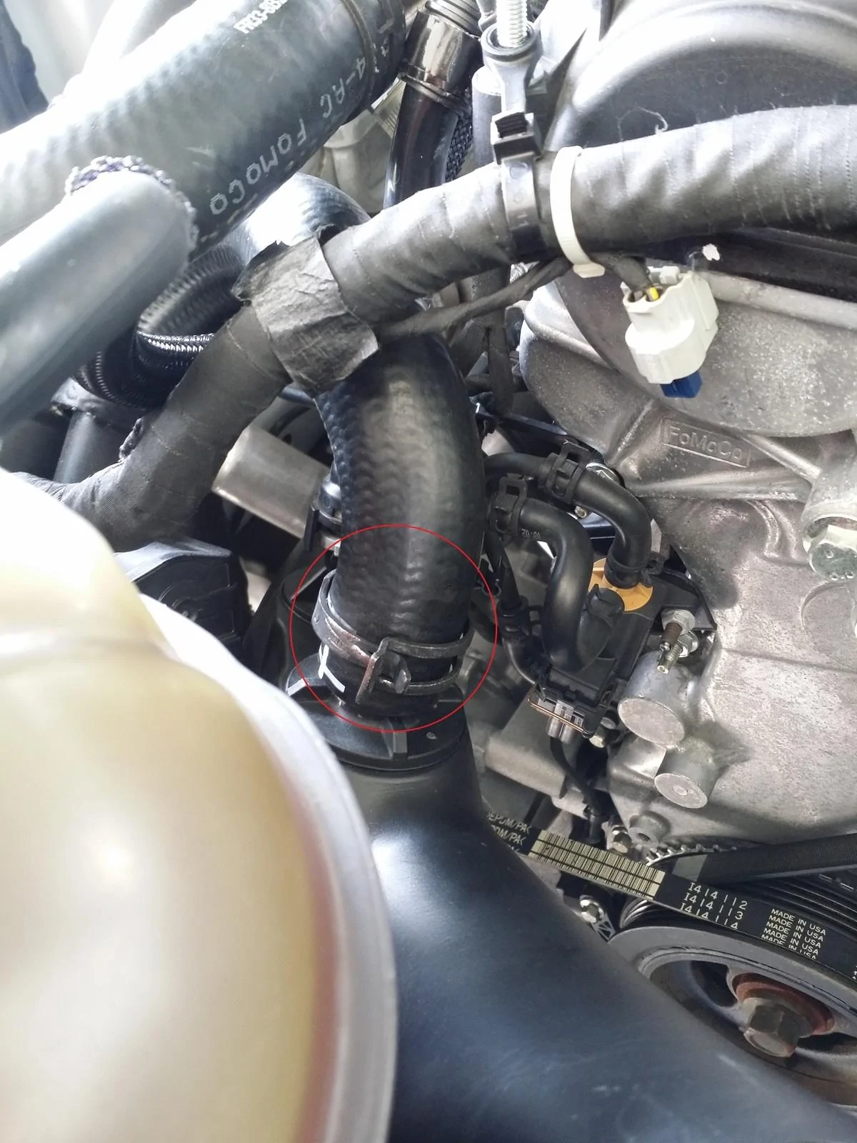
Step 6: Remove the recirculation hose from the factory BPV and the turbo intake pipe. The recirculation tube can be removed at both points by using a set of pliers. Grasp the hose clips with the pliers and wiggle the tube while pulling upwards on it.
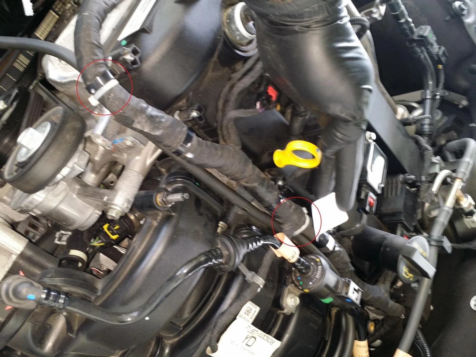
Step 7: Remove the PCV line attached to the turbo intake pipe. Press upwards and left on the gray tab to release it, then pull the line up and away from the turbo intake pipe.
Step 8: Remove the turbo intake pipe from the car and lay it to the side.
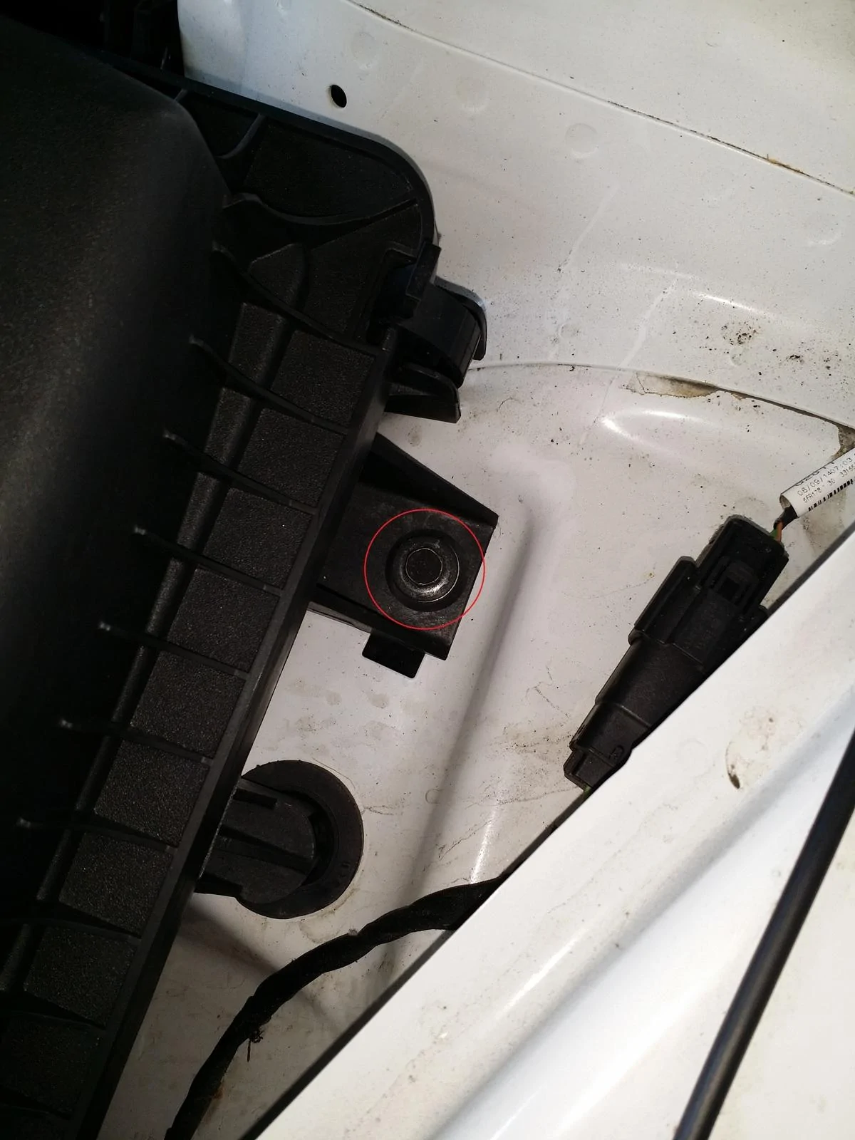
Step 9: Remove the 10mm bolt securing the air box to the engine bay. *NOTE: It is not necessary to remove the air box for the installation of the Exhale™ pipe. However, it does provide a considerable amount of room to work with and is recommended for easier installation and alignment of the Exhale™ pipe.
Step 10: Pull up and backwards (towards the rear of the car) to remove the air box.
Step 11: Release the wiring harness attachment points on the flange of the factory BPV. Pull upwards toward the hood and firmly wiggle the harness near the each of the plugs. *NOTE: The use of pliers may aid in releasing the harness.
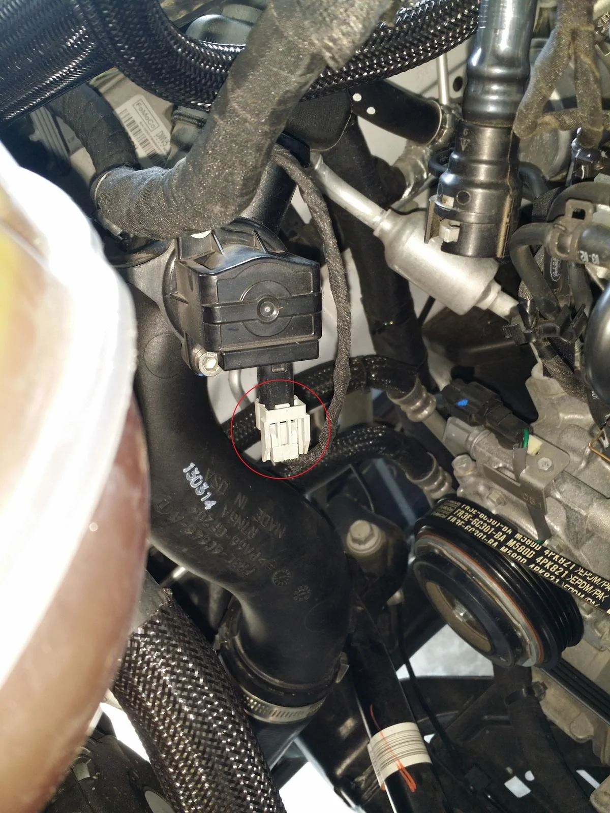
Step 12: Unplug the factory BPV connection and zip-tie it to the wiring harness.
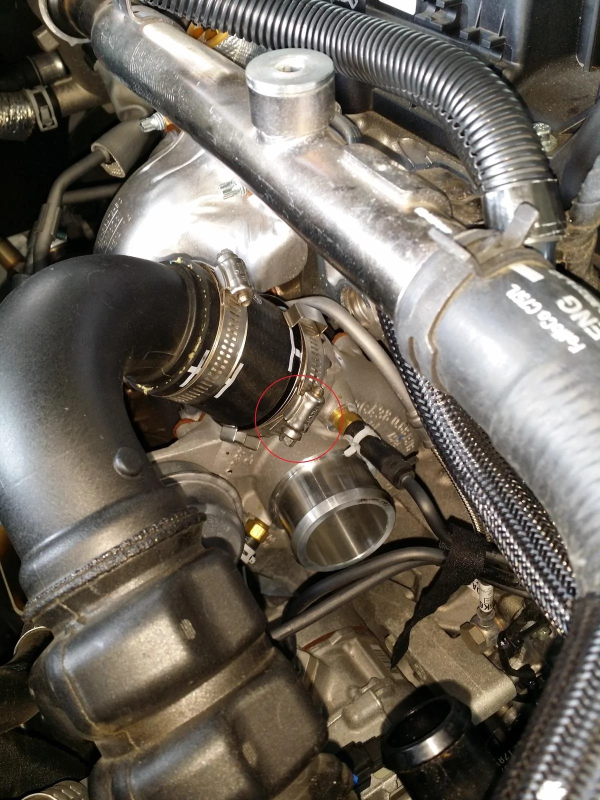
Step 13: Loosen the hose clamps on the passenger side (hot) charge pipe and remove the pipe at both connections, the turbo and the intercooler. *NOTE: An aftermarket intercooler has been installed on this car. As such, the lower connection at the intercooler will appear different. It is noted though that the connection will still be in the same location and can be removed as shown.
Step 14: Loosen the hose clamps on the driver side (cold) charge pipe and remove the pipe at both connections, the throttle body and the intercooler. *NOTE: An aftermarket intercooler has been installed on this car. As such, the lower connection at the intercooler will appear different. It is noted though that the connection will still be in the same location and can be removed as shown.
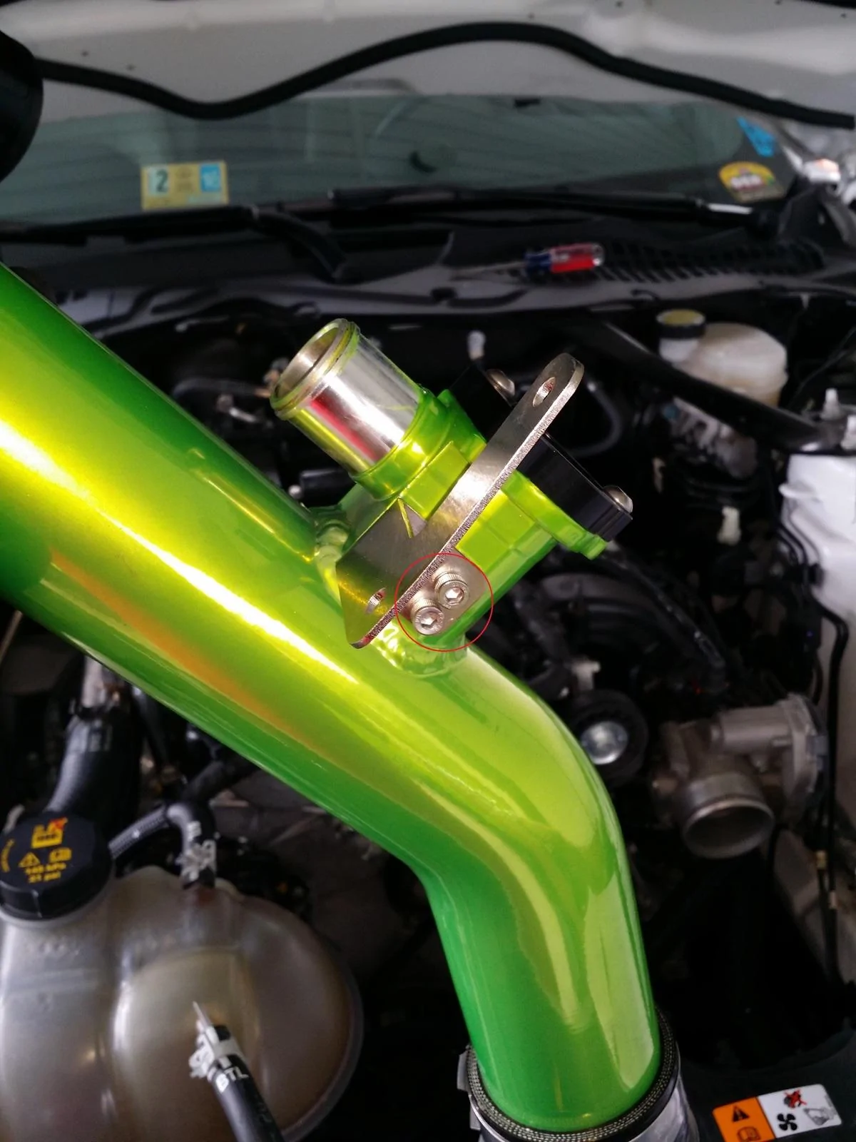
Step 15: Attach the L-shaped bracket to the OEcharge™ pipe using the supplied T25 Torx screws and block off the factory BPV port with the included cover (or plug).
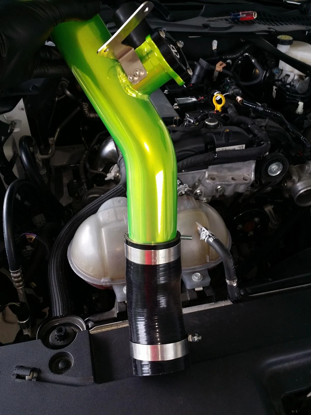
Step 16: Install the hose connections and clamps loosely on the OEcharge™ pipe and install the pipe. The hose clamp connection bolts are 11mm *NOTE: Applying a light coat of WD-40 may help with the installation of the hose connections on the charge pipe and also with adjustments to the pipe(s) during the installation. It is also noted that starting with the lower connection will help with the installation.
Step 17: Reinstall the factory wiring harness plugs into the L-shaped bracket on the OEcharge™ pipe.
Step 18: Install the Tial (or HKS) BOV on the Exhale™ pipe. *NOTE: Position the supplied o-ring within the Tial box between the flange on the Exhale™ pipe and the Tial BOV itself. Make sure that the o-ring seats properly when the two parts are fitted together and ensure that the o-ring is not pinched.
Step 19: Install the hose connections and clamps loosely on the Exhale™ pipe and install the pipe. The hose clamp connection bolts are 11mm. *NOTE: Applying a light coat of WD-40 may help with the installation of the hose connections on the charge pipe and also with adjustments to the pipe(s) during the installation. It is also noted that starting with the lower connection will help with the installation.
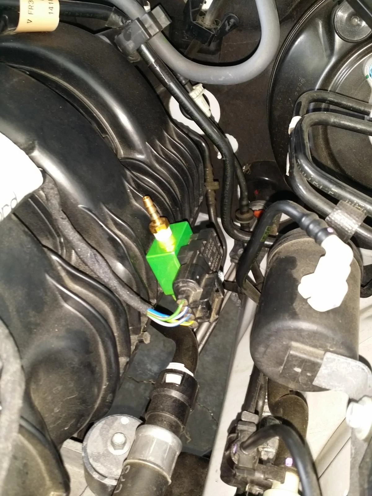
Step 20: Unplug the MAP sensor on the intake manifold and unbolt it with a T27 Torx bit.
Step 21: Install the 3/16 x 1/8 hose barb fitting into the MAP sensor adapter and install the MAP sensor into the top of the adapter. *NOTE: The use of Telfon tape to seal the connection point is recommended.
Step 22: Install the new MAP sensor and adapter assembly onto the intake manifold and secure the assembly with the supplied (longer) screw and reattach the MAP sensor plug. *NOTE: The new longer screw is also a T27 Torx screw.
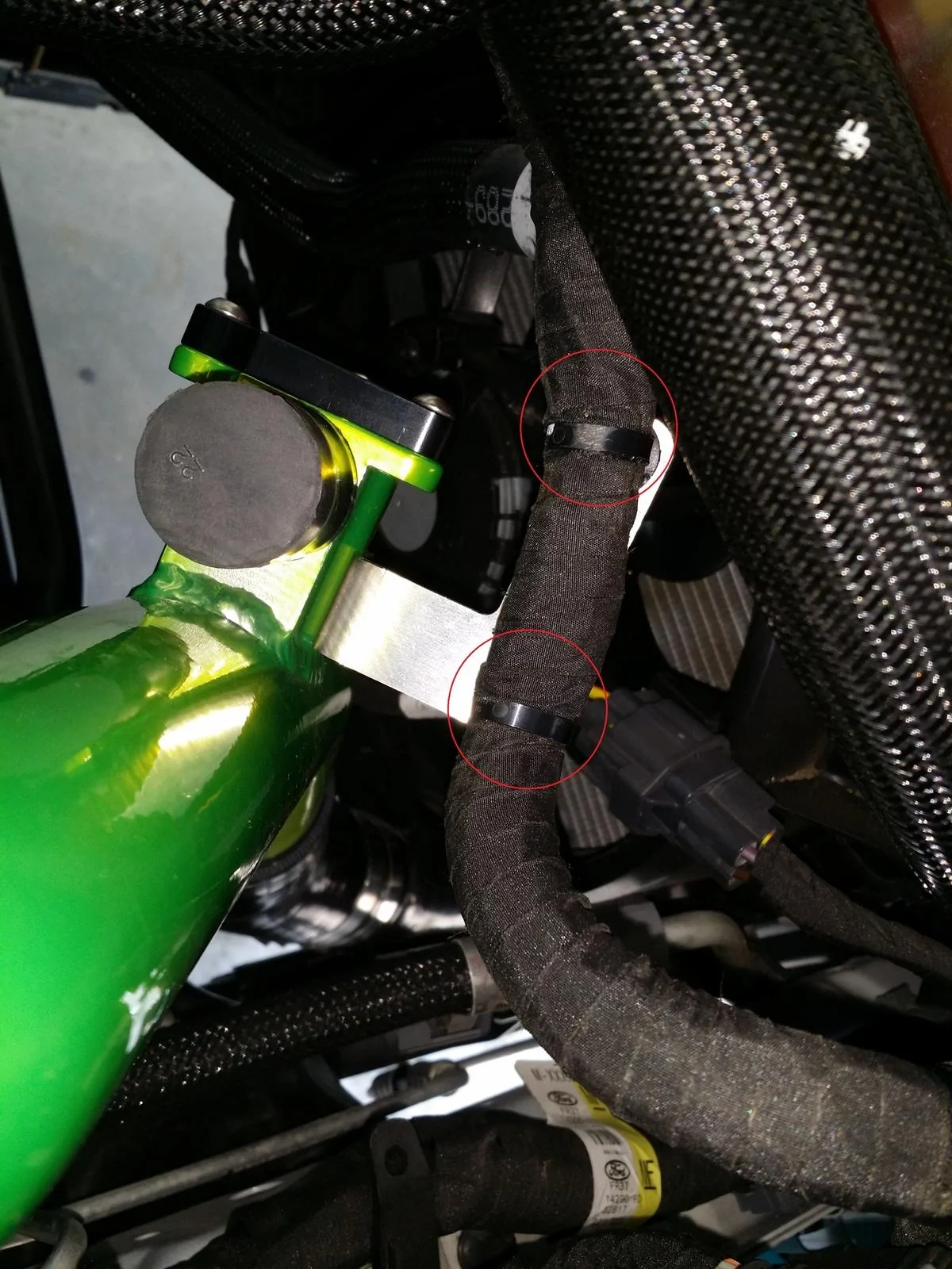
Step 23: Install the supplied vacuum line from the Tial BOV to the MAP sensor adapter on the intake manifold. The route chosen in this guide follows the factory wiring harness and is attached along the harness by zip-ties.

Step 24: Reinstall the turbo intake pipe and it's airbox (if removed) by following Step Nos. 4 through 10 in reverse and reinstall the lower splash shield by following Step No. 3 in reverse.
Step 25: Lower the car off the jack stands and clean up any used tools. Once the vehicle is started, check the connection points for any leaks. If any of the connections are found to be loose or improperly positioned, you may have to tighen or reposition the connection.
START THE VEHICLE AND TAKE OFF!
(1) Ratchet (1/4”)
(1) 7mm Deep Socket
(1) 8mm Deep Socket
(1) 10mm Deep Socket
(1) 11mm Deep Socket
(1) T25 Torx Bit (Fitting Screwdriver or Small Ratchet)
(1) T27 Torx Bit (Fitting Screwdriver or Small Ratchet)
(1) 6” Socket Extention (1/4” drive)
(1) Flat-blade Screwdriver
(1) Large Pliers
(1) Can of Penetrating Lubricant (WD-40/PB Blaster)
(1) Floor Jack, Lift, or Ramps
***DISCONNECT THE NEGATIVE BATTERY CABLE BEFORE BEGINNING INSTALLATION***
The car battery stores a tremendous amount of energy and must be treated with respect. Disconnect the NEGATIVE, BLACK, wire from the car's battery. Be extremely careful NOT to short the battery with your tools while removing the negative cable. Shorting the battery by touching the terminal will almost certainly cause severe burns, a fire, or even an explosion. FYI, the reason to remove the negative terminal of the battery is so that if the wrench were to slip while on the nut of the battery terminal, and accidentally contact the frame of the car (ground) the result would not be a short from positive to ground, but a much less harmful short from negative-to-negative. Be careful not to slip and hit anything. The battery is lcoated under a cover in the back of the engine bay on the passenger's side.
Step 1: Jack each side of the Mustang Ecoboost up to an amount that will allow you to get under the front of the vehicle. Place one jack stand firmly underneath both sides of the Mustang for safety and support. A lift or ramps can also be used in place of the aforementioned.
Step 2: Remove the engine cover on top of the engine by removing (4) bolts. There are (2) 8mm bolts. One in the lower left-hand corner of the cover and one in the upper right-hand corner of the cover. There are also (2) 10mm bolts. One in the upper left-hand corner of the cover and one in the lower right-hand corner of the cover. Once all four bolts are removed, the engine can be pulled upwards toward the hood and removed.

Step 3: Remove the lower splash cover from the bottom of the engine bay. The lower splash shield is held on by (16) 7mm bolts and (6) quick clips. The locations of the 7mm bolts are shown in red and the locations of the quick clips are shown in green.
Step 4: Unplug the Intake Air Temperature (IAT) sensor harness and disconnect it from it's mounting point on the airbox.

Step 5: Loosen the intake hose clamps on the turbo intake pipe where it attaches to the turbocharger and airbox. Both of the hose clamps can be loosened with either a 7mm socket or a flat-blade screwdriver.

Step 6: Remove the recirculation hose from the factory BPV and the turbo intake pipe. The recirculation tube can be removed at both points by using a set of pliers. Grasp the hose clips with the pliers and wiggle the tube while pulling upwards on it.

Step 7: Remove the PCV line attached to the turbo intake pipe. Press upwards and left on the gray tab to release it, then pull the line up and away from the turbo intake pipe.

Step 8: Remove the turbo intake pipe from the car and lay it to the side.
Step 9: Remove the 10mm bolt securing the air box to the engine bay. *NOTE: It is not necessary to remove the air box for the installation of the Exhale™ pipe. However, it does provide a considerable amount of room to work with and is recommended for easier installation and alignment of the Exhale™ pipe.
Step 10: Pull up and backwards (towards the rear of the car) to remove the air box.
Step 11: Release the wiring harness attachment points on the flange of the factory BPV. Pull upwards toward the hood and firmly wiggle the harness near the each of the plugs. *NOTE: The use of pliers may aid in releasing the harness.

Step 12: Unplug the factory BPV connection and zip-tie it to the wiring harness.

Step 13: Loosen the hose clamps on the passenger side (hot) charge pipe and remove the pipe at both connections, the turbo and the intercooler. *NOTE: An aftermarket intercooler has been installed on this car. As such, the lower connection at the intercooler will appear different. It is noted though that the connection will still be in the same location and can be removed as shown.

Step 14: Loosen the hose clamps on the driver side (cold) charge pipe and remove the pipe at both connections, the throttle body and the intercooler. *NOTE: An aftermarket intercooler has been installed on this car. As such, the lower connection at the intercooler will appear different. It is noted though that the connection will still be in the same location and can be removed as shown.


Step 15: Attach the L-shaped bracket to the OEcharge™ pipe using the supplied T25 Torx screws and block off the factory BPV port with the included cover (or plug).

Step 16: Install the hose connections and clamps loosely on the OEcharge™ pipe and install the pipe. The hose clamp connection bolts are 11mm *NOTE: Applying a light coat of WD-40 may help with the installation of the hose connections on the charge pipe and also with adjustments to the pipe(s) during the installation. It is also noted that starting with the lower connection will help with the installation.

Step 17: Reinstall the factory wiring harness plugs into the L-shaped bracket on the OEcharge™ pipe.
Step 18: Install the Tial (or HKS) BOV on the Exhale™ pipe. *NOTE: Position the supplied o-ring within the Tial box between the flange on the Exhale™ pipe and the Tial BOV itself. Make sure that the o-ring seats properly when the two parts are fitted together and ensure that the o-ring is not pinched.

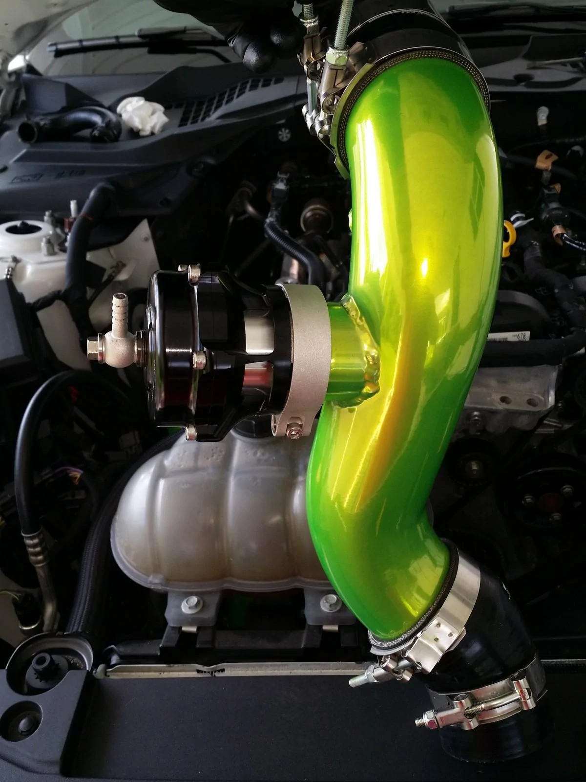
Step 19: Install the hose connections and clamps loosely on the Exhale™ pipe and install the pipe. The hose clamp connection bolts are 11mm. *NOTE: Applying a light coat of WD-40 may help with the installation of the hose connections on the charge pipe and also with adjustments to the pipe(s) during the installation. It is also noted that starting with the lower connection will help with the installation.


Step 20: Unplug the MAP sensor on the intake manifold and unbolt it with a T27 Torx bit.

Step 21: Install the 3/16 x 1/8 hose barb fitting into the MAP sensor adapter and install the MAP sensor into the top of the adapter. *NOTE: The use of Telfon tape to seal the connection point is recommended.

Step 22: Install the new MAP sensor and adapter assembly onto the intake manifold and secure the assembly with the supplied (longer) screw and reattach the MAP sensor plug. *NOTE: The new longer screw is also a T27 Torx screw.
Step 23: Install the supplied vacuum line from the Tial BOV to the MAP sensor adapter on the intake manifold. The route chosen in this guide follows the factory wiring harness and is attached along the harness by zip-ties.


Step 24: Reinstall the turbo intake pipe and it's airbox (if removed) by following Step Nos. 4 through 10 in reverse and reinstall the lower splash shield by following Step No. 3 in reverse.
Step 25: Lower the car off the jack stands and clean up any used tools. Once the vehicle is started, check the connection points for any leaks. If any of the connections are found to be loose or improperly positioned, you may have to tighen or reposition the connection.
START THE VEHICLE AND TAKE OFF!
Sponsored