Sponsored

Shelby Styled Shift Light

Mastodon2k

Active Member
Joined
Apr 12, 2020
Threads
2
Messages
31
Reaction score
32
Location
Nevada
First Name
Jacob
Vehicle(s)
2016 Mustang GT
A little background first: I have a ‘16 GT with Adaptive Cruise. For those unaware, that means my car came with a collision avoidance system that includes a HUD. Pretty much it lights up a series of LEDs in the dash, that reflect off the windshield to catch your attention. It’s a pretty smart idea, but also a missed opportunity. And the way Car and Driver reports it, I’m not the only one who thinks so:
Shelby electrical engineer Mike Makled was inspired to design the system after triggering the forward-collision warning light in his personal Taurus SHO a few years back. “I thought, ‘Wait a minute, why don’t we use that technology for our shift light on the GT350?’ ” said Makled.

You can read the full story here.
Now, I’m not great when it comes to electrical engineering, but I do know a thing or two, and I’m halfway decent when it comes to computers and software. So, I felt like I could modify the existing hardware into working for both the Collision Avoidance system and as a Shelby styled shift light.

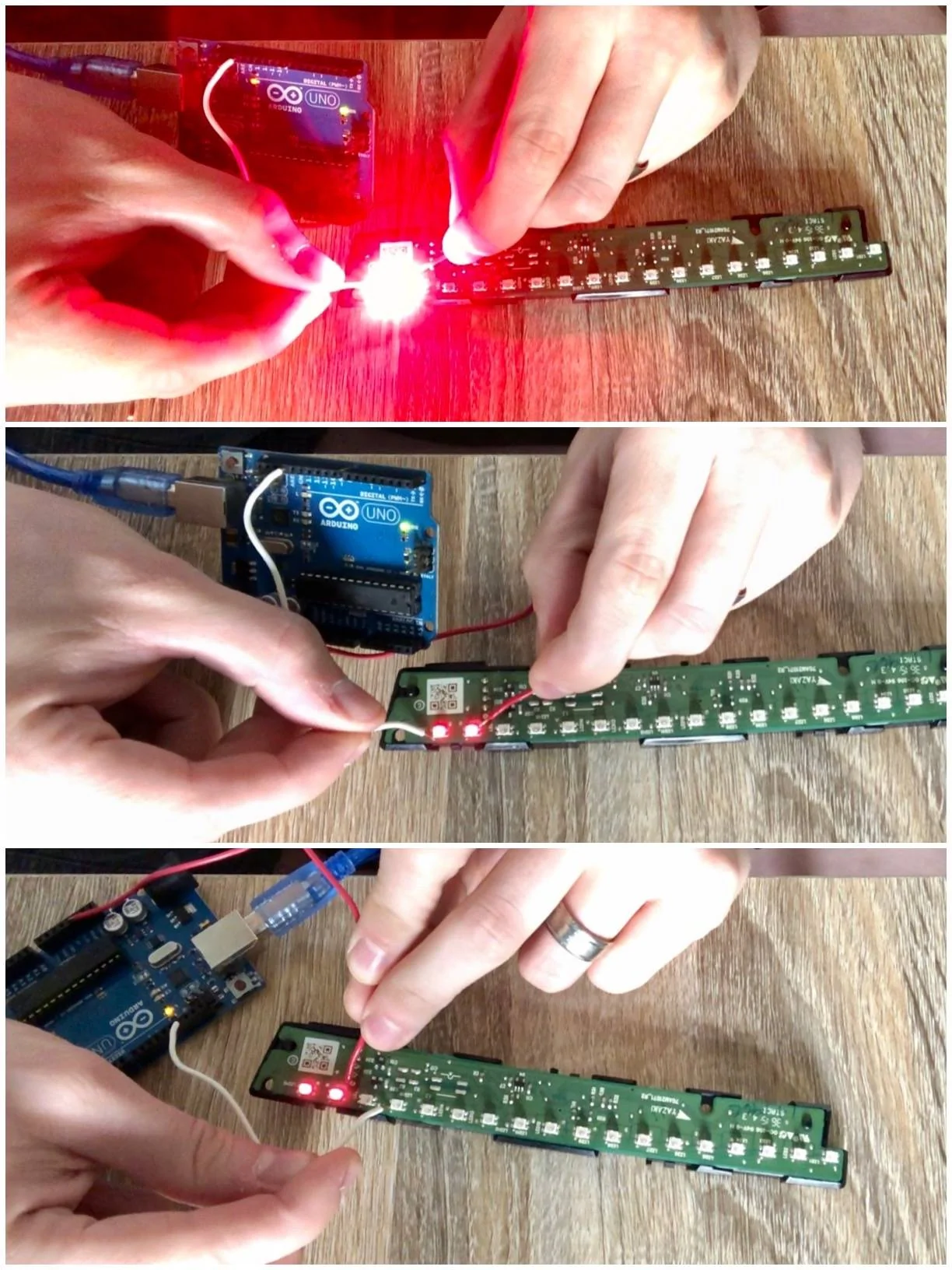
I've spent the past couple of weeks working off and on with this and I now have a working prototype. All that's left is to clean everything up and install it full-time into the car. And while my final solution isn’t quite as clean as I wanted, it’ll all be hidden under the dash anyways, so who cares? The important thing is: it works. Even more, it's completely customizable through an iOS app. Colors, engine redlines, shift points, etc.


IMG_1476.jpg


Rather than making one extremely long post, or having several posts spread throughout the thread, I’m reserving the next 3 posts for myself to document it. I'm not selling this, but I will provide enough detail that you should be able to recreate it yourself. If you want to do this yourself, and don't have an ACC car, you can buy the new defroster grille and HUD module for less than $200. Don't think there's anything else needed, but I've been wrong before.
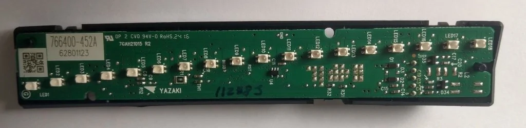
Defroster Grille
HR3Z-63044E82-AA

HUD Module
FR3Z-19G468-A


For those of you who just want the code to do it yourself, here's the GitHub repository for it. https://github.com/JMPhotos/OBDII-HUD/

If you want the iOS app, well...I'm not paying Apple $100 a year for it, so you'll have to get your own Mac, download XCode, get the code, and install it yourself.
Sponsored

 
Last edited:
OP
OP

Mastodon2k

Active Member
Joined
Apr 12, 2020
Threads
2
Messages
31
Reaction score
32
Location
Nevada
First Name
Jacob
Vehicle(s)
2016 Mustang GT
The standard Mustang HUD is a circuit board with 18 LED lights, and it's the same part number whether it's on a Shelby or not. However, at some point in time after Feb 2016, Ford redesigned the part and the older one is no longer available. Aside from the sweep of the curve between the two, I'm not certain of the differences between them. But mine is the older one. You can pick up the newer one for $60 from Tasca.

FR3T-19G468 (old part)
img_1003-jpg.jpg

FR3Z-19G468 (new part)
IMAG4123-20200525-171527547 (Custom).jpg


Both parts use a 4 pin connector to plug into the car like so:
1 - GND
2 - HS2 CAN -
3 - HS2 CAN +
4 - PWR (F66 in Battery Junction Box)

The GT350 Instrument Cluster provides the Tach signal for the GT350 shift light, but I didn't want to replace mine. (I like the MyColor, don't have a 8500 RPM redline, and can't come close to the 200MPH on its speedo.) Instead, I would read the RPM from the OBDII port, process it with an Arduino, and light up the LEDs myself.

My first thought was to run individual power cables to each LED. Kind of like a three-way lightswitch, if the Collision Avoidance activated, the LEDs would light as normal, and if the RPMs were right, the Arduino would also be able to light the LED. In testing, I found that wasn't easily accomplished. Or, at least I couldn't figure out how they were wired. I could get one LED to light, sometimes multiple would light. Other times, LEDs I wasn't even touching would light. I spent an entire day building an excel spreadsheet to map all the combinations, and I couldn't find any discernable pattern. So, I gave up on that route.

20200525_033508022_ios-jpeg.jpg


I thought about finding new LEDs online and building my own circuit for them, and even found almost identical ones online (Wurth Elektronik part #150141RS63140) but I'm not good at soldering things that small.

Instead, I went with the Adafruit NeoPixel. These are small multi-colored LEDs that use only 3 wires, regardless of how many LEDs you use. This makes it ideal for powering off of an Arudino. Even better, I could buy ready to go strips as dense as 144 lights per meter. For reference, the HUD is approximately 112 lights per meter. In the same space, the NeoPixels fit 23 LEDs.

1 - PWR (5V +)
2 - DATA (5V +)
3 - GND

I cut a new backing plate out of a DVD case and glued the LEDs in place. Since there are more LEDs than the HUD normally has, I attempted to expand the spacing between the LEDs. But, like I said, I'm not an electrical engineer and I'm not good at soldering small components. It ended up pretty ugly and didn't work.

IMG_1508 (Custom).jpg


I settled on using the strand as is, and cut it down to 23 LEDs, since that'd fill the same space. Glued the strand in place, and then used hot glue to secure the backing to the original hardware. I did have to cut a small hole in the original enclosure for my wires to escape, but that might not be necessary depending on your skills. It also won't be seen, so I don't really care. I am using hot glue after all, and that looks ugly, but for how it would sit in the car, none of it's seen.

The Bluetooth LE Shield not only gives a large area to solder my wires to, but allows communication with my iPhone. It's preassembled (minus the header pins) but uses several pins for it's own communication, so even though many look free, they're not. For the Data pin, I recommend Pin 6 since it's free and the default in Adafruit's NeoPixel example code.
  • Red: 5V (connecting to Arduino’s 5V)
  • White: GND (connecting to Arduino’s GND)
  • Green: Data (connecting to any available pin)
With the lights done, the next part is to read the OBDII data. The Freematics OBDII UART device has 4 pins, and is capable of powering the Arduino.

Power Connector (2-pin 2.54 Dupont connector)
  • Red: VCC (connecting to Arduino’s VIN)
  • Black: GND (connecting to Arduino’s GND)
Serial UART Data Connector (2-pin 2.54 Dupont connector)
  • White: Rx (connected to Arduino’s serial Tx)
  • Green: Tx (connected to Arduino’s serial Rx)
I soldered everything to the underside of the Shield, so that the cables would have less movement wedged between it and the Arduino.
IMG_1509 (Custom).jpg


Once all's said and done, this is the result. Upload the code, and install it into the car, and it's done!
IMG_1510 (Custom).jpg


This is it in the car, just sitting on the dash not actually installed, but you can see it work.


Parts Used
  1. Arduino Uno R3 (link) - $23 - Amazon (link)
  2. Adafruit Bluefruit LE Shield - $25 - Amazon (link)
  3. 144LED/m Addressable LED - $21 - Amazon (link)
  4. OBD-II Adapter - $40 - Freematics.com (link)
  5. Time - Priceless
 
Last edited:
OP
OP

Mastodon2k

Active Member
Joined
Apr 12, 2020
Threads
2
Messages
31
Reaction score
32
Location
Nevada
First Name
Jacob
Vehicle(s)
2016 Mustang GT
The great thing about an Arduino is that it's very easy to program. Yes it's code (C-programming language) but making an Arduino do what you want is significantly easier than writing a full Windows/OSX application. Primarily, this is because so many examples exist already that all you have to do is modify it instead of writing something from scratch. For instance, the library for reading OBDII data is here: https://github.com/stanleyhuangyc/ArduinoOBD/tree/master/libraries/OBD2UART

There's a lot of tutorials on how to program, and there's a lot of ways to format and organize code. So while I'm not going to get into the nuts and bolts of how to write a program, I will say that a basic program has 3 main areas: General Declarations, Setup, and Loop. You can see them in this example that simply lights up a single LED when the engine is higher than 3000RPM. On each processor cycle, the Loop function runs, reading the RPM and comparing it with the specified RPM. This technically, is an entire program that does basically what I want. I just need to light up more LEDs, and at other RPM.
Code:
#include <OBD2UART.h>

COBD obd;

void setup()
{
  // we'll use the debug LED as output
  pinMode(13, OUTPUT);
  // start serial communication
  obd.begin();
  // initiate OBD-II connection until success
  while (!obd.init());
}

void loop()
{
  int value;
  // save engine RPM in variable 'value', return true on success
  if (obd.readPID(PID_RPM, value)) {
    // light on LED on Arduino board when the RPM exceeds 3000
    digitalWrite(13, value > 3000 ? HIGH : LOW);
  }
}
Unlike the small LED that's on the Arduino used in the example above, the NeoPixels need a little prep work. Primarily, it needs to know how many LEDs you're using, what Pin you've connected to, and the specifics of your LED strand. Then, in the actual setup portion of the code, the strip has to be initialized.
Code:
#include <Adafruit_NeoPixel.h>

/*=========================================================================
    NEOPIXEL Config

      LED_COUNT         Number of LEDs in the NeoPixel strand
      LED_PIN           NeoPixel Control Pin
    
      Argument 1        Number of pixels in NeoPixel strip
      Argument 2        Arduino pin number (most are valid)
      Argument 3        Pixel type flags, add together as needed:
        NEO_KHZ800      800 KHz bitstream (most NeoPixel products w/WS2812 LEDs)
        NEO_KHZ400      400 KHz (classic 'v1' (not v2) FLORA pixels, WS2811 drivers)
        NEO_GRB         Pixels are wired for GRB bitstream (most NeoPixel products)
        NEO_RGB         Pixels are wired for RGB bitstream (v1 FLORA pixels, not v2)
        NEO_RGBW        Pixels are wired for RGBW bitstream (NeoPixel RGBW products)
    -----------------------------------------------------------------------*/
#define LED_COUNT 23
#define LED_PIN    6
Adafruit_NeoPixel strip(LED_COUNT, LED_PIN, NEO_GRB + NEO_KHZ800);

void setup() {
  strip.begin();           // INITIALIZE NeoPixel strip object (REQUIRED)
  strip.show();            // Turn OFF all pixels 
}
Controlling one of the NeoPixels takes three commands. .clear() resets the entire strip. .setPixelColor(led, .color(R,G,B)) sets a single LED, numbered 0 to LED_COUNT minus 1, and a specific color using the numbers 0-255 each for Red, Blue, and Green. And finally .show() shows the changes. All of these do what they sound like. To turn the 5th LED purple, it would look like this:
Code:
void loop() {
      strip.clear();
      strip.setPixelColor(4,strip.color(255,0,63);
      strip.show();
}
The Shelby shift HUD has 3 different styles, and I've done my best to replicate them. The first acts like a simple tachometer. Now, my car idles somewhere around 800 RPM, and I have a 6500 redline. We need to divide that entire span evenly across my 23 LEDs. So the question is, how many revs are there between each LED?
Code:
int RPM_interval = (REDLINE - 1000)/22;
Since we're reading fresh RPM data on each time the loop function runs, we can get the number of LEDs that should be lit by dividing the redline (minus our idle speed) by the interval number above, and adding 1. Then we loop through the that number of LEDs and set them to the right color. In this case, I want an Amber color.
Code:
void loop() {
  if (obd.readPID(PID_RPM, RPM))
  {
    if (RPM > 1000)
    {
      int LEDs_lit = floor((RPM-1000)/RPM_interval)+1;
  
      strip.clear();
      for(uint8_t i = 0; i<LEDs_lit; i++)
      { 
        strip.setPixelColor(i,strip.setPixelColor(255,63,0));
      }
      strip.show();
    }
  }
}
The Shelby also has a mode that simply lights up the entire strip once the RPM reaches a certain speed. This even easier, and works almost exactly like the sample code at the beginning of this post. To make it even easier, we'll use a different function that will the entire strip with a single color.
Code:
void loop() {
  if (obd.readPID(PID_RPM, RPM))
  {
    if (RPM>=REDLINE)
    {
      strip.clear();
      strip.fill(strip.setPixelColor(255,0,0));
      strip.show();
    }
  }
}
The final Shelby mode is most challenging, lighting up from both ends until it meets in the middle. Going one step further, and since the NeoPixels support it, I wanted to adjust colors as it approached the shift point. So, I did this one in two parts, one part inside the loop function that calls the second function. Again, we have to get the number of revs between each LED, and rather than starting at idle, I wanted this to start halfway through the RPM band. Since 23 is an odd number, and the first light is actually 2 LEDs, there's a total of 10 steps, making the interval look like this.
Code:
int RPM_interval = (REDLINE - (REDLINE/2))/10;
Now, like before we use the loop function to read the RPM on each cycle and compare it with our threshold values. If it's higher than the threshold, we pass the appropriate color to the HUD2 function (named so, because this is the 2nd option on the Shelby's IPC screen.)
Code:
void loop() {
  if (obd.readPID(PID_RPM, RPM))
  {
    strip.clear();
    if(RPM>=(REDLINE - (RPM_interval)))    //High RPM
    {
      HUD2(strip.Color(255,0,0)); //Red
    }
    else if(RPM>(REDLINE - (RPM_interval*4.0)))    //Mid-Range RPM
    {
      HUD2(strip.Color(255,63,0)); //Amber
    }
    else if(RPM>(REDLINE/2))    //Low RPM
    {
      HUD2(strip.Color(0,255,0)); //Green
    }
    strip.show();
  }
}
The HUD2 function is what configures each individual LED. Since I want the whole strip to change colors as the RPM increases, instead of just the new LEDs, it means a lot of repetition. For brevity, I'm only going to do the first and last couple of sections, and you should be able to infer the stuff inbetween.
Code:
void HUD2(uint32_t color)
{   
    if(RPM>REDLINE/2)
    {
      strip.setPixelColor(0,color);
      strip.setPixelColor(1,color);
      strip.setPixelColor(21,color);
      strip.setPixelColor(22,color);
    }
    if(RPM>REDLINE/2+RPM_interval)
    {
      strip.setPixelColor(0,color);
      strip.setPixelColor(1,color);
      strip.setPixelColor(2,color);
      strip.setPixelColor(20,color);
      strip.setPixelColor(21,color);
      strip.setPixelColor(22,color);
    }
    if(RPM>REDLINE/2+RPM_interval*2)
    {...}
    if(RPM>REDLINE/2+RPM_interval*3)
    {...}
...
    if(RPM>REDLINE/2+RPM_interval*8)
    {...}
    if(RPM>=REDLINE/2+RPM_interval*9)
    {
      strip.setPixelColor(0,color);
      strip.setPixelColor(1,color);
      strip.setPixelColor(2,color);
      strip.setPixelColor(3,color);
      strip.setPixelColor(4,color);
      strip.setPixelColor(5,color);
      strip.setPixelColor(6,color);
      strip.setPixelColor(7,color);
      strip.setPixelColor(8,color);
      strip.setPixelColor(9,color);
      strip.setPixelColor(10,color);
      strip.setPixelColor(12,color);
      strip.setPixelColor(13,color);
      strip.setPixelColor(14,color);
      strip.setPixelColor(15,color);
      strip.setPixelColor(16,color);
      strip.setPixelColor(17,color);
      strip.setPixelColor(18,color);
      strip.setPixelColor(19,color);
      strip.setPixelColor(20,color);
      strip.setPixelColor(21,color);
      strip.setPixelColor(22,color);
    }
    if(RPM>=REDLINE/2+RPM_interval*10)
    {
      strip.fill(color);
    }
}
And that's the gist of programming an Arduino to light up the LED based on RPM. Since this is still a work in progress for me, I'm not posting the completed code yet, but this should provide enough of a start that combining this with a tutorial or two should get you up and running.
 
Last edited:
OP
OP

Mastodon2k

Active Member
Joined
Apr 12, 2020
Threads
2
Messages
31
Reaction score
32
Location
Nevada
First Name
Jacob
Vehicle(s)
2016 Mustang GT
Alright, so obviously I don't want to plug a laptop into my car every time I want to make a simple change to the HUD, especially while I'm dialing it into my preferences. It'd be like needing to use Forscan to switch pages on the small digital display in the gauge cluster. So, I built an iPhone app to handle it for me and uses bluetooth to communicate back and forth with the Arduino. But, since the settings are configurable and not hard coded, I don't want to use the phone every time I drive. So, all of the settings are persistent, saved to the Arduino, and read by the iPhone each time it connects.

Considering how long the post was for the generic Arduino code, I'm definitely not posting the "how-to" for creating the iPhone app. Instead here's a demo of how the whole thing works:
 
Last edited:

Kermitz

Well-Known Member
Joined
Dec 22, 2018
Threads
32
Messages
771
Reaction score
808
Location
Vacaville CA
First Name
Seth
Vehicle(s)
2019 Mustang GT PP1 300A M6
Vehicle Showcase
1
Hopefully it's plug and play. I'm not a fan of cutting and splicing.
 

Sponsored

OP
OP

Mastodon2k

Active Member
Joined
Apr 12, 2020
Threads
2
Messages
31
Reaction score
32
Location
Nevada
First Name
Jacob
Vehicle(s)
2016 Mustang GT
Hopefully it's plug and play. I'm not a fan of cutting and splicing.
It's mostly plug and play, as far as the car is concerned, if you have Adaptive Cruise. Obviously wiring and programming the Arduino isn't, but the rest pretty much is. I did make a small cut on the original enclosure though, for the new wires to escape. Otherwise, I replaced the original LED strip and backing with new ones. If you don't have the Adaptive Cruise, then you'd have to do some cutting of the dash to make it fit.
 

JRedondox

Well-Known Member
Joined
Dec 24, 2015
Threads
11
Messages
325
Reaction score
451
Location
San Diego, CA
First Name
Jorge
Vehicle(s)
2015 Ford Mustang GT
you should sell
The great thing about an Arduino is that it's very easy to program. Yes it's code (C-programming language) but making an Arduino do what you want is significantly easier than writing a full Windows/OSX application. Primarily, this is because so many examples exist already that all you have to do is modify it instead of writing something from scratch. For instance, the library for reading OBDII data is here: https://github.com/stanleyhuangyc/ArduinoOBD/tree/master/libraries/OBD2UART

There's a lot of tutorials on how to program, and there's a lot of ways to format and organize code. So while I'm not going to get into the nuts and bolts of how to write a program, I will say that a basic program has 3 main areas: General Declarations, Setup, and Loop. You can see them in this example that simply lights up a single LED when the engine is higher than 3000RPM. On each processor cycle, the Loop function runs, reading the RPM and comparing it with the specified RPM. This technically, is an entire program that does basically what I want. I just need to light up more LEDs, and at other RPM.
Code:
#include <OBD2UART.h>

COBD obd;

void setup()
{
  // we'll use the debug LED as output
  pinMode(13, OUTPUT);
  // start serial communication
  obd.begin();
  // initiate OBD-II connection until success
  while (!obd.init());
}

void loop()
{
  int value;
  // save engine RPM in variable 'value', return true on success
  if (obd.readPID(PID_RPM, value)) {
    // light on LED on Arduino board when the RPM exceeds 3000
    digitalWrite(13, value > 3000 ? HIGH : LOW);
  }
}
Unlike the small LED that's on the Arduino used in the example above, the NeoPixels need a little prep work. Primarily, it needs to know how many LEDs you're using, what Pin you've connected to, and the specifics of your LED strand. Then, in the actual setup portion of the code, the strip has to be initialized.
Code:
#include <Adafruit_NeoPixel.h>

/*=========================================================================
    NEOPIXEL Config

      LED_COUNT         Number of LEDs in the NeoPixel strand
      LED_PIN           NeoPixel Control Pin
   
      Argument 1        Number of pixels in NeoPixel strip
      Argument 2        Arduino pin number (most are valid)
      Argument 3        Pixel type flags, add together as needed:
        NEO_KHZ800      800 KHz bitstream (most NeoPixel products w/WS2812 LEDs)
        NEO_KHZ400      400 KHz (classic 'v1' (not v2) FLORA pixels, WS2811 drivers)
        NEO_GRB         Pixels are wired for GRB bitstream (most NeoPixel products)
        NEO_RGB         Pixels are wired for RGB bitstream (v1 FLORA pixels, not v2)
        NEO_RGBW        Pixels are wired for RGBW bitstream (NeoPixel RGBW products)
    -----------------------------------------------------------------------*/
#define LED_COUNT 23
#define LED_PIN    6
Adafruit_NeoPixel strip(LED_COUNT, LED_PIN, NEO_GRB + NEO_KHZ800);

void setup() {
  strip.begin();           // INITIALIZE NeoPixel strip object (REQUIRED)
  strip.show();            // Turn OFF all pixels
}
Controlling one of the NeoPixels takes three commands. .clear() resets the entire strip. .setPixelColor(led, .color(R,G,B)) sets a single LED, numbered 0 to LED_COUNT minus 1, and a specific color using the numbers 0-255 each for Red, Blue, and Green. And finally .show() shows the changes. All of these do what they sound like. To turn the 5th LED purple, it would look like this:
Code:
void loop() {
      strip.clear();
      strip.setPixelColor(4,strip.color(255,0,63);
      strip.show();
}
The Shelby shift HUD has 3 different styles, and I've done my best to replicate them. The first acts like a simple tachometer. Now, my car idles somewhere around 800 RPM, and I have a 6500 redline. We need to divide that entire span evenly across my 23 LEDs. So the question is, how many revs are there between each LED?
Code:
int RPM_interval = (REDLINE - 1000)/22;
Since we're reading fresh RPM data on each time the loop function runs, we can get the number of LEDs that should be lit by dividing the redline (minus our idle speed) by the interval number above, and adding 1. Then we loop through the that number of LEDs and set them to the right color. In this case, I want an Amber color.
Code:
void loop() {
  if (obd.readPID(PID_RPM, RPM))
  {
    if (RPM > 1000)
    {
      int LEDs_lit = floor((RPM-1000)/RPM_interval)+1;
 
      strip.clear();
      for(uint8_t i = 0; i<LEDs_lit; i++)
      {
        strip.setPixelColor(i,strip.setPixelColor(255,63,0));
      }
      strip.show();
    }
  }
}
The Shelby also has a mode that simply lights up the entire strip once the RPM reaches a certain speed. This even easier, and works almost exactly like the sample code at the beginning of this post. To make it even easier, we'll use a different function that will the entire strip with a single color.
Code:
void loop() {
  if (obd.readPID(PID_RPM, RPM))
  {
    if (RPM>=REDLINE)
    {
      strip.clear();
      strip.fill(strip.setPixelColor(255,0,0));
      strip.show();
    }
  }
}
The final Shelby mode is most challenging, lighting up from both ends until it meets in the middle. Going one step further, and since the NeoPixels support it, I wanted to adjust colors as it approached the shift point. So, I did this one in two parts, one part inside the loop function that calls the second function. Again, we have to get the number of revs between each LED, and rather than starting at idle, I wanted this to start halfway through the RPM band. Since 23 is an odd number, and the first light is actually 2 LEDs, there's a total of 10 steps, making the interval look like this.
Code:
int RPM_interval = (REDLINE - (REDLINE/2))/10;
Now, like before we use the loop function to read the RPM on each cycle and compare it with our threshold values. If it's higher than the threshold, we pass the appropriate color to the HUD2 function (named so, because this is the 2nd option on the Shelby's IPC screen.)
Code:
void loop() {
  if (obd.readPID(PID_RPM, RPM))
  {
    strip.clear();
    if(RPM>=(REDLINE - (RPM_interval)))    //High RPM
    {
      HUD2(strip.Color(255,0,0)); //Red
    }
    else if(RPM>(REDLINE - (RPM_interval*4.0)))    //Mid-Range RPM
    {
      HUD2(strip.Color(255,63,0)); //Amber
    }
    else if(RPM>(REDLINE/2))    //Low RPM
    {
      HUD2(strip.Color(0,255,0)); //Green
    }
    strip.show();
  }
}
The HUD2 function is what configures each individual LED. Since I want the whole strip to change colors as the RPM increases, instead of just the new LEDs, it means a lot of repetition. For brevity, I'm only going to do the first and last couple of sections, and you should be able to infer the stuff inbetween.
Code:
void HUD2(uint32_t color)
{  
    if(RPM>REDLINE/2)
    {
      strip.setPixelColor(0,color);
      strip.setPixelColor(1,color);
      strip.setPixelColor(21,color);
      strip.setPixelColor(22,color);
    }
    if(RPM>REDLINE/2+RPM_interval)
    {
      strip.setPixelColor(0,color);
      strip.setPixelColor(1,color);
      strip.setPixelColor(2,color);
      strip.setPixelColor(20,color);
      strip.setPixelColor(21,color);
      strip.setPixelColor(22,color);
    }
    if(RPM>REDLINE/2+RPM_interval*2)
    {...}
    if(RPM>REDLINE/2+RPM_interval*3)
    {...}
...
    if(RPM>REDLINE/2+RPM_interval*8)
    {...}
    if(RPM>=REDLINE/2+RPM_interval*9)
    {
      strip.setPixelColor(0,color);
      strip.setPixelColor(1,color);
      strip.setPixelColor(2,color);
      strip.setPixelColor(3,color);
      strip.setPixelColor(4,color);
      strip.setPixelColor(5,color);
      strip.setPixelColor(6,color);
      strip.setPixelColor(7,color);
      strip.setPixelColor(8,color);
      strip.setPixelColor(9,color);
      strip.setPixelColor(10,color);
      strip.setPixelColor(12,color);
      strip.setPixelColor(13,color);
      strip.setPixelColor(14,color);
      strip.setPixelColor(15,color);
      strip.setPixelColor(16,color);
      strip.setPixelColor(17,color);
      strip.setPixelColor(18,color);
      strip.setPixelColor(19,color);
      strip.setPixelColor(20,color);
      strip.setPixelColor(21,color);
      strip.setPixelColor(22,color);
    }
    if(RPM>=REDLINE/2+RPM_interval*10)
    {
      strip.fill(color);
    }
}
And that's the gist of programming an Arduino to light up the LED based on RPM. Since this is still a work in progress for me, I'm not posting the completed code yet, but this should provide enough of a start that combining this with a tutorial or two should get you up and running.
you should sell these bro!
 
OP
OP

Mastodon2k

Active Member
Joined
Apr 12, 2020
Threads
2
Messages
31
Reaction score
32
Location
Nevada
First Name
Jacob
Vehicle(s)
2016 Mustang GT
you should sell these bro!
Maybe one day, but I'm a software guy and not good at hardware. Maybe if I had some free time, and maybe a 3D printer and scanner to make something that doesn't need hot glue. This is a hobby for me, no intention of turning it into a side hustle. Besides, even though it might be alright for me, it's got some flaws, and I don't feel right selling things of low quality. And I'd need to write an Android version of the app too, because not everyone uses an iPhone.
 

JRedondox

Well-Known Member
Joined
Dec 24, 2015
Threads
11
Messages
325
Reaction score
451
Location
San Diego, CA
First Name
Jorge
Vehicle(s)
2015 Ford Mustang GT
Maybe one day, but I'm a software guy and not good at hardware. Maybe if I had some free time, and maybe a 3D printer and scanner to make something that doesn't need hot glue. This is a hobby for me, no intention of turning it into a side hustle.
I hear you!!! That app you got is sick! Hopefully you can share it... I ordered all the parts you listed
 

Kermitz

Well-Known Member
Joined
Dec 22, 2018
Threads
32
Messages
771
Reaction score
808
Location
Vacaville CA
First Name
Seth
Vehicle(s)
2019 Mustang GT PP1 300A M6
Vehicle Showcase
1
Maybe one day, but I'm a software guy and not good at hardware. Maybe if I had some free time, and maybe a 3D printer and scanner to make something that doesn't need hot glue. This is a hobby for me, no intention of turning it into a side hustle. Besides, even though it might be alright for me, it's got some flaws, and I don't feel right selling things of low quality.
You seem like a smart guy and this is way over my head. Maybe you addressed it already and I missed it. If I have the base GT cluster, is it possible to enable the GT350 shift light feature via Forescan?
 

Sponsored
OP
OP

Mastodon2k

Active Member
Joined
Apr 12, 2020
Threads
2
Messages
31
Reaction score
32
Location
Nevada
First Name
Jacob
Vehicle(s)
2016 Mustang GT
I hear you!!! That app you got is sick! Hopefully you can share it... I ordered all the parts you listed
Awesome. Yeah, I'm adding comments to the code and fixing some of the small glitches I still have, then I'll share a link to all of the source code with some instructions on how to assemble it all.
 

JRedondox

Well-Known Member
Joined
Dec 24, 2015
Threads
11
Messages
325
Reaction score
451
Location
San Diego, CA
First Name
Jorge
Vehicle(s)
2015 Ford Mustang GT
You seem like a smart guy and this is way over my head. Maybe you addressed it already and I missed it. If I have the base GT cluster, is it possible to enable the GT350 shift light feature via Forescan?
no it’s not doable through forscan.
 

JRedondox

Well-Known Member
Joined
Dec 24, 2015
Threads
11
Messages
325
Reaction score
451
Location
San Diego, CA
First Name
Jorge
Vehicle(s)
2015 Ford Mustang GT
Awesome. Yeah, I'm adding comments to the code and fixing some of the small glitches I still have, then I'll share a link to all of the source code with some instructions on how to assemble it all.
that would be awesome! I just finished adding blis and the puddle lights to my gt350r
 
OP
OP

Mastodon2k

Active Member
Joined
Apr 12, 2020
Threads
2
Messages
31
Reaction score
32
Location
Nevada
First Name
Jacob
Vehicle(s)
2016 Mustang GT
You seem like a smart guy and this is way over my head. Maybe you addressed it already and I missed it. If I have the base GT cluster, is it possible to enable the GT350 shift light feature via Forescan?
Not certain what Forscan changes would be needed (maybe someone else will chime in on that), but the base cluster won't help any. The signal for the GT350 shift light comes from the GT350 cluster, so you'd have to swap that in too. I didn't want to go that route.


Top