T-S550-X
Well-Known Member
- Thread starter
- #1
Hello,
I found a similar write up on another site, but nothing here. I came to the S550 platform from a 2015 Subaru WRX with the premium package. I bought the base GT package. Something that I quickly noticed was that I no longer had a means to open the garage door via homelink. I still have an old fugly garage door opener which I did not want to hang on the visor.
One of my best friends recommended using the internals from the garage door opener to make into a "homelink". With that we went to the electronics store for supplies.
We purchased a simple intermittent switch which would be installed in the car and some thin gauge wiring.
Once we got home we found the best location for the switch install in the map light housing. The reason I picked the map light housing was that the switch would blend in nicely with the map light buttons and the housing itself was easy to remove.
I drilled a single hole matching the switch diameter and installed the switch. My best friend soldered wiring to the circuit board of the garage door opener and then onto the switch itself. I had no idea how simple/complicated this would be to solder to the correct portion of the circuit board. My friend explained that all one needed to do to figure where to solder was to look at the bottom of the original garage door button to figure out where it engaged the garage door circuit board when depressed. Generally it will make two points of contact with the circuit board. Those two points are where you will solder the new wiring.
To ensure that the exposed wiring will not be accidentally effected once installed, my friend used drops of Plastidip to cover any exposed wiring on the board. The plasitdip was applied with a q-tip.
Once the wiring was soldered to the button we tested the system with success. If ever needed, I could remove the circuit board from the map light housing and re-install it into the factory garage door opener housing. The only permanent modification would be the hole in the map light housing. Personally, I would just leave the switch in the hole.
The circuit board was wrapped in electrical tape just to prevent any electrical contact due to any vibration while in the housing. There is quite a bit of factory wiring in that map light housing for the two lights and microphone. We felt pretty positive that it would be easy to install two switches and garage door circuit boards if needed. The circuit board fit perfectly in the empty space in the head liner above the housing.
Here are some pics taken during the install:
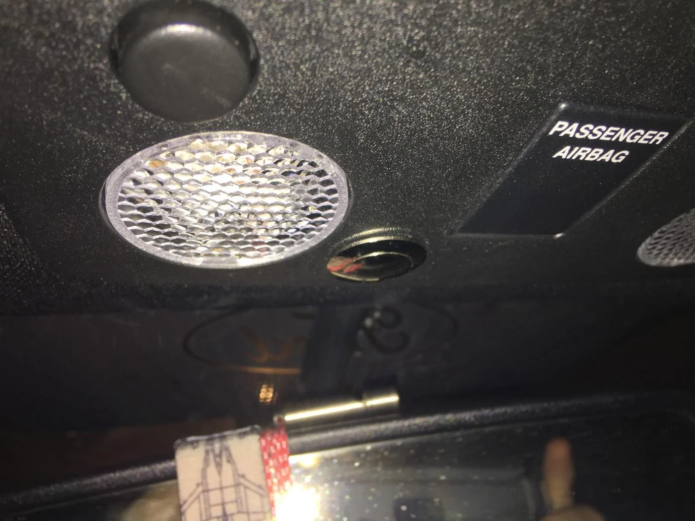
Switch installed in the housing:

Switch and circuit board married into the map light housing:
Final product:
I found a similar write up on another site, but nothing here. I came to the S550 platform from a 2015 Subaru WRX with the premium package. I bought the base GT package. Something that I quickly noticed was that I no longer had a means to open the garage door via homelink. I still have an old fugly garage door opener which I did not want to hang on the visor.
One of my best friends recommended using the internals from the garage door opener to make into a "homelink". With that we went to the electronics store for supplies.
We purchased a simple intermittent switch which would be installed in the car and some thin gauge wiring.
Once we got home we found the best location for the switch install in the map light housing. The reason I picked the map light housing was that the switch would blend in nicely with the map light buttons and the housing itself was easy to remove.
I drilled a single hole matching the switch diameter and installed the switch. My best friend soldered wiring to the circuit board of the garage door opener and then onto the switch itself. I had no idea how simple/complicated this would be to solder to the correct portion of the circuit board. My friend explained that all one needed to do to figure where to solder was to look at the bottom of the original garage door button to figure out where it engaged the garage door circuit board when depressed. Generally it will make two points of contact with the circuit board. Those two points are where you will solder the new wiring.
To ensure that the exposed wiring will not be accidentally effected once installed, my friend used drops of Plastidip to cover any exposed wiring on the board. The plasitdip was applied with a q-tip.
Once the wiring was soldered to the button we tested the system with success. If ever needed, I could remove the circuit board from the map light housing and re-install it into the factory garage door opener housing. The only permanent modification would be the hole in the map light housing. Personally, I would just leave the switch in the hole.
The circuit board was wrapped in electrical tape just to prevent any electrical contact due to any vibration while in the housing. There is quite a bit of factory wiring in that map light housing for the two lights and microphone. We felt pretty positive that it would be easy to install two switches and garage door circuit boards if needed. The circuit board fit perfectly in the empty space in the head liner above the housing.
Here are some pics taken during the install:
Switch installed in the housing:


Switch and circuit board married into the map light housing:

Final product:

Sponsored