Sponsored

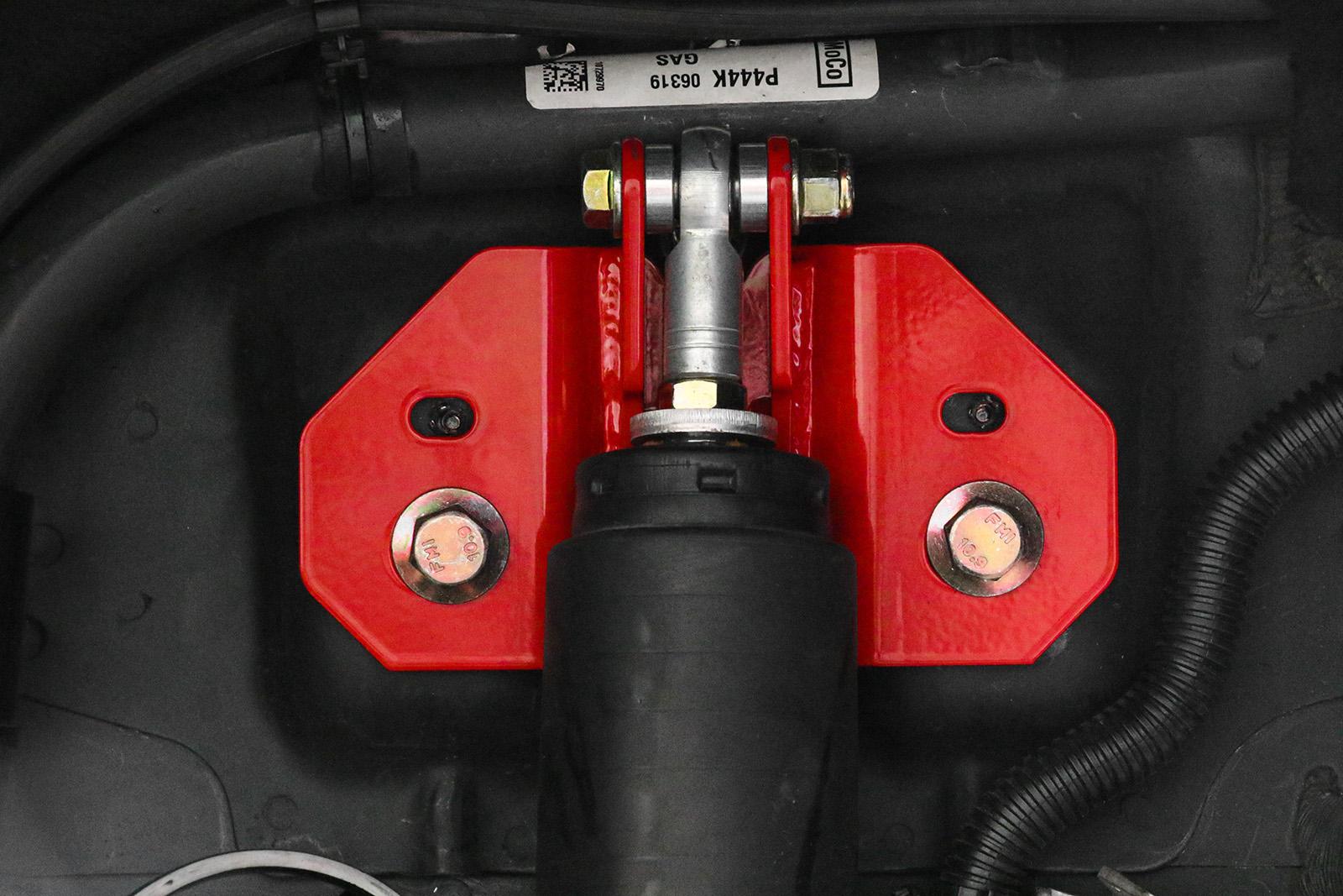
BMR Suspension's New S550 Rear Upper SHOCK MOUNTS: SM760 - Design Finalized!

Status
Not open for further replies.

DivineStrike

Doomsday
Joined
Jan 30, 2014
Threads
82
Messages
2,966
Reaction score
200
Location
Charleston
Vehicle(s)
15 GTPP, 11 F150 FX4, 07 CBR600RR
Would use of another material mimic a spherical bearing solid mount but add in a similar but more communicable failure point? Like derlin etc? Not necessarily as a replacement to the bearing itself. Maybe something within the unit that could be replaced
Sponsored

 

Red65

Well-Known Member
Joined
May 2, 2018
Threads
24
Messages
327
Reaction score
172
Location
MS
Vehicle(s)
Red 1965 Coupe, 2017 Premium MT GT
I understand well that competitors will trade blows now and again because they are actively competing in a volatile market. My issue with Steeda's comment is they put a blanket smear-statement over BMR's product due to literally 1 customer that has had this fender well issue (the 2nd car mentioned had airbags so the mount cant be directly blamed) and it's just poor taste in my opinion. I've seen Steeda do this a lot and according to others in this thread, I am not the only one. If BMR has also gone into Steeda's posts where they are advertising a new product and tried to smear them due to issues customer(s) were having, then shame on them too. It's a two way street.

I do get what you're saying about the stock design failing by design and the reason's why you shouldn't change it, which is perfectly reasonable if you don't lower your car. However, solving the shock travel issue is the primary objective of this product and if it creates other problems (which is what usually happens), then they will tweak the design until they get it right. That's how R&D works. All I'm saying is if there truly is a design issue with a BMR product, they will resolve this with the customer (as they always have; BMR customer service is great) and tweak the design until the issue is resolved. And while neither company should shy away from being competitive against each other, smear statements are distasteful and as seen in the previous page, the customers don't like it.
 

aleccolin

Well-Known Member
Joined
Jun 7, 2017
Threads
30
Messages
745
Reaction score
256
Location
VA
Website
www.CarClubVT.com
First Name
Colin
Vehicle(s)
2016 GT PP
Relative to the OE design, the BMR design is going to create a sort of fulcrum effect and induce a moment resulting in more tension in the mounting bolts, basically prying the weld nuts out of the body which seems to be what happened in the case above. That said, unless the shock is bottoming out or just riding on the bump stops, the only force transmission is by the shock itself, which is there just for dampening after all. Ridetech's coilover mounts add mounting points via rivnuts and if that works, there's nothing saying you can't do the same with these with a slightly revised design. All it has to do is counteract the moment on the mount.

I've had a set of these on the shelf for a couple months, and planned on putting them in this weekend which is why I looked up this thread. I still plan on putting them in, but will definitely pay attention to jounce bumper length or anything else that could cause an issue. I'm using FRPP track shocks, I wonder how the length of the shock body compares to the Vikings?
 

aleccolin

Well-Known Member
Joined
Jun 7, 2017
Threads
30
Messages
745
Reaction score
256
Location
VA
Website
www.CarClubVT.com
First Name
Colin
Vehicle(s)
2016 GT PP
Regarding the Viking Crusader shocks, from what I'm seeing they're designed for very high rebound dampening, which would make more sense with what @S550Whipple15 is saying about the weld nuts being pried out in a downward direction. With very high rebound dampening in the shock, the spring force is being transmitted into those two weld nuts while the suspension is extending, pulling down at the pivot point of the shock mount. Not normally a problem, but these mounts increase the leverage relative to the OE design. Yank on that thing a couple hundred thousand times while driving around and, well there you go.

Are the smaller alignment studs useable at all? They appear to be threaded, but it may be a non-standard thread. I have no idea how they're attached to the sheet metal, it might be a better idea to just drill them out and put in a couple nutserts.
 

BmacIL

Enginerd
Joined
Sep 21, 2014
Threads
69
Messages
15,010
Reaction score
8,921
Location
Naperville, IL
Vehicle(s)
2015 Guard GT Base, M/T
Vehicle Showcase
1
Regarding the Viking Crusader shocks, from what I'm seeing they're designed for very high rebound dampening, which would make more sense with what @S550Whipple15 is saying about the weld nuts being pried out in a downward direction. With very high rebound dampening in the shock, the spring force is being transmitted into those two weld nuts while the suspension is extending, pulling down at the pivot point of the shock mount. Not normally a problem, but these mounts increase the leverage relative to the OE design. Yank on that thing a couple hundred thousand times while driving around and, well there you go.

Are the smaller alignment studs useable at all? They appear to be threaded, but it may be a non-standard thread. I have no idea how they're attached to the sheet metal, it might be a better idea to just drill them out and put in a couple nutserts.
The shock is, for all intents and purposes, vertical, relative to the body when at ride height. The bending moment on the nuts is not significantly different to the stock mount. I'll repeat: shock/abuse loads (pot holes) will cause crack initiation here. Without a sacrificial failure point, this can happen with said loading. Accept it and install the part or move on and keep the less-than-excellent ride & performance of the stock mount.
 

Sponsored

aleccolin

Well-Known Member
Joined
Jun 7, 2017
Threads
30
Messages
745
Reaction score
256
Location
VA
Website
www.CarClubVT.com
First Name
Colin
Vehicle(s)
2016 GT PP
The shock is, for all intents and purposes, vertical, relative to the body when at ride height. The bending moment on the nuts is not significantly different to the stock mount. I'll repeat: shock/abuse loads (pot holes) will cause crack initiation here. Without a sacrificial failure point, this can happen with said loading. Accept it and install the part or move on and keep the less-than-excellent ride & performance of the stock mount.
I disagree, there is a difference, and it's significant. I'm not going to bust out my statics texbook and start drawing FBDs here, but there is an obvious difference in where the force is acting on the mount relative to the OE design which is pretty much right between the mounting bolts, just a little bit above CL. If the system was actually vertical, perfectly rigid, and the bolts acted in pure shear it wouldn't much of an issue, but the mounting face is at a slight angle, maybe 10 degrees off vertical, and there's probably a lot more movement even in stock form than we realize - it's just sheet metal after all. The BMR design moves the force acting on the mount upward close to 3" and slightly further outboard, taking what is probably a 1/2" lever arm from the OE mount and changing that to a roughly 3 1/2" lever arm. That could easily increase the reactions at the mounting bolts, and under the right conditions cause a failure.

I think it's disingenuous to simply say "accept it and move on" or disregard this failure as a pure fluke when it may preventable. What I'm seeing in those pictures is fatigue cracking, and that begs further investigation. I'm not bashing BMR here, I like and use their products and I'm using these mounts, but I'm interested in figuring out a way to mitigate the risks.


BmacIL

Enginerd
Joined
Sep 21, 2014
Threads
69
Messages
15,010
Reaction score
8,921
Location
Naperville, IL
Vehicle(s)
2015 Guard GT Base, M/T
Vehicle Showcase
1
I disagree, there is a difference, and it's significant. I'm not going to bust out my statics texbook and start drawing FBDs here, but there is an obvious difference in where the force is acting on the mount relative to the OE design which is pretty much right between the mounting bolts, just a little bit above CL. If the system was actually vertical, perfectly rigid, and the bolts acted in pure shear it wouldn't much of an issue, but the mounting face is at a slight angle, maybe 10 degrees off vertical, and there's probably a lot more movement even in stock form than we realize - it's just sheet metal after all. The BMR design moves the force acting on the mount upward close to 3" and slightly further outboard, taking what is probably a 1/2" lever arm from the OE mount and changing that to a roughly 3 1/2" lever arm. That could easily increase the reactions at the mounting bolts, and under the right conditions cause a failure.

I think it's disingenuous to simply say "accept it and move on" or disregard this failure as a pure fluke when it may preventable. What I'm seeing in those pictures is fatigue cracking, and that begs further investigation. I'm not bashing BMR here, I like and use their products and I'm using these mounts, but I'm interested in figuring out a way to mitigate the risks.


I'd encourage you to take the measurements and do the FBD. Go to the next step and factor in contact area for the load to be distributed to assess stress. No, they're not in pure shear but also not nearly the bending load you're thinking. Installed like that (as at least one of the two failure cases was, sans bumpstops), it's a recipe for failure for a street driven car. I have 10k street miles, over 10 autocross events and a handful of track events with them and there are no issues. Maybe it's the higher rate rear springs, and/or the combination of FP track shock damping rates and trimmed stops, but I cannot say I've been too kind and they've seen plenty a rough road and bumps.
 

aleccolin

Well-Known Member
Joined
Jun 7, 2017
Threads
30
Messages
745
Reaction score
256
Location
VA
Website
www.CarClubVT.com
First Name
Colin
Vehicle(s)
2016 GT PP
Cool, that might be an easy place to drill out and install some beefy nutserts then, another attachment point can't hurt.
 

aleccolin

Well-Known Member
Joined
Jun 7, 2017
Threads
30
Messages
745
Reaction score
256
Location
VA
Website
www.CarClubVT.com
First Name
Colin
Vehicle(s)
2016 GT PP
I'd encourage you to take the measurements and do the FBD. Go to the next step and factor in contact area for the load to be distributed to assess stress. No, they're not in pure shear but also not nearly the bending load you're thinking. Installed like that (as at least one of the two failure cases was, sans bumpstops), it's a recipe for failure for a street driven car. I have 10k street miles, over 10 autocross events and a handful of track events with them and there are no issues. Maybe it's the higher rate rear springs, and/or the combination of FP track shock damping rates and trimmed stops, but I cannot say I've been too kind and they've seen plenty a rough road and bumps.
Very glad to hear you haven't had an issue, I'm only on the FRPP track shocks which shouldn't be as aggressive as the Vikings, and I doubt I'll go to anything more aggressive in the future. I'm on Steeda adjustable rear springs, they're a pretty high springrate and set fairly low, so I'm thinking about taking the boot off the shock and running just the bump stop and mounting a GoPro somehow to see if that shows anything, excessive bump or anything flexing.

If anyone is interested I ordered some dust seals from SRI down in Mooresville, the washer thickness is around 50 thou so I'll probably turn a little off the spacers to fit. Also ordered some 70mm through bolts so the grip will extend all the way through. Mine was an early set so it has the low profile jam nuts (which are wonky as hell, btw) and the large bump washer, so I also ordered some nuts that are around 8mm tall and I'm thinking about turning the OD of the washers down a bit.

Did someone say those bump washers were aluminum? Mine are heavy, non-magnetic, look like SS.

https://sealsit.com/product/rod-end-seal/

http://www.sriperformance.com/rod-end-seals-p/sit-ws10mm.htm


SIT-WS1000-2.jpg

Rod-end-drawing.png


Rod-end-chart-image-e1475338506804.png
 

BmacIL

Enginerd
Joined
Sep 21, 2014
Threads
69
Messages
15,010
Reaction score
8,921
Location
Naperville, IL
Vehicle(s)
2015 Guard GT Base, M/T
Vehicle Showcase
1

BmacIL

Enginerd
Joined
Sep 21, 2014
Threads
69
Messages
15,010
Reaction score
8,921
Location
Naperville, IL
Vehicle(s)
2015 Guard GT Base, M/T
Vehicle Showcase
1
Cool, that might be an easy place to drill out and install some beefy nutserts then, another attachment point can't hurt.
Most certainly not. A riv-nut there would probably add some robustness for sure.
Sponsored

 
Status
Not open for further replies.


Top