roadracergt
Active Member
- Thread starter
- #1
Hello My Mustang 6G Friends:
I finally had a chance to do my technical review of the BMR chassis brace (CB006). This is my own analysis & I welcome other suspension/chassis engineers to offer their feedback and/or analysis as a point of comparison. I ask that you read the full analysis & understand the level of testing I have performed & offered up as an explanation to help you with your future upgrades.

A torsional load (T1) is exerted on the chassis by a roll moment during cornering, which causes the chassis to flex. This load is transmitted to the mounting locations of the chassis brace (intended to reduce the chassis flex) and can be evaluated as forces at each mounting point. The force (F1) applied to point A causes unnecessary shear and bending stresses at the weld between the bracket and the tubing because the point does not lay in-line with the horizontal axis (x-axis) of the brace.
These stresses could lead to the bracket permanently deforming, or worse, causing a fracture in the weld, ultimately leading to the two pieces breaking apart. The secondary mounting point B is improperly located due to the added force (F2) that is being applied to the factory lower control arm bolt utilized in this kit. The force induces a shear stress on the factory control arm bolt, which is compounded by the oversized hole (shown in Figures 2 and 3) that reduces structural integrity by not leaving enough contact surface area for the flange of the bolt to adequately seat against and does not locate the brace properly.


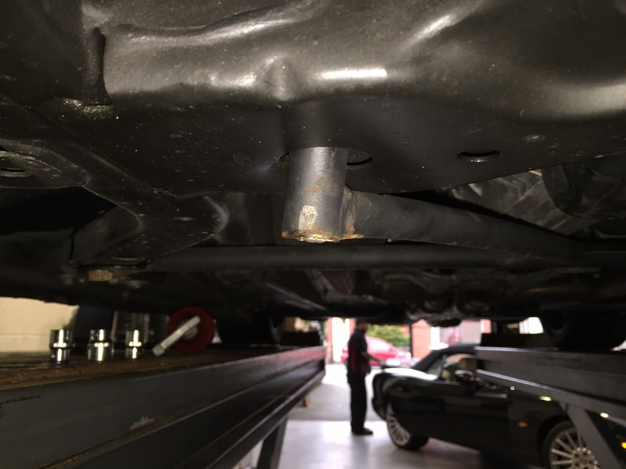
This in turn, leads to another problem: the brace not adequately mounting at point B. By not locating and securing the brace, this gives it the ability to shift, negating its intended purpose of reducing chassis flex. The evidence of this movement can be seen below (Figures 4 and 5).

To summarize my findings & research, this chassis brace was designed without considering some key design and structural elements.
Why would you add additional stresses (e.g., the forces being applied by the flexing of the chassis) to such a critical suspension component on the vehicle like the lower control arm bolt?
That fact, along with other issues brought up previously, show that this chassis brace does not meet its intended purpose of reducing chassis flex as much as you would think.
In closing, the most effective product for your money would be the 2-point chassis brace that has the mounting locations in-line with the horizontal axis of the brace.
Time to enjoy the weekend!
I finally had a chance to do my technical review of the BMR chassis brace (CB006). This is my own analysis & I welcome other suspension/chassis engineers to offer their feedback and/or analysis as a point of comparison. I ask that you read the full analysis & understand the level of testing I have performed & offered up as an explanation to help you with your future upgrades.

A torsional load (T1) is exerted on the chassis by a roll moment during cornering, which causes the chassis to flex. This load is transmitted to the mounting locations of the chassis brace (intended to reduce the chassis flex) and can be evaluated as forces at each mounting point. The force (F1) applied to point A causes unnecessary shear and bending stresses at the weld between the bracket and the tubing because the point does not lay in-line with the horizontal axis (x-axis) of the brace.
These stresses could lead to the bracket permanently deforming, or worse, causing a fracture in the weld, ultimately leading to the two pieces breaking apart. The secondary mounting point B is improperly located due to the added force (F2) that is being applied to the factory lower control arm bolt utilized in this kit. The force induces a shear stress on the factory control arm bolt, which is compounded by the oversized hole (shown in Figures 2 and 3) that reduces structural integrity by not leaving enough contact surface area for the flange of the bolt to adequately seat against and does not locate the brace properly.
This in turn, leads to another problem: the brace not adequately mounting at point B. By not locating and securing the brace, this gives it the ability to shift, negating its intended purpose of reducing chassis flex. The evidence of this movement can be seen below (Figures 4 and 5).

To summarize my findings & research, this chassis brace was designed without considering some key design and structural elements.
Why would you add additional stresses (e.g., the forces being applied by the flexing of the chassis) to such a critical suspension component on the vehicle like the lower control arm bolt?
That fact, along with other issues brought up previously, show that this chassis brace does not meet its intended purpose of reducing chassis flex as much as you would think.
In closing, the most effective product for your money would be the 2-point chassis brace that has the mounting locations in-line with the horizontal axis of the brace.
Time to enjoy the weekend!
Sponsored