Sponsored

Rear Speaker Deck Removal and Amp Install

OP
OP

Heinoceros

Well-Known Member
Joined
Nov 23, 2014
Threads
3
Messages
83
Reaction score
43
Location
houston
Vehicle(s)
Yellow 2015 GT
looked like it was going to rain for another 39 days, so ive still got some time to build that ark. For now i cleaned out the garage to do this under cover.

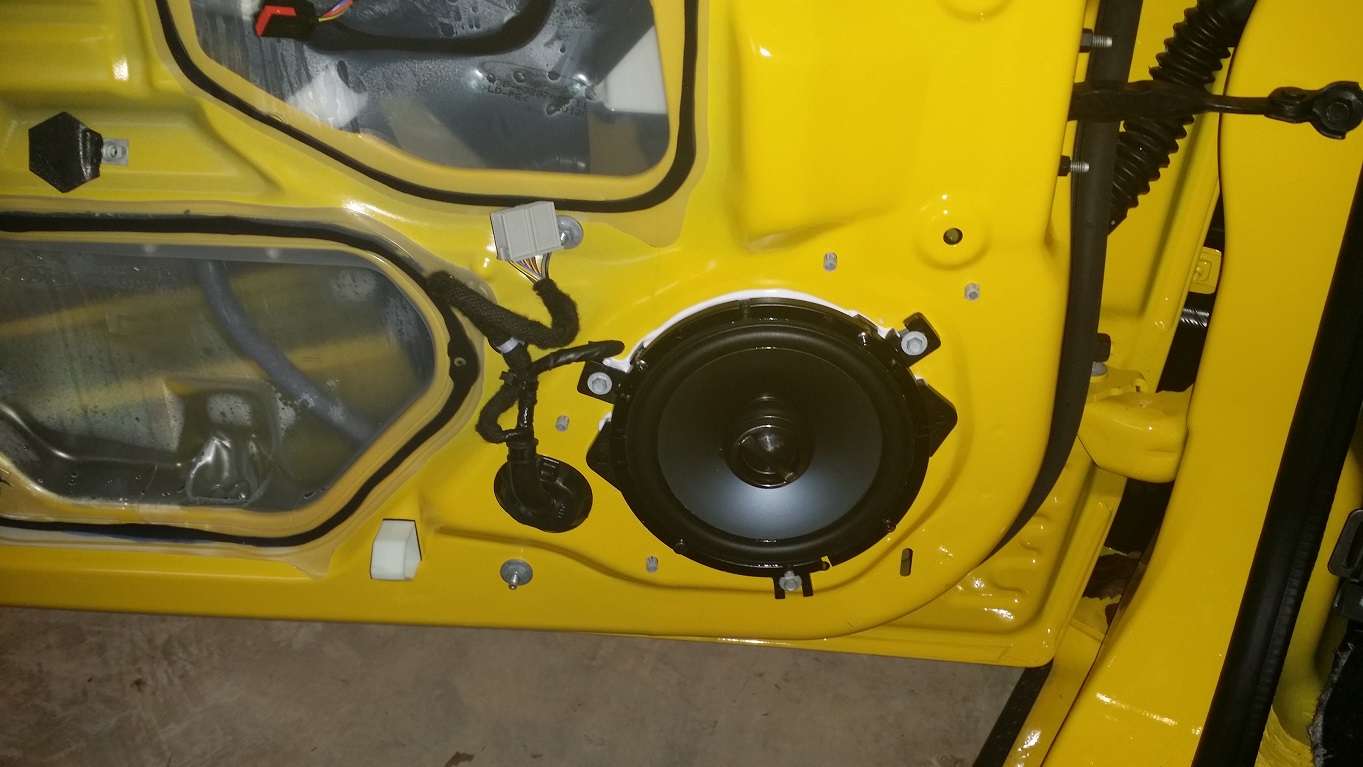
so i have removed the door panel. As always, it was a little harder than i expected. The steps are as follows, all except the last couple are documented above in more detail.

1) remove pesky bolt covers under latch with hook scribe. (see above)

2) pry off window/lock switch panel. Use non-metal pry bar, this thing scratches easy. Unclip wiring harness to switch. (see above)

3) remove the two uncovered 10mm bolts (see above)

4) remove the two 7mm bolts along the bottom of the door panel.

5) the only thing left holding in door panel are clips. It seemed very resistant to pulling and prying from the sides. But when i pulled up and out (towards the car interior) at the bottom of the panel, it came free relatively easily.

6) there were three separate wiring harnesses with my car, but its the base model. You might have more. They detach easily.

7) remove the latch cable. The cable itself is pretty standard, you maneuver the little short cylindrical end bit out of the latch, and then you squeeze the end of the cable housing, and pull it out of the bracket it is in. I have included a picture which shows where to do this on a cable that has been removed.

Thats it! so simple!


Sponsored

 
OP
OP

Heinoceros

Well-Known Member
Joined
Nov 23, 2014
Threads
3
Messages
83
Reaction score
43
Location
houston
Vehicle(s)
Yellow 2015 GT
speakers installed. Used the pre-existing wires because the door loom looked like a real bitch to add wires too. The pre-existing wires are nice and stout, so it shouldnt be a problem.

I caulked in the alpine bracket, it fits pretty good, although i would have been happier if the stock bolts holes didnt stick out a bit from the door. The caulk should seal it up, but if it vibrates or rattles, i will be back in here.

The wires go into the door from a connector right under the driver side kick panel. It comes off pretty easily. You need to pull off the sill panel first, it just pulls straight off. Then you need to remove the hood opening lever. There is a little black bolt cover on what looks like a 10mm bolt head. However, this bolt head isnt a bolt, its a clip that has little tabs on it that keep you from pulling off the lever. You need to push a 10mm 1/4inch drive socket onto it very hard to retract the clips, and while doing this, pry off the lever. Its kind of tricky.

after thats off, just pull the kick panel off towards the rear of the car. Do not pull it straight out, pull it backwards toward the rear tire. I broke off a tab trying to pull it straight out (towards the other door). Its the least important tab, but i will still have to epoxy it back on.

on the base model, the wires are the white and white/brown stripe wire at the end of the connector. I think the 401 cars have different colored wires here (and the amp is right under this panel too) but they are supposed to be at the same spot in this connector.

[EDIT] - i have spent some time looking at this, and if you have the shaker upgraded audio, you will not want to wire it like this. You will want to intercept the speaker inputs or outputs at the Amp, which should be right behind this driver side kick panel. I have included a snippet of the wiring diagram for the Amp going out, so you should be able to do all of your speakers in one spot using those color codes. the picture is later in this thread, so keep reading. Although if you have the upgraded shaker system, you probably want to use the lines coming into the amp anyway, and avoid the whole high to low conversion for input signals. I will try and find a snippet from the wiring diagram that shows the input for the shaker system.

[EDIT] - found the diagram, its later in the thread.


Last edited:

draco24433

Well-Known Member
Joined
May 23, 2014
Threads
23
Messages
1,355
Reaction score
228
Location
Kissimmee, FL
First Name
Alex
Vehicle(s)
2015 Oxford White Mustang GT Premium
Keep up the great job and thanks for all the details. I wanted to ask you what the connector next to the speaker is for. Was it for the old speaker?
 
OP
OP

Heinoceros

Well-Known Member
Joined
Nov 23, 2014
Threads
3
Messages
83
Reaction score
43
Location
houston
Vehicle(s)
Yellow 2015 GT
Keep up the great job and thanks for all the details. I wanted to ask you what the connector next to the speaker is for. Was it for the old speaker?
that connector is a big many pronged thing that attaches to the buttons on the armrest. for the windows and locks and mirrors.

I reused the speaker connection. I clipped off the connector. I might have been able to cut away the other end of the connector which was attached to the stock speaker, but it would have required a lot of surgery. So i just clipped the wires and wired up the new speaker to them.
 

draco24433

Well-Known Member
Joined
May 23, 2014
Threads
23
Messages
1,355
Reaction score
228
Location
Kissimmee, FL
First Name
Alex
Vehicle(s)
2015 Oxford White Mustang GT Premium
Great. Thanks!
 

Sponsored

Laztug

Wanna run dyno slips bro?
Joined
Aug 12, 2014
Threads
24
Messages
1,115
Reaction score
287
Location
COTUS
Vehicle(s)
Calling out OKC #1 spot after axle back install.
Great write up!
 

CMC#5

Well-Known Member
Joined
Sep 28, 2014
Threads
8
Messages
47
Reaction score
9
Location
Texas
Vehicle(s)
07 GT
Heinoceros, thanks for documenting this in such detail, it'll be a great resource.

You installed the line converter for the rears out back right next to the amp I'm assuming. What did you do for the fronts though? It looks like since you have the OE wiring from the radio to the door speakers split at the kick panel you'd have connected to the radio side and run wires to the amp out back and then right back to the same spot to connect to the door side. Correct?
 
OP
OP

Heinoceros

Well-Known Member
Joined
Nov 23, 2014
Threads
3
Messages
83
Reaction score
43
Location
houston
Vehicle(s)
Yellow 2015 GT
Heinoceros, thanks for documenting this in such detail, it'll be a great resource.

You installed the line converter for the rears out back right next to the amp I'm assuming. What did you do for the fronts though? It looks like since you have the OE wiring from the radio to the door speakers split at the kick panel you'd have connected to the radio side and run wires to the amp out back and then right back to the same spot to connect to the door side. Correct?
The AudioControl line converter i am using only takes in one set of inputs, so i am just using the stock rear speaker output for the amp inputs, and controlling the front/rear balance with the amp. You are right, i could easily route those original front speaker outputs through a second converter back to the amp as well, since i am already cutting into the front speaker wires.

Basically i would be paying 80 bucks (for the second line converter) to get the ability to control the fade from the head unit. And i may do this at some future point, but historically in my cars once i figure out the balance front/rear, i dont ever change it again, so it doesnt seem that important to me.

there is one slightly non-trivial problem doing this. The passenger side speaker wires actually have a Y at the connector, with one set of wires going to the radio, and the other set going to the tweeter. The wires are identical, and share the same hole on the connector. So you might have to cut both of them to find which one is coming from the radio. (It seems like the y should have been coming from the radio, and then y-ing out to the tweeter and door speaker, but it wasnt.)

EDIT - sorry i am being an idiot, you could just use the stub end left over after you cut in to attach the amp output to the speaker. no reason to mess with the 2 wires coming into the connector. I will add a picture of the passenger side kick panel tonight or tomorrow.
 

CMC#5

Well-Known Member
Joined
Sep 28, 2014
Threads
8
Messages
47
Reaction score
9
Location
Texas
Vehicle(s)
07 GT
The kicker has a tweeter in the A pillar plus the two speakers in the door. So do you mean on the radio side of the connector there is an extra pair of wires that go up to the a-pillar or that on the door side of the connector there are four wires, two which go to the 6.5 driver and two that go to the other speaker higher up in the door?
 

Sponsored
OP
OP

Heinoceros

Well-Known Member
Joined
Nov 23, 2014
Threads
3
Messages
83
Reaction score
43
Location
houston
Vehicle(s)
Yellow 2015 GT
The kicker has a tweeter in the A pillar plus the two speakers in the door. So do you mean on the radio side of the connector there is an extra pair of wires that go up to the a-pillar or that on the door side of the connector there are four wires, two which go to the 6.5 driver and two that go to the other speaker higher up in the door?
i have the base model, so i only have one speaker in the door. on my system, there is an extra pair of wires that go up to the a-pillar that are joined with the wires coming out.

here are some pics. It looks like the shaker system uses the same colors for the 6.5 inch speaker in the door, but instead of just wiring that same circuit through the tweeter in the a-pillar, it adds a new circuit (violet-grey and yellow-grey on the right hand side, green-blue and grey-blue on the left hand side). It doesnt go through the C213 connector that i am using, it appears to be solid all the way from the amp output to the connector at the door. That is terrible. Getting into the connector at the door is just impossible looking to me. So you would want to intercept it at the Amp. The amp is super accessible, so this should actually make the whole job easier. But if you try to do it via the C213 connector, you will only be working with the door tweeter, and i think that will have gone through a crossover, so you dont want to use that.

and of course if you have the upgraded shaker system, you have an amp already and can use the amp inputs directly instead of doing this whole high/low conversion stuff. i added a picture of
the amp wiring if you want to tap into the amp inputs.


Also, if you look closely at the wiring diagram, there is a typo in it. It says LF SPKR on the violet-grey and yellow-grey wires when it clearly should say RF SPKR.

that C213 connector is the one in the picture, so its easy to get.


snippet of the wiring diagram for the base model.


snippet of the wiring diagram for the shaker system.


snippet of the wiring diagram for the amp


(note, i am including snippets of wiring diagrams under the Fair Use for Research/Teaching, since this is clearly research and teaching going on here.)
 
Last edited:

CMC#5

Well-Known Member
Joined
Sep 28, 2014
Threads
8
Messages
47
Reaction score
9
Location
Texas
Vehicle(s)
07 GT
Ah ok. I didnt realize the base system had a tweeter in the a pillar. I figured only the shaker did. Actually, there are three systems, the base base, the premium (MFT) and the shaker (401a) so which do you have and which is the "base" depicted above? Where are you getting those wiring diagrams, those are very helpful!

I hadnt even considered the active noise cancellation stuff. Is that for all models?
 
OP
OP

Heinoceros

Well-Known Member
Joined
Nov 23, 2014
Threads
3
Messages
83
Reaction score
43
Location
houston
Vehicle(s)
Yellow 2015 GT
Ah ok. I didnt realize the base system had a tweeter in the a pillar. I figured only the shaker did. Actually, there are three systems, the base base, the premium (MFT) and the shaker (401a) so which do you have and which is the "base" depicted above? Where are you getting those wiring diagrams, those are very helpful!

I hadnt even considered the active noise cancellation stuff. Is that for all models?
the wiring diagrams dont distinguish between the 9 speaker and 12 speaker options. it may be that the 12 just includes the subwoofer and two extra speakers that still run off of the 8.1 amp, but i dont know that for sure.

the base system i have is the absolute cheapest one, the 6 speaker no amp version of the car. It looks like even the base model has 3 mics for noise cancellation, which is a little surprising. The bluetooth phone even in the base model is pretty decent.

i am getting the wiring diagrams through the ford motorcraft service subscription. It gives you access to all kinds of nice stuff, although the service documents for things like panel removal are not great. The wiring diagrams are fantastic though, its worth it just for those.

it was 20 bucks for one month of access.
http://www.motorcraftservice.com/vdirs/retail/default.asp?pageid=&gutsid=
 
Last edited:

CMC#5

Well-Known Member
Joined
Sep 28, 2014
Threads
8
Messages
47
Reaction score
9
Location
Texas
Vehicle(s)
07 GT
Interesting and disappointing that the wiring diagrams dont distinguish between the 9 and 12 speaker setup. I hunted around Fordparts.com using vin numbers from a 400 and 401a cars and there are definitely different component diagrams for those two sound systems. The part numbers for the components that exist in both are the same but the prices are not the same! For example the rears in the 401A are $56 and in the 400 they're $28. Neither list a price for the audio chassis so tough to see if those are the same or not. In both cases the amp was listed as the same price $258. My suspicion now is that the sub in the 401 takes the signal from the rear speakers at the back and the enclosure has its own bypass and amp. This also would jive with the fact that both stereos have the same bass/treble control and fade control. In other words the 401a doesnt have some incremental base boost control.

Sorry if I've highjacked your thread a bit! :)
 

TheColorRed

Active Member
Joined
Nov 23, 2014
Threads
0
Messages
28
Reaction score
1
Location
Houston
Vehicle(s)
2015 Race Red v6
Hmmmm...you already got all the panels out...why not just run your own aftermarket speaker wires? Why bother messing with the factory wiring and looking up wiring diagrams?
Sponsored


Top